SJSoane
-
Posts
1,655 -
Joined
-
Last visited
Content Type
Profiles
Forums
Gallery
Events
Everything posted by SJSoane
-
 Hi Alexandru, Beautiful craftsmanship. A joy to look at. I just noticed the red inboard planking, coming right down to the deck. Did you paint/stain each piece before installing, or did you install, mask and then paint? Best wishes, Mark
 -
Hi Gary, Looks great. It does make you think about how a relatively few cooks with only a relatively few cooking surfaces and pots could cook for 650 men even if it was in shifts. Think about a kitchen today for a typical banquet hall, in comparison. Best wishes, Mark
-
Hi Remco, Perfection. It is really interesting to see this earlier brick style stove. With my architecture background, it seems so incongruous to build bricks on top of a wooden frame, rather than a solid foundation in the ground. Would any engineers out there be able to calculate the weight of this relative to an iron stove? Best wishes, Mark
-
Hi Mark, I would agree with Gaetan about considering building version 2 in the Antscherl method, rather than the Hahn method. I used a modified Hahn method on my Bellona before I even knew about Antscherl's method, and if I had it to do over again I would without hesitation build it right side up. Much easier to see what is really going on and adjust, and it is more fun to work on a ship as it would really look, right from the beginning. I spent years looking at an upside down hull, wondering what it would look like when I could finally turn it over. Why delay the gratification? But whatever you are most comfortable with. Best wishes, Mark
-
Hi Michael, I was just able to catch up on your log. It is a joy to reach how you approach each problem, and then come up with close to perfect tooling and workmanship. Lessons for us all. Best wishes, Mark
-
Hi Ed, I only rarely get a chance to look in lately, and your project is coming along nicely! Best wishes, Mark
- 3,618 replies
-
- 1
-

-
- young america
- clipper
- (and 1 more)
-
Gaetan, A perfect setting for a museum quality project. Mark
-
HI everyone, This is indeed a fascinating issue; the more you look at it, the more interesting it becomes. Thank you Gaetan, for showing us the French method. I know very little about the French traditions--except that my Bellona was apparently copied from a captured successful French ship--and it is very interesting to see the constructional differences. As I begin building the stern, I am astounded at the constructional complexity and subtle visual effects they worked so hard to achieve. Beauty still counted for a lot back then! Best wishes, Mark
-
Hi Gary, The photo I was thinking of is on page 27 of the AOS for the Bellona, HMS Ajax of 1767. You can see the two kick in place pawls on the fore side of the capstan partners. I have seen your cross section photo in a book, but I can't remember where. I'll look around. Le me know what else you find out! Best wishes, Mark
-
Looks great, Remco. Did you silver solder the pot?
-
Hi Gary, Here are some photos of the capstan in the ca. 1760 Bellona model, at midships. It shows the simple "kick under the capstan" kind of pawl. In my Bellona Admiralty drawings, the capstan shown here on the upper deck has a space as shown here for the pawl to go underneath, presumably to a rachet of some kind? But the capstan directly underneath on the gundeck does not show a similar space between it and the deck. Does this suggest that the gundeck capstan had no pawls? There is some evidence that this model was built while the ship was under construction in 1760 (relocations of the gunports are drawn in over the original drawing with instructions to the dockyard; these correspond to the locations of the gunports in the model.) However, there are some details like gratings of very different sizes, which suggest some things were repaired, or replaced over time. Whether the capstan is original I cannot say! I would guess that while the capstan might have been replaced later, less likely they would have pulled up the capstan partners in a repair... And then there is the photo of the split hull model of a gundeck shown in the AOS of the Bellona--the Ajax?--which shows two kick under pawls located closer together. So I am guessing this is the norm through the 1760s-70s at least. Best wishes, mark


-
Ed, it is looking very nice indeed. I learn from every post you make. Mark
-
Remco, Nice, very nice! Absolutely convincing. Mark
-
Thanks, everyone, I am working on wood now thanks to all of your help. And Alex, thank you very much for the Ardent drawing. That is the only drawing except Steel's 80 gun ship that I have seen of the old fashioned stern with the balcony like the Bellona. It helped me enormously to check the various curves against my own reconstruction. Best wishes, Mark
-
Gary, So how did you get the cast iron look? Mark
-
Gary, Looks absolutely spectacular! Mark
-
Hi everyone, So I think I see how this works, now that I have looked at the quarterdeck plan more closely, I believe there is enough space between the aftermost beam and the transom to allow the decking to smoothly rise from the normal beam roundup to the higher roundup on the transom. All beams keep the same roundup, the transom matches the roundup of the lights, the deck connects the two. You can see how this would work in the photo of the model. The quarterdeck planks at midship can be seen through the doorways in the side, sitting on top of the transom. So you were all right about the standard beam roundup, and I was right about a higher roundup on the transom. Re-reading the obscure parts of Steel sometimes reveal unexpected insights! Ahhh..... Mark

-
Sorry, forgot to add in response to Ed's last post. I now think this is probably right, that the last five beams are slightly adjusted to pick up the 2 inch difference by the time the deck hits the transom. This is now my story and i am sticking with it...;-) Mark
-
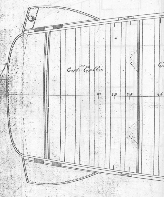
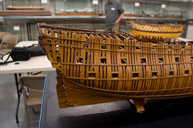
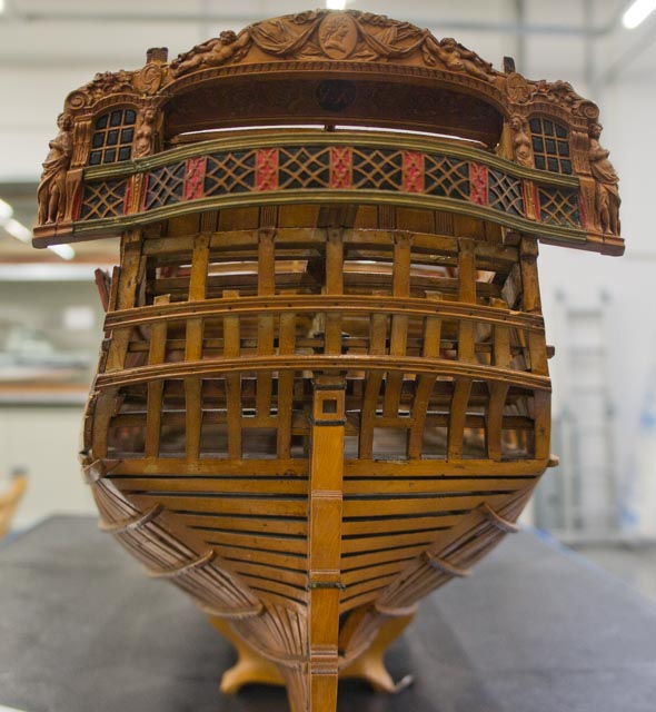
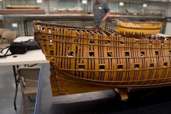
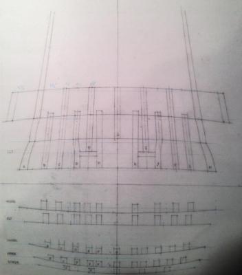
Hi everyone, I deeply appreciate your help on this increasingly interesting question. As you have all seen, I am trying to deduce the roundup at the stern transoms from the sheer diagram which shows the beam heights at the side and midships; I can also measure the heights of the knuckles of the upper and lower counters from the sheer diagram since it shows the stern timbers at the sides and midships. Now it would be nice to validate this against a drawing of the stern; but very unfortunately, there is no drawing of the Bellona's stern that I have ever been able to find in the Maritime Museum collection. I only have photos of the 1760 model. So I have been reconstructing the stern construction from what I believe I know from the sheer drawing, and what I can infer from the photos of the model. I have attached my working drawing of the stern (ignore the 5 plan drawings of the various transoms and knuckles at the bottom of the drawing). I am showing my reconstruction of four lines: lowest is the roundup of the wing transom; then above it the line of the knuckle at the top of the lower counter; then above it the line of the knuckle at the upper counter which is also the line of the sills of the lights; and then finally the line at the top of the quarterdeck transom which is also the head of the lights. And the best I can tell, as Ed mentioned, the roundup of the knuckle of the lower counter is not the same as the transom of the upper deck behind it. Nor is it the same as the line of the knuckle of the upper counter or the transom of the quarterdeck. But I believe from looking at the model that the quarterdeck decking sits directly on the quarterdeck transom, and so the quarterdeck transom has the same roundup as the quarterdeck beams behind it. I am showing here the roundup of the quarterdeck transom as I measure it in the sheer drawing; 5" at the outer face of the transom at midships. The balcony obviously carries out beyond that. So this is where druxey's warning is important. If I dropped the roundup of the quarterdeck transom to 3" here, I think the stern lights would look squished at the top. I was surprised to see that there are five beams in the quarterdeck abaft the last gunport. So if adjustments have to be made to kick it up at the stern to match the transom, it will be 5 beams to fix. Last thing, Steel says, the "lower gallery lights in the length on the rake should be 3'-6"." That suggests that the upper knuckle and the top of the quarterdeck transom would be parallel. Even at 5" roundup mine looks flatter at the quarterdeck transom. A little worrying. And regarding the quarterdeck transom, Steel says, "round up agreeably to the lights below, and moulded as broad as can be gotten." That seems to affirm Ed's idea that the transom was adjusted to make the stern lights look right. And yet the model shows the deck the same as the transom. My head hurts.... Best wishes, Mark

-
Thanks, druxey, I began to think I was going mad. Tomorrow I'll have to look at how many beams in the stern will have to be adjusted from the standard radius for this to work. It may only be a few, since I assume the deck would want to be at the standard roundup at least past the sternmost gunport. I will keep in mind Ed's good thought that the captain's table will want a smoothly faired deck to sit on so it doesn't rock. I would certainly be annoyed if I were the captain, and there was an abrupt lump in my deck... Best wishes, Mark
-
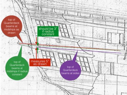
Hi everyone, Thank you for your thoughtful contributions to this interesting question of the beam roundup. I am reconciled to averaging the roundup between midships and at the transom. But just for the record, I have attached an annotated drawing of the situation. The deck would droop if the radius for the beams is held constant. I have also attached my photo of the 1760 Bellona model, showing that the quarterdeck decking clearly sits on top of the transom above the lights, and so the transom does not have a different roundup from the deck. It may be druxey, Greg and Ed have the right idea; the roundup must have increased over the gunroom in the final set of beams in the quarterdeck. But more subtle than I think I want to address in my model.... Best wishes, Mark

-
Thanks, everyone, this is perplexing. I completely understand why the shipyard--and the model shipbuilder--would want constant radii on beams. I did the calculation druxey suggested, and if I kept the radius constant based on the 8 ½" at midships, then the roundup at the stern transom would be a shade over 3"; or 2" short of what I measure in the admiralty sheer plan as the difference between the beam heights at the side and at the center. I was intrigued by Ed's quote from Steel, which says the decks are to have sufficient round abaft, to correspond to the roundup of the stern above the lights; but I could only read this as the curve in plan, not cross section. I think I am reconciled to the possibility that there is a mistake in the Admiralty drawing, or there is something else going on that I cannot resolve. I think that the roundup at the stern is more important to maintain, so the lines of the heads and sills of the stern lights are agreeable with each other. So I think I will split the difference, and use a constant roundup based on 4" at the stern transom which would equate to 9 ½" at midships. That makes a sanding difference, as Ed wisely advises, split between midships and at the stern. Thanks, everyone, onwards and upwards (until someone finds and obscure quote somewhere that would explain this). Best wishes, Mark
-
Toni, very nice. I had to give up on the pump tubes on my build because of my framing system, but before I did so, I came to appreciate just how complicated those are when they come through the deck. Many parts in motion! Best wishes, Mark
-
Hey, Remco, go for it! I can't wait to see this at your usual exceptionally high standard! Are you going to have to lower the beams at the bow to make this fit? Best wishes, Mark
-
Hi everyone, First of all, thanks druxey for helping me past my misunderstanding about geometry. On further investigation the problem still continues, though. I discovered a mistake in measuring width (I was measuring to the inside of the frames), but now corrected to outside the frames I still come up with different radii at midships and at the stern transom. I forgot to mention that I got into this because I was using some large radius template for drafting the beam roundup, and I discovered I needed a different radius for the two locations. So then I looked up some arc calculators online, and calculated the radius at midships as 60" at midships (42'-6" wide, 8 ½" rise converted to 1:64 scale); the radius calculated at the stern (25'-5" wide, 5" rise converted to 1:64 scale), calls for a 36" radius. These correspond to the templates I needed when I physically constructed them. Whichever way I look at it, the radius of the beam roundup at the stern appears to be smaller (giving a higher rise at a given width), than at midships. And I have measured these heights on the sheer drawing showing the top of beam lines at the side and at the center, so I am not getting confused by a transom that is a different radius from the deck beams. I am pretty sure at this point that the radii change, but in this case, they are getting smaller further aft, creating a higher rise. Greg, do you recall where you read about changing radii? I am suddenly very interested, and also soberly thinking about how efficiently I am going to construct beams with unique radii aft of midships.... It would be tempted to fudge this, except that an accurate radius at the stern is essential to the overall effect of the roundups of the windows, counter knuckles, etc. And the stern radius would make the deck at midships look quite rounded. There is always a new problem to solve! Best wishes, Mark