

minimini
-
Posts
56 -
Joined
-
Last visited
Reputation Activity
-

-
 minimini got a reaction from GrandpaPhil in HDMS FREYA 1789 by minimini - scale 1:48 - 40-gun Danish frigate
while waiting for the glue to dry I decided to do the fairing on bulkheads L , M And N the 3 foremost bulkheads before I glue them on
Michael
-
minimini reacted to EdT in Young America 1853 by EdT - FINISHED - extreme clipper
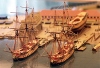
Young America - extreme clipper 1853
Part 210 - Mainstay
Once the main shrouds were installed the main stay was next. Like the lower shrouds and the forestay, this was 10 ½" rope. The first picture shows the main shrouds in place and tensioned, and the mainstay rigged so the served areas could be marked out.
The shackled bullseyes and eyebolts through the main deck beams were installed earlier. In the next picture the stay has been served and leathered and is rigged to allow the glue on the leathering to dry in position before painting.
The stay is clamped where a collar seizing will be placed after the stay is secured at the fore ends. In the next picture the first seizing at the lower port end has been tied.
The lower ends of the stay are served as well as the collar at the top. In the next picture frapping turns to the first seizing on the port side are being made with the aid of a sewing needle.
The next picture shows the four seizings on each leg completed.
I was very pleased that the stay clears the chafing battens on the mast by about six inches and is just inside the sheet bitts, so I may not install the spreader that was used if needed to keep the stays outside the mast. The smaller bullseyes inside and just aft of those for the main stay will anchor the main topmast stay and will hopefully fit as well as the first.
The last picture shows the completed main stay with the collar seizing applied below the top.
The sheer poles have yet to be installed on the main shrouds and the lanyards are still dangling loose.
Ed
-
 minimini got a reaction from Eddie in HM Sloop Fly by AnobiumPunctatum - 1:32 - POF
Beautiful work Christian
Michael
-
 minimini got a reaction from Siegfried in HDMS FREYA 1789 by minimini - scale 1:48 - 40-gun Danish frigate
while waiting for the glue to dry I decided to do the fairing on bulkheads L , M And N the 3 foremost bulkheads before I glue them on
Michael
-
minimini reacted to Gaetan Bordeleau in Le Fleuron by Gaetan Bordeleau - FINISHED - 1:24
Phase 1 completed: bricklaying.
-
-
minimini reacted to Fam in Le Colibri 1808 by Fam - scale 1:48 - POB French brick de 24
April 8th, 2016
Hi all
another quick update about the head-timber works.
The third couple of timbers is installed and the lower rail is being test-fitted in the next picture. Note that I had to complete the finish of the three head-timbers in their outer face, for the portion between the upper cheek and the rail, because the latter will obstruct the accessibility to this area for finishing. Therefore I glued a narrow strip of paper, blackened with a felt pen, inside the scraped molding and then re-touched with black acrylic paint to match the bow finish.
Here, in the two following shots, the two lower rails are completed and definitely installed. They are monolithic, i.e. built in a single piece, because their size and curvature are smaller and I thought they could be obtained from a single piece of wood.
Matching the rail with the three existing head-timbers, with the bow (between the hawse holes) and with the main rail was another “pleasant” task
And finally the fourth head-timber is completed and installed: it sits on top of the lower rail (where it touches the bow surface) and is connected to the main rail. All timbers are finished with the black strip on their outer face.
Forward platform
After completing the lower part of the ship’s head, I have switched to its upper side ... what I call “bowsprit deck” or “forward platform” (pretty sure the name is another, but I don’t know the correct English term).
Several cross timbers are laid in athwart direction connecting the two main head-rails. They are longitudinally positioned close to the head-timbers above described, but not precisely overlaid: there is a small shift forward and aft of the two forward-most timbers, to leave space for the bowsprit gammoning.
The timbers are intended to support a series of fore-and-aft smaller timbers (or “ledges”?), thus creating a sort of grating, or something that reproduces the carlings-ledges structure of the decks but with the scope of a grating.
Connection among the “ledges” parts and the athwart supports should be done with a series of recesses (notches) 1mm wide and 0.9mm spaced apart to each other, like visible on the wedge piece at the head-of-the-knee that I’ve already fixed.
The more proper way of doing this job is probably drawing reference longitudinal lines across the athwart beams and then cutting the teeth, with a sharp chisel or cutter, on their fore and aft upper edges. I thought that this method leaves large space for alignment imprecisions, any error in cutting the recesses would reflect in a deviation of the ledges from the F&A direction and from their parallelism. So decided for simulating this method by using instead the method shown here on MSW by Alexandru (Guraus’s buildlog of HMS Victory).
I built a step on the fore and aft upper edges of the athwart beams by overlaying two pieces: the lower is 3mm wide by 2mm thick, the upper batten is 2mm wide by 1mm thick: the resulting beam is a 3x3mm timber with two continuous 0.5x1mm steps along the upper edges, which will house the ledges timbers. In this way I will be able to take care of their correct alignment and spacing to each other.
The following picture shows the first two cross-beams installed: the steps are visible on the fore edges. Choice of material for the entire forward platform is a lighter shade of Pearwood (Swiss pearwood from CrownTimberyard company, great stuff!!), contrasting with the darker shade of the lower structures.
Once again, I couldn’t be happier of my decision to buy a disk sander (Proxxon TSG250/E in my case): once the proper angles needed to match the rails with the beams are found, with some trials, then obtaining the correct fitting for all the cross-beam timbers with the disk-sander is easy and fast, just a matter of few seconds! No need to say I strongly recommend this tool.
Here below the third, and last, cross-beam is positioned: it is longitudinally positioned so that it interferes with the stem, that seemed a bit weird to me. But after checking and measuring on the plans and verifying on the model, and then double-checking and measuring again, I got to the conclusion that its position is correct … or better it is compliant with the plans (supposing they are correct).
The problem with this position is that the beam, apart from crossing the stem, is not able to support the longitudinal grating. So I added another small piece just forward of the stem and connecting the two parts of the beam: probably not the correct solution, but I could not imagine another way out from this impasse. The building method for this cross-beam was the same, simply divided in two parts.
The first 5 longitudinal parts of the gratings (ledges) are also installed, to demonstrate the concept. They seem to be slightly not parallel, but it is just an impression from the picture: I ensure they are parallel!
And here again the forward platform at a later stage, with more ledges installed and two of the knees connecting the beams to the rails installed:
The knees are notched to match the beam step, then I will cut the recesses for the ledges in the after edge of each knee.
Finally a shot from the opposite side of the ship: the stern transom is finished in matt black and the moldings and decorations pop-out much more evident. I like very much the way light reflects on the Pearwood leaf decorations, giving them different shades of color that are only due to different orientation of the leaves.
Painting of the counter down to the second molding is not yet complete.
That’s all for today.
Best regards
Fam
-
minimini reacted to druxey in Greenwich Hospital barge of 1832 by druxey - FINISHED - 1:48 scale
Thanks once more for the likes and comments, everyone.
I had to re-do the side of the coach. I found that I had cut the lights to the wrong depth. In addition, the lights were uneven in width. So, a second round.
When dealing with tiny pieces, I've found it easiest to leave them over-length to glue them on (top photo). I then use a chisel to cut the pieces to exact length. The top and bottom pieces of the panel frame were cut a little overlength, then sanded using a sanding stick to trim them to exact dimension (second photo).
The inner side of the piece has had card strips glued on to leave channels for the glazing (third photo). In this case I shall be using mica. This is a naturally occurring mineral that is fairly transparent. It can be peeled into very thin layers and cuts easily. The pieces will be slid into place from above before the roof is installed. The cutaway at the bottom of the side is because the hull curves inward here and this allows for the changing interior contour.
The last photo shows the work to this point. Next will be the inside panelling and the other side piece.
-
minimini reacted to Niklas in Le Rochefort 1787 by Niklas - 1:36
Hi!
Been holding on to this monograph for a while now and finally decided to give it a try. I will mostly use pear wood, maybe switch to boxwood when it's time to plank the hull - I probably have a year or two before I need to decide that...
Here is a quick start:
Niklas
-
minimini reacted to overdale in Frigate Boston by overdale - FINISHED
Ratlines finished and starting to add yards and rig foremast.
-
minimini reacted to tlevine in HMS Atalanta 1775 by tlevine - FINISHED - 1:48 scale - from TFFM plans
The rest of the cannon have been rigged and mounted!
-
minimini reacted to Fam in Le Colibri 1808 by Fam - scale 1:48 - POB French brick de 24
March 16th, 2016
Hi all
a new update from the dockyard of the French brig “Colibri”.
It has been a busy period, with many tasks started at the same time to interrupt the challenging carving activity...that I absolutely hate!!
First task: Continuing preparation of carronades parts masters for pewter casting.
While my friend was still lathing the second carronade barrel, I have prepared the barrel supports masters: they are built with hard Yellowheart wood as I’ve been assured that the curing temperature of the silicon resin to be used for the mold will not destroy them. In contrary case, they will be re-carved in lead alloy before creating the mold.
The numbered sequence is self-explaining: I started from a milled batten and the pieces are singularly created by hand with a scroll saw, files and dental burrs loaded into my Proxxon rotary tool. They are 3 LH side parts and 3 symmetrical RH side parts. The measures of the completed pieces are 3x4x7 mm.
Next task: Completing the carved stern decorations.
The first picture shows a palm-tree leaf to be installed on the center-top of the transom. I carved it erroneously with light color Pearwood, with bas-relief method, and the re-carved from darker Pearwood using the high-relief method. The size is 8,5x5x1 mm.
The following were the leaves decorations for the roofs of the stern (fake) side-galleries. For this very delicate and thin detail I used the FIMO© as previously described, and the following are the resuts:
The color shade, slightly yellowish, is not exactly the same as for the other wood decorations but I think it is acceptable.
Also better visible are the small Acanthus leaves carvings at the corner of the gallery and transom moldings.
And finally a shot of the almost completed stern decorations:
Still missing are the decorations for the parts below the galleries windows (I don’t know the name for this).
I wanted to try again with the FIMO©, so drew a curl with a fan of Acanthus leaves curved upward and rearward and tried to reproduce it with this material. The result was not completely satisfactory, because after cooking in the oven the material still remains a bit soft (a bit harder than a pen eraser, but still too soft) and I could not get an acceptable smooth finish.
So decided to try again with wood carving: below is shown the results comparison (consider that total thickness of the carved Pearwood is 1mm in the thicker areas). Obviously my final choice was for wood, and the following picture shows the completed stern-galleries.
Next task: Completing the catheads.
As described earlier, I rebuilt them from a single piece of Cherywood, ‘L’ shaped and beveled to match the bulwark internal surface and the waterway and to protrude outboard with an angle slightly more than 90 degrees (toward poop) w.r.t. the bulwark itself.
Then cut two slots for the anchor tackle pulleys, and added a cleat on the forward side of the beam to house a third pulley, whose scope is still a mystery to me.
I’ve ordered several 5mm diameter brass pulleys from RB-Model-Fittings at The Model Dockyard on-line shop.
A knee is supporting the cathead outboard, and then the last details can be then added: a ‘V’ shaped groove on the horizontal beam head, an iron band, two ring-bolts and an internal cleat.
I added a filling piece of scrap wood in lieu of the third pulley, hold in position by a brass nail, to protect the thin cleat wall from possible breakage.
Next task: Building the bow rails joining the catheads to the knee-of-the-head.
There are two rails whose shapes can be deduce from the Ancre plans with several geometric projections. I started with the main one: decided to build it in two layers of multiple pieces, in order to keep the wood grain as much as possible along the curved arch direction. The pieces are staggered by half their length, using the sketches shown here below.
Here are the two rails’ pieces assembled, with the rail ready for finishing: the upper in the picture is the LH side rail, showing its internal side
And here are the two rails completed, with two scraped grooves as decorations on the outboard face. Another carved decoration is scheduled on the aft end and will be built later.
The small block piece on the inside end of the lower rail is intended to fix this end against the bulwark.
The drawing on the background explains the projection method I used to find the correct shape of the rails from the 3-view plans.
To install the rails, a cut-out must be created in the cathead's knee face. The following pictures show the modified knee and the port rail temporarily fit for installation checks.
The rails are supported from below by a series of four head-timbers that lay above the cheeks and against the head-of-the-knee. The rough shape of these pieces is included in the plans, but they must be adapted with lot of dry-fit tests and modification to get the correct shape. A squared 'U' groove is scraped in the external face and my intention is to paint matt-black the bottom of this groove.
The bolsters are also visible after their definitive installation. Quoting and in total agreement with Dan Vadas's buildlog "...Their function is to prevent the Hawse Cable from chafing on the upper cheek and planking around the holes.... Making one of these was enough of a mission - it took me 3,5 hours to shape..."
The bow has been partially painted with a first coat of black, to avoid the need of reaching hidden areas after all the headwork is completed.
The next picture shows the first head-timbers couple definitely fitted and the building of the trapeze piece joining the two main rails to the tip of the head-of-the-knee.
I used the detailed step-by-step description posted by Dan Vadas for his HMS Vulture as a tutorial, but decided to reverse the sequence by installing firstly the head-timbers and then the beams joining the rails in athwart direction. This will be shown in a next post.
The last picture of today shows the second couple of head-timbers installed below the rails.
That’s all for today.
Cheers
FAM
-
 minimini got a reaction from paulsutcliffe in Greenwich Hospital barge of 1832 by druxey - FINISHED - 1:48 scale
amazing work Druxey
Michael
-
minimini reacted to tadheus in La Salamandre by tadheus - 1:24
Continuation.
The beginning of the relation is available at this address:
http://5500.forumact...ndre-1-24#66516
Regards, Paul
-
 minimini got a reaction from Jack12477 in Greenwich Hospital barge of 1832 by druxey - FINISHED - 1:48 scale
amazing work Druxey
Michael
-
 minimini got a reaction from Canute in Greenwich Hospital barge of 1832 by druxey - FINISHED - 1:48 scale
amazing work Druxey
Michael
-
 minimini got a reaction from mtaylor in Greenwich Hospital barge of 1832 by druxey - FINISHED - 1:48 scale
amazing work Druxey
Michael
-
minimini reacted to druxey in Greenwich Hospital barge of 1832 by druxey - FINISHED - 1:48 scale
Turned some pillars for under the thwarts freehand with files. As there are only five to make, it was not worth the effort to make a contour pattern. The pillars will be almost invisible in the finished model anyway! The stock was 2" square.
Started cutting and fitting thwarts. The ensign staff step was also added under the wider thwart before the area became inaccessible. The thwart itself has now been drilled for the staff and installed (third photo).
-
minimini reacted to Chuck in HM Cutter Cheerful 1806 by Chuck - FINISHED - 1:48 scale - kit prototype
Had some time today to rig the carriage tackles. I used 1/8" single blocks and .012 light brown rope. I also used my 3mm hooks. These were all made off the model and took some considerable time to make. They fixed in position and the end of the tackle glue to the deck. Then a small rope coil was glued on top of that.
I also took the time to experiment with a few rope coils for the pin rails. I wanted to improve my abilities here and there is no time better than now. With no rigging in the way I can experiment with different lengths and techniques and see how they will look. I think these look pretty good. I tried about a dozen different sizes and configurations. The goal of course is to make them look somewhat natural without making my crew get in trouble for being so sloppy and undisciplined.
Now to go through the whole process again on the other side. Yikes.
-
minimini reacted to guraus in HMS Victory by guraus - scale 1:48 - plank on frame
Thank you for the comments and likes.
Here is another update.
Alexandru
-
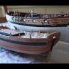
minimini reacted to jbelwood in Heroine 1838 by ggrieco - FINISHED - Scale 1:24 - Western River Steamboat as she appeared before hitting a snag in the Red River
Hi Glenn,
Been following your build from the beginning. Here's an idea I came up with for my water line hull
C.R.Lamb stern wheeler. As I wanted to picture her afloat in a water diorama this worked out
great. Most viewers don't realize what I did.
John
-
minimini reacted to AON in HMS Bellerophon 1786 by AON – scale 1:64 – 74-gun 3rd Rate Man of War - Arrogant-Class
Couldn't do anything through the week and not much progress today.
Made new keel pieces this afternoon.
I am very happy with these and will hopefully glue the paper on tomorrow and might get the sections together.
-
minimini reacted to mtaylor in Licorne 1755 by mtaylor - 3/16" scale - French Frigate - from Hahn plans - Version 2.0 - TERMINATED
Thanks for the likes and comments and following along.
You guys are going to make this decision for the next ship hard, aren't you? And I thought it would just be a simple decision.. Roebuck or something French like L'Orient. I figure why not go for tough ones....
John, the Roebuck also juxtaposes with quite a few American ships according to the history, as I recall.
A bit of an update... the rudder is ready for hanging. The macro shows the problems but in real life it looks pretty good to my eye. I actually had another one made but it hit the floor without my knowing it. The pup (hah!!!! at 3 years old, not a pup but she thinks she is) picked it up, and gave it back with unfortunately some deep teeth marks. I had to laugh as I call her "my helping bud".
Anyway, I've got blue taped into position while I sort out the irons attached to the hull.
As always, critiques, comments, or general mayhem is welcome.
-
minimini reacted to giampieroricci in L'Amarante 1749 by giampieroricci - FINISHED - 1:30 - French Corvette
I finally finished the inner lining of the sides with its endless and difficult to nailing the angle of the walled:
final sealing of hawses