


wefalck
-
Posts
5,558 -
Joined
-
Last visited
Content Type
Profiles
Forums
Gallery
Events
Everything posted by wefalck
-
 There are thousands of books, photographs, prints etc. on that site - after all, it is not just a 'site', but the digital portal of the French National Library! Don't look for ship's drawings, these are either with the Service historique de la Defence (SHD) in Vincennes (late 19th century to present) or with the Musée de la Marine in Paris (everything older than late 19th century).
 -
I think I would have left the exposed frames bare wood (protected with some sanding filler). Some builders put tar onto the frames for protection, but I am not sure that would have been practice at the Spanish coast. Coming on nicely ...
-
Yep, that's what I meant 👍🏻 These glow-head engines first developed in Denmark and the Netherlands for the fishing industry had to have long-strokes because the poor fuel they were designed to run on needed time to fully combust. Hence the low RPMs of around 50 to 150. They would literally run on any kind of liquid or semi-liquid hydrocarbons, such as rancid butter or seal-oil, though soot was a problem. One needed to start up the engine on something more flammable, such as alcohol or petroleum and then switch to the main fuel. The boats had two tanks for that purpose and sometime an additional tank on top of the engine to make semi-liquid fuels more liquid.
-
It appears that the pump was driven from the lay-shaft in the foreground of the lower picture. This has chain-wheel for an ordinary chain just inside the spill-head. This chain presumably led to the frame just port of the pumps, where there was a similar chain-wheel on a shaft that seems to drive an excenter, which in turn seems to have driven the balancier of the pumps. However, that balancier and the piston-rods for the pumps are missing. It is not very clear, but I think the cargo winch in front of the pumps was not driven from the lay-shaft, but traditionally via hand-cranks (missing). As I suggested in an earlier post, there was a sliding pinion that engaged the large wheel. In this way you had a two-speed winch: the upper spill-heads are driven directly from the cranks, while the lower spill-heads were driven through the gear-train, resulting in a mechanical advantage. There are two ratchet-wheels on the whinch, one oriented clockwise and the other anti-clockwise, so that one could use the winch in both directions. This kind of winch was universal on small cargo-vessels from the early decades of the 19th century on.
-
Well, the awns are there to grip animal furs or bird feather to help the seeds spreading ... I think some plumber's hemp, brushed straight, might be a more promishing option. I suppose you would get this in a DIY store (at least over here in Europe this is not a problem). The ridges of thatched roofs are their weak points and special techniques were develped in different cultures to overcome this. In some place pieces of turf were arranged along the ridges, fastened with wooden spikes, and grass and moss encouraged to grow there; in other places they used wooden boards, tiles, or in later years sheet-metal. On a boat, I could imagine that a piece of sail-cloth or similar could have been tied over the ridge. It would add to its improvised look 😉
-
Inexpensive Mill and Lathe
wefalck replied to JohnU's topic in Modeling tools and Workshop Equipment
Replacing some dodgy materials, such as plastic gib-strips can take you a long way indeed. And proper adjusting ... I went down a different route many years ago, but always found these modular system an interesting proposition, though 'combination' machines are not terribly useful, if you have the space and the money for a separate lathe and mill - very often you need to transfer parts from one or the other. However, you can create set-ups for specific machining operations that may not be possible or convenient with a standard lathe or mill. There are way of compensating back-lash, such as split leadscrew-nuts. The good thing is that once you have the machines, they can also make parts to improve themselves. The Austrian company behind these machines went through a lot of changes over the past few decades. Originally, they made the Unimat lathes. At a time they made the Unimat 4, they started to develop this modular lathe, which originally was called Unimat 1, but then changed the name to CoolTool, presumably to avoid confusion with the 'real' Unimat. The same company also served as an importer for Sherline machines and I think they were also branded CoolTool, at least for some time. Some 20 years ago I had conversations with them to buy some Sherline parts, but they had a quite high mark-up compared to buying directly in the USA. I think the trade law says, when something is assembled in country X, it become 'Made in X'. So legally it would be correct to claim 'Made in Austria', although the parts came from China. It's the assembler, who determines what quality is required from the supplier of parts and that is the key point.- 1 reply
-
- 1
-

-
On the 'attaching' itself, you would need to specify the period you are looking at, as the method and fittings for 'bending' sails developed quite a bit over the centuries ... it can also depend on the region for vernacular craft. Otherwise, yes, it is probably best to attach the sails to their respective yards, gaffs, booms etc. before these go onto the model.
-
It’s kind of a vane pump, a single vane with two valve-flaps. It’s fed through a suction hose (kept open by a metal spiral). There is a suction cage at the end, as would be used e.g. by the fire-brigade.
-
I just had a quick look at my pictures of GJØA in the museum, but today this winch is not present on her. However, normally there would be a pinion that engages with the large cog-wheel in order to effect a reduction and mechanical advantage. This may engage via a dog-clutch.
-
It is indeed vital to supply the engine with 'dry' steam, which is one of the reasons why I raised the issue of insulation in that earlier post. It would be possible to insert a water trap into the steam line, so that any condensation would be collected there, rather than entering the cylinders, and drained by the engineer from time to time. The problem of condensation is particularly important when starting up the engine from cold. Condensation is inevitable in the cylinders, which is why they are supplied with drain-cocks at both ends (for double-acting cylinders). Not sure, how they would be operated on the steam-boats, on locomotives, traction engines and the likes, there was a system of connecting rods leading to the driver's stand. Once up and running, condensation is probably less of a problem, unless it is really cold outside or the boat is moving only slowly.
-
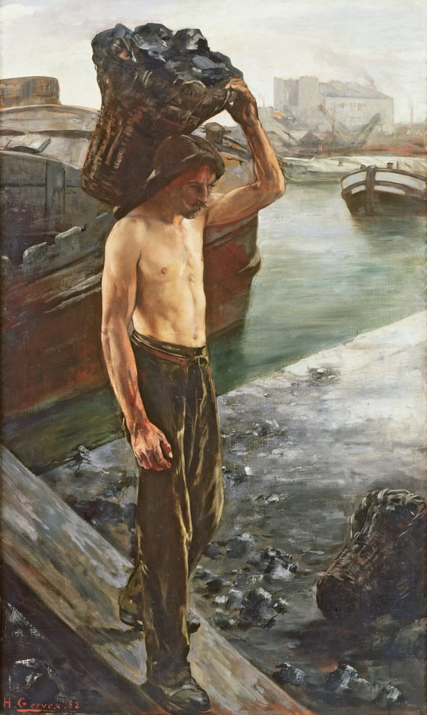
I gather there are textbook data for coal consumption per fire-grate area or amount of steam generated per hour. This machinery probably was not terribly efficient energetically, low-pressure boiler, long-stroke/low-rev engines, heat losses in the pipe-work, etc. Depends also on the calorific value, i.e. quality of the coal. I would gather that she would need several tons of coal per day. I think each sack would have weighed 80 to 100 pounds - tough guys the coal-carriers those days. I remember them carrying such sacks on their back, when we still had coal delivered to our house. Source: https://www.meisterdrucke.uk/fine-art-prints/Henri-Gervex/41701/The-Coal-Carrier,-1882-.html
- 259 replies
-
- 10
-
-
Over here in Europe at least, coal was traditionally delivered either in large wicker-baskets or in jute-sacks. Perhaps it would have been the easiest to just keep the baskets standing on deck? Unlike in seagoing ships, there probably wasn't much rocking and rolling on the river, so no worries that the fuel might go overboard.
-
I tend to rub bare metal parts, particularly when they are supposed to be cast-iron, with a soft pencil. You could still follow your idea to sort of make some dashes on the rim of the ratched wheel.
-
I can see the point of having the boiler forward on boats destined to operate on tropical rivers, but in areas, where temperatures may be rather low (but not that low that the river freezes over), the long steam-pipes must have caused a lot of power losses on the way to the cylinders. There doesn't seem to be any insulation? On the other hand, having the boiler under one's feet might have been appreciated in the pilot house in winter.
-
You could simulate the metal hardware by painted paper strips ... For the ratched wheel I wouldn't use cardboard, this has the tendency to fuss when worked with something else, but a sharp knife. On the other hand, you could draw the profile of the wheel in a suitable drawing program on the computer, print it out and stick it to a cardboard disc; then take a sharp cutter and cut out the spaces between the teeth. I suppose the prototype ones would have been rather rustic ...
-
Perhaps I didn't actually look to closely at the beginning, I didn't realise that this is a boat with hard chines. In this case the stringers, kind of serving as landing for the next strake make perfect sense. In fact, there are also carveel building techniques, where the individual strakes are joined by interior stringers. I think this is actually a rather old technique, practiced since antiquity in the Mediterranean. They both, reinforced the construction and ensured watertightness. In the Nordic countries laths were used to hold down the caulking of moss in some types of boats.
-
Allen is right, as the stringers also serve as 'shelves' for the thwarts normally. I have seen, however, clinker-boats, where the bent-in frames do not touch the planks along their whole width.
-
Copper was quite expensive in the old North, but they had plenty of bog iron inter alia. To my knowledge these ships were always iron-fast. In fact, for some of the famous boat finds, the nail pattern is the only thing that was found, the wood has long be decomposed.
-
A DIY thickness sander
wefalck replied to Kris Avonts's topic in Modeling tools and Workshop Equipment
And, so ? -
Thatching in Europe and Japan is a serious business and the workmen take great pride in its execution to ensure that it is watertight and its longevity. I think thatching with straw is rarely practiced anymore, but in some areas of Europe (for instance, the Cotswolds in England, northern Germany, Denmark, ...) it is still practiced with reeds. It's expensive and fire-insurance premiums are high, but people like to preserve the traditional appearance of their houses. I happen to have a little booklet about thatching practice in England and watched it in execution on the building of a museum near Hamburg, where an uncle of mine was a volunteer. Model railway guys predominantly reproduce reed-roofs, which have a geometrically quite well-described shape and a uniform surface. I gather, the 'gaming' modellers, who work on medieval subjects, may have techniques for roofs thatched with straw. However, they tend to work in a somewhat exaggerated 'cartoon', rather than naturalistic style. I could imagine various routes to reproduce such thatched roofs. Next time you are down Mexico-way, you could try to find some dry grass, hammer it to break the fibers and comb it with a bristle-brush to remove small and loose bits. Alternatively, you could try to find some plumber's hemp and also brush it to straighten out the fibres. I would then put two strips of self-adhesive tape in the distance of the scale-length of the stalks, lay out the fibres in not too thick layers and spray them with some matt varnish to lightly glue them together. Once dry, you can cut swaths of this 'thatch' and glue them in rows onto the lattice work, beginning from the bottom. Normally the thatch is 'sewn' to the lattice work and you could reproduce that.
-
After-thought-job well done! It's those details that really make the difference. It's not easy to have all the necessary foresight, but I make myself a mental plan for working 'inside-out' in order to minimise interference. It does not always work though 😬
-
Pulled the Trigger == Lathe coming
wefalck replied to kgstakes's topic in Modeling tools and Workshop Equipment
I have been subscribed to both channesl for years ... 'clickspring' is a genius with handtools, particularly the file. The Taig is sold in the UK/Europe under the name Peatool, btw., but https://www.cartertools.com is indeed a useful site and I got lots of ideas from it over the years though I don't have a Taig. Although I was lucky to get some basic lathe instruction from an old mechanic, who ran the hobby-workshop (equipped with outdated toolroom machinery that the Swiss precision industry donated) at my university, it was not until many years later that I could afford my own lathe. I got myself various apprentice text books from the 1940s/50s (before CNC creeped in) to learn the basics, De Carlè's book (The Watchmaker's and Model Engineer's Lathe), as well as various historical mechanic's handbooks. The latter are good, because they contain useful ideas for manual lathe work and work-arounds that by today's mechanics (and H&S officers ...) may be snuffed upon or are considered inefficient (such as grinding your own HSS lathe-tools).
