wefalck
-
Posts
6,660 -
Joined
-
Last visited
Content Type
Profiles
Forums
Gallery
Events
Everything posted by wefalck
-
 That could be an interesting proposition to imitate these ramshackle (litterally) arrangements. It will have to be complemented by a worn appearance of the boat overall, to look credible and not just like a botched-up modelling job 😲 Externally stropped blocks would be a lot easier to make ...
- 312 replies
-
- 4
-

-
- Chile
- Latin America
- (and 6 more)
-
SMS Karlsruhe by Wreck1919 - 1/100
wefalck replied to Wreck1919's topic in - Build logs for subjects built 1901 - Present Day
Actually, the three chain would not be visible from that angle, the would be too low in the boat I think 😉 'Spannschraube' is normally translated as 'bottle-screw', because in its closed form it resembles a bottle. -
These would have situations and scenes in small-scale cargo shipping all around Europe (and probably the N-American continent too) well into the first years of the 20th century, when better roads and lorries replaced the boats. However, over here in Europe it was common to have a small coal-stove forward, which was used for cooking and heating. It is very easy to draw too much deck camber, I just had this experience myself and needed to correct the drawings for my new project. The camber also depends on how a boat is worked. Particularly when a lot of work is expected on the deck, less camber makes it easier to stand on deck. Also, when one expects to carry deck-loads, that is made easier with less camber. It's a trade-off between water-shedding capability and working convenience.
- 312 replies
-
- 5
-
-
- Chile
- Latin America
- (and 6 more)
-
Thresher & stable engine by RGL - FINISHED - Plus Model - 1/35
wefalck replied to RGL's topic in Non-ship/categorised builds
Nice ensemble! What's a 'drip' in this context? -
Zero Clearance for Table Saws
wefalck replied to DelF's topic in Modeling tools and Workshop Equipment
Never though of using a tape over the table as zero-clearance 'insert', that sounds like a clever idea. While creating a zero-clearance cover with a table saw on which the blade can be raised, this is not so straightforward for saws with fixed blade (such as small PROXXON). Have to think about a solution ... perhaps just a strip left and righ of the blade.- 12 replies
-
- 6
-
-
- Zero clearance
- table saw
- (and 1 more)
-
It seems that a lot of of the combustion gases just blow out, rather than propelling the round. This would greatly reduce the recoil and make it 'softer' in comparison to a modern gun.
-
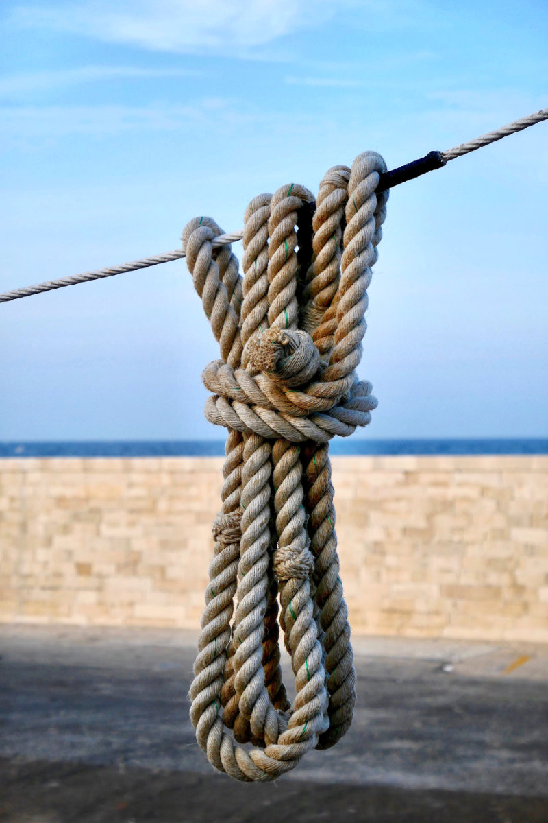
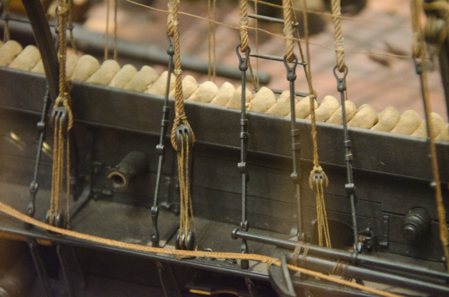
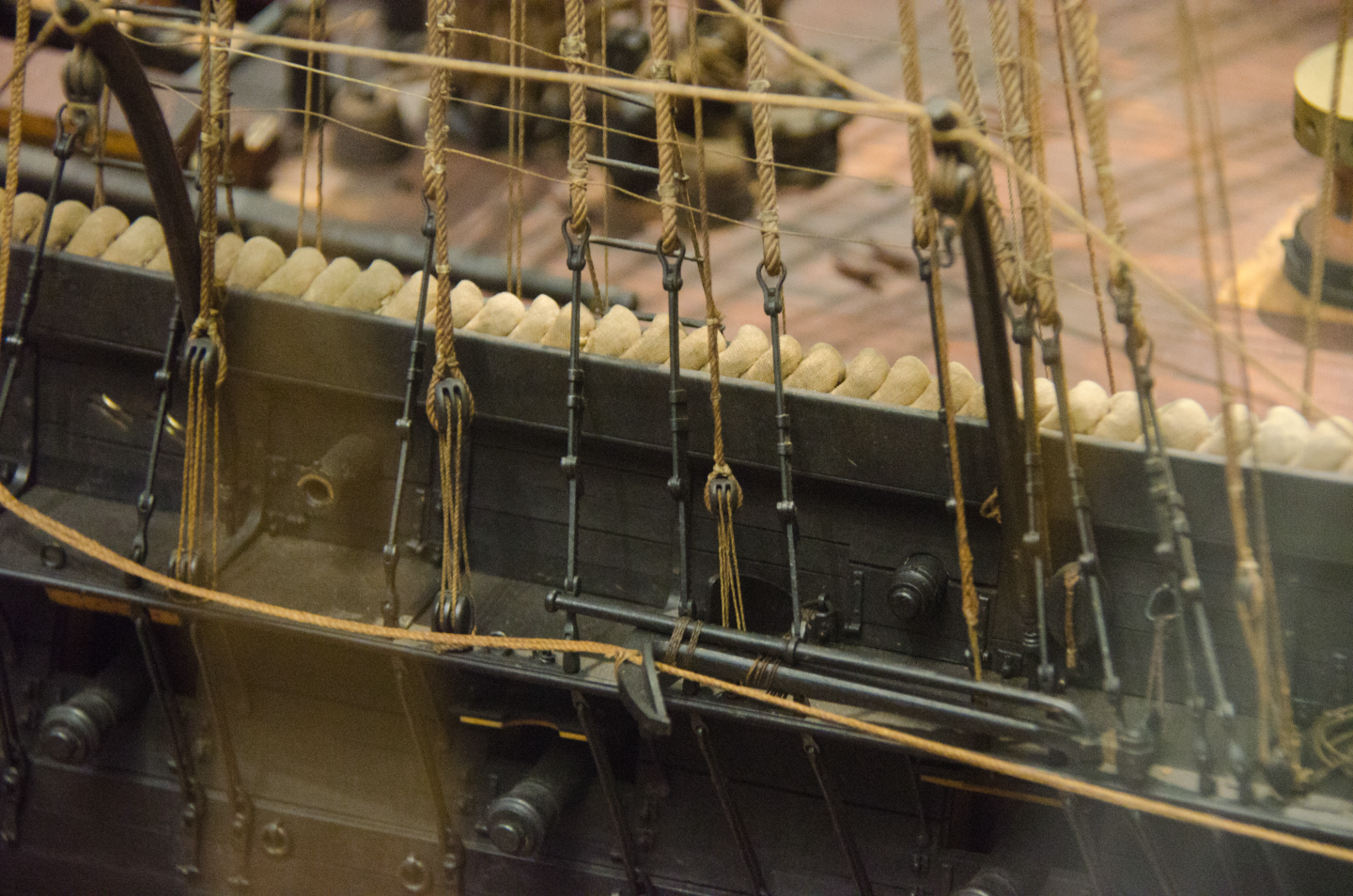
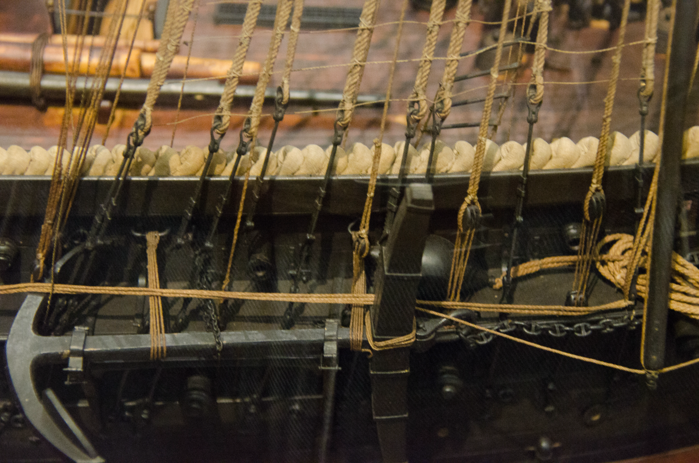
Very good recovery. I don't have Peterson's book, but believe that he based it on 18th and early 19th models in the Maritime Museum in Stockholm. There was no wire rigging at that time. By the end of the 19th century, after wire-rope had been introduced some 30 years earlier, rather than being taken around the deadeye, they were taken around solid thimbles. Normally, bottle-screws then would be used, but I gather they used a combination of old and new style on GJØA because bottle-screws can freeze solid, while with deadeyes and lanyards, one may still have a chance to tighten them. Also, they are easier to replace, when you don't have any supplies.
-
Fantastic results in obviously difficult times 👍🏻
-
Help with depicting extra line on bitts
wefalck replied to usedtosail's topic in Masting, rigging and sails
Of course, it your model and you can do whatever you like to it. But be aware that others may follow bad examples as you are about to do. Rather than making test-rigs for historically inaccurate arrangements, the time would have been better spent on doing some research. Sorry for being a bit blunt and harsh, but I just cannot understand, why people are so obstinate to follow down an obviously wrong path. This plan view copied from above is obviously only a partial view and, as we don't have the plan, we don't know what the numbers refer to. However, the lines leading to nos. 58, 59 and 60 lead to some dots on the horizontal member of the bit, that I woud interpret as holes for belaying pins. If you drill some holes here and install some pins, you may not have necessarily historically correct solution (which would need to be confirmed by resarch), but at least one that is technically correct ...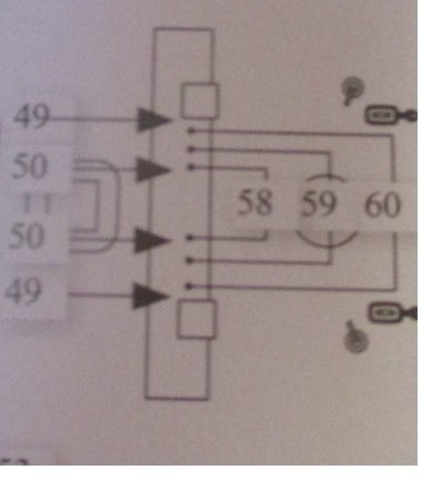
-
Have a look at @archjofo's building log on his CREOLE. I think he serves 'ropes' down to 0.3 mm diameter on a shop-made serving machine. I agree, that most commercial serving machines seem to be too 'coarse' for such delicate jobs. On the other hand, @dafi recently used PVA to simulate (partially) served rope on his 1/100 scale VICTORY. A totally different route I have been using for served strops is silk-spun copper wire as used in high-frequency coils of old radios etc. For many years it was difficult to find, but as old-fashioned electronics and restauration of radios has become fasionable, such wires re-appear on the market again. I used inherited wires or stuff I picked up on flea-markets and consider using it for my next miniature project.
-
Help with depicting extra line on bitts
wefalck replied to usedtosail's topic in Masting, rigging and sails
I fully agree with @Dr PR ... Belaying lines that have a constant load on them on these horizontal bits shows actually a lack of understanding of the functioning of belaying. As long as you keep the running end under tension, the friction on a belaying-pin, cleat or bollard from half to one turn of rope is usually sufficient to carry the load. This fact is used to safely undue the belaying. The final turn and half-hitch are only there to secure the rope when there is no tension on the running end. Assuming that a line comes running down from the mast, it woul have to go either a quarter turn or one and a quarter turn around the bit in order to arrive in a position from which you can pull on it. A quarter turn is not sufficient and one and a quarter turn is too much to be workable. When belaying, you would need to take the running end around the horizontal bit again to form a clove hitch, which is very difficult to do under such conditions. A clove hitch would be more or less the only hitch the works under such circumstances, but is difficult cast off, when there is tension on the ropes. So, from a practical point of view this is a no-no. Again, rather than copying the mistakes of other modellers, it is better to undertake some research oneself. I realise that the literature, both the contemporary and modern works, are weak on belaying points. However, there are certain common practices in any one country that do change much from ship to ship. Seamen were transferred from ship to ship and had to quickly find their way around a new ship and you cannot 'try' several ropes to find the right one at sea. So on all ships certain types of ropes were belayed more or less at the same location. This may vary, of course, depending on the rig and the size of the ship. -
Thresher & stable engine by RGL - FINISHED - Plus Model - 1/35
wefalck replied to RGL's topic in Non-ship/categorised builds
I am a totally urban person coming from totally urban backgrounds of all my ancestors 🤓. Perhaps, that is why I was always interested in such agricultural subjects ... The German (Technical) Museum in Munich has a replica of the first horse-drawn mechanical reaper of 1831 by McCormick: The basic operating mechanism for cutting has not changed much since. Anyway, back to the practicalities of modelling: for the leather driving belts I would cut narrow strips of thin paper of the apropriate width, lay them out on a (card)board covered with cling-film and give them a liberal coat of paint on both sides. When putting them around the sheaves, the seams can be hidden underneath the pulleys out of sight. On the prototype, the belts would be stitched together using metal clips not unlike paper staples. Sometimes they were also laced together. The belts were also treated to make waterproof, but I don't remember with what, as they shouldn't become slippery. Remember that the belts workd through the friction between the leather and the cast-iron and are not normally tensioned fully. The amount of pulley surface around which they wrap is more important. Such pulleys are actually not flat, but slightly domed - it may be counterintuitive, but this is what keeps them centered on the pulley. There are some videos on YouTube that show such belts in action.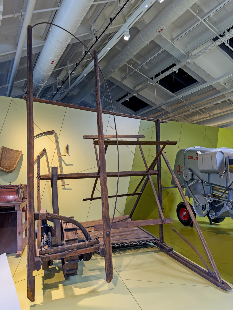

-
Help with depicting extra line on bitts
wefalck replied to usedtosail's topic in Masting, rigging and sails
I would toss those plans, don't look at what other modellers did, but go back to period written sources and perhaps period models (cum grano salis) in order to work out the proper lead of lines and a proper belaying plan. To me this seems to be the only reasonable solution. BTW, it is not uncommon that two lines that would have to be worked at the same time would go onto the same belaying pin. -
Help with depicting extra line on bitts
wefalck replied to usedtosail's topic in Masting, rigging and sails
Allow me to disagree. Unless everyone here misunderstood the question, I think all the answers are there. The problem may be that lines are not normally belayed on bits (see post #2 by @popeye2sea, unless the bits are provided with belaying pins. If that belaying point were correct, there may be a somewhat haphazard solution in coiling up the rope in a 'bunch' and wedging it between two lines coming down. That would be relatively secure. On yachts such bunches are commonly wedged between the mast and say its haliard coming down onto a clamp. Random image off the Internet of a rope tied up to a bunch. However, such a method would be more time-consuming to cast off, as first the bunch has to be untied. One would only use this for lines rarely moved.
-
'Just' rolling barrels at sea would be a major hazard ... all loads have to be securely fastened by wedging them in place, regardless whether they are stored upright or horizontal.
-
Help with depicting extra line on bitts
wefalck replied to usedtosail's topic in Masting, rigging and sails
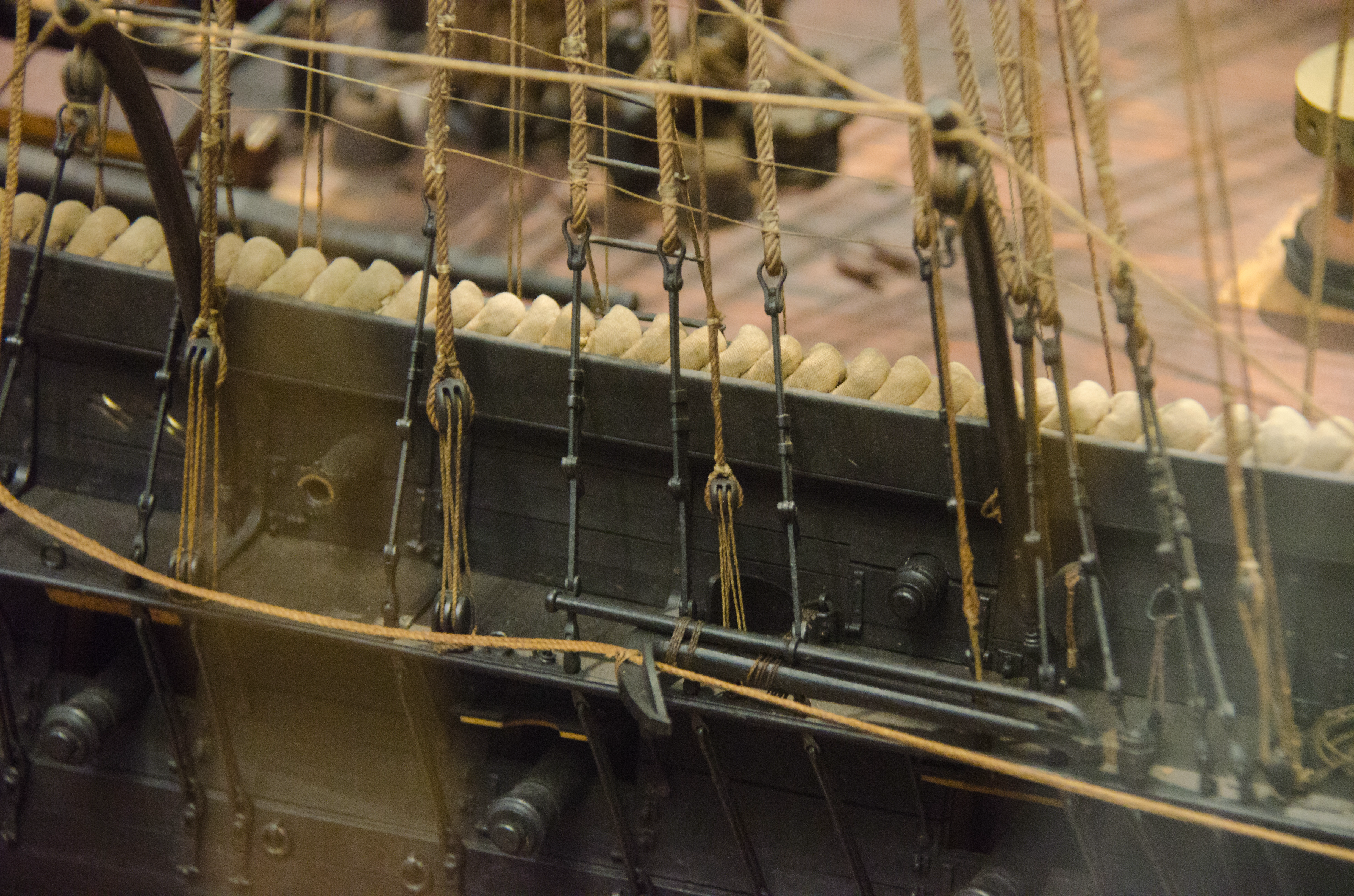
... that's why everything has to be tidied up as quickly as possible 😉 I would not call this 'extra' or 'excess' lines. Each rope has to be long enough to pass through the tackle in its most extended position, plus 'extra' (here it is justified) length for a sufficient number of men to haul on it. On a model, one would measure this total length, install it, belay it, secure it with a drop of varnish, and then cut off the length beyond the belaying point. This length then is coiled up appropriately and hung with one loop over the belaying pin. It is a good idea to wet the coils in situ with a bit of thinned varnish and hold it down in a most natural drape as possible, while the varnish dries. You can see this clearly on the right side of the fife-rail behind the mast of SAN DIEGO in the above photograph. In this way the line can be cast loose very quickly and many coils can be arranged next to each other. -
I think ChatGTP is trying to humour you 😉 Joking aside, it is good to see that ChatGTP begins to be trained now also on niche subjects like ours. When I tried it a few months or so ago (I use it professionally from time to time ...), return on maritime history subjects were trivial and very generic.
-
I think the term 'sanding-sealer' doesn't really mean sealing the wood hermetically. It at all this could only be achieved with a glazing that is impermeable to water vapour. Also, I find the term 'finish' confusing or misleading, as it can mean different things, ranging from the material used to the degree of sheen. In classical French polishing one tries to achieve basically two things: the depth of colour that comes from the light penetrating into the pores of the wood and not being reflected from the surface, as described above, and a smooth, possibly glass-like and shine surface. Traditionally, this was achieved by rubbing the wood with blocks of pumice between the application of shellac in increasing 'cuts', i.e. shellac to alcohol ratios. That's how Roentgen or other known 18th century furniture builders would have achieved their glass-like surfaces. Today, one can buy suspensions of pumice or talkum in solutions of shellac (or some other type of varnish) as 'sanding sealers', which is good enough for many applications. And you don't need to take the process of 'French polishing' to the end, but stop at a point that is good enough for the purpose of the model. The fact that shellac will always be redissolved in alcohol can be used to advantage in various applications: you can use it as reversible cement for instance. Shellac simply dries by the evaporation of the solvent, while other materials, such as line-seed or tung-oil, polyurethane varnishes etc. undergo a polymerisation that makes it difficult to impossible to redissolve.
-
Thresher & stable engine by RGL - FINISHED - Plus Model - 1/35
wefalck replied to RGL's topic in Non-ship/categorised builds
Coming back to the subject of modelling as such, I think I found a good solution for simulating blank cast-iron parts, such as the surfaces of pulleys, and also the steel tyres on cast-iron wheels : I first run them slowly on the lathe (or a hand-held drill) and smooth the surface of the plastic part with very find wet-and-dry sandpaper. For cast-iron I then spray the part in black and for steel I spray in some silver or 'steel' paint. The next step is to rub a soft pencil on the surface and burnish this with either a cotton-stick or one of those paper 'smudging' sticks artists use. I think the results are quite convincing: This is a Fowler Z7 ploughing engine in 1/72 scale on the basis of an old KeilKraft kit that I made some 35 years ago.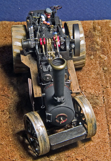
-
Thresher & stable engine by RGL - FINISHED - Plus Model - 1/35
wefalck replied to RGL's topic in Non-ship/categorised builds
Today in Europe combine-harvesters are usually owned by contractors or by a cooperative of farmers. You need quite a few hectares to amortise one. In pre-War Eastern Europe there were often large land-owners (landed gentry) that farmed almost at industrial scale and had their own machinery, sometimes even narrow-gauge field-railways to transport the produce. -
I suppose this depends on the circumstances: would it be full load or only a few barrels, how long would the trip be and in what kind of waters? Stowing barrels horizontally would almost certainly a better use of the space and safer on longer trips. The barrels would be wedged in place. It also depends on the size of the barrels and how many crew would be there to man-handle them. On the other hand, shipping a few barrels from one port to another in reasonable weather conditions may not require a lot of stowage effort. Turning over barrels from vertical to horizontal may be quite an effort, depending on their size. There are different techniques for getting barrels in and out of a ship, depending on the availability of loading equipment. Cranes were not very common in small Mediterranean ports, I think. In addition, a fee would be due for their use. A classical method for getting a barrel out of a hold and onto a quay would be with the aid of two ropes that are fastened on the quay at a distance a bit less than the length of the barrel; the rope would be then taken around the barrel and several men would pull on the ropes, effectively rolling the barrel out of the hold and up to the quay. A plank could be used to aid this process. If there was a crane or one could use the ship's boom, the drum would be attached either vertically with a drum-sling or horizontally with two griping hooks.
-
Thresher & stable engine by RGL - FINISHED - Plus Model - 1/35
wefalck replied to RGL's topic in Non-ship/categorised builds
All over Europe, threshing contractors were going around from farm to farm (as were ploughing contractors), as buying threshers (or steam-ploughing sets) would not be economical for individual farms. -
While searching for something else in my picture archive, I came across a couple of pictures of mechanism used for tensioning the shrouds on BELLE POULE. I took them some ten years ago in the museum on request by someone:
- 62 replies
-
- 3
-
-
- belle poule
- OcCre
- (and 1 more)
-
By coincidence, I was writing a journal review for the German LOGBUCH of SKYLLIS no. 23 (http://www.deguwa.org) and there is an article on how one can conclude from the type of barrel used in 17th century Netherlands: Oosterbaan, J. (2023): Identifying Content through Casks.- SKYLLIS, 23: 103-116. It seems that the Dutch guilds of coopers had gauges for each type of barrel and these gauges have been preserved in museums. The author focused on trade barrels for herring and beer.
-
Beginner - Rigging Tools
wefalck replied to nheather's topic in Modeling tools and Workshop Equipment
Apologies for slightly disagreeing with the last suggestion. It seems tempting to use a tool to pull rigging line through a block. However, if a folded line can pass through the hole, the hole is too big for the line. If you look at prototype blocks, you will see that the sheave is only a fraction thicker than the rope it is meant for. There is very little clearance betwen the rope and the block. Thus, not really a tool but rather a material is some fast-drying solvent-based varnish with which one can stiffen the end of lines to fiddle them through blocks. The same varnish can also be used to secure splices and knots. Some people use CA cement for that, but I would advice against it, because it is messy and you cannot dissolve, if needed, afterwards. Knots secured with varnish can be unravelled with a drop of varnish, which you may find helpful.