wefalck
-
Posts
6,648 -
Joined
-
Last visited
Content Type
Profiles
Forums
Gallery
Events
Everything posted by wefalck
-
 I think what was meant was, that the longitudinal seams between the planks in the second layer should be in the middle of the planks of the first layer, not overlapping within a layer. Personally, I think that POB construction where the spaces between the bulkheads are filled in makes for much easier and successful fairing. Any fairing errors not corrected before a first layer of planks will transmitted to the second layer, so that there is no real advantage. Of course, when you are working from a pre-cut kit, where the dimensions of the bulkheads assume two layers of planking, you cannot avoid this extra work. When the bulkheads have not been cut already, you could add the thickness of the layer by drawing a parallel line and saw to this line.
 -
Yes, life it too short to build the same ship twice ...
- 128 replies
-
- 5
-

-
- zulu
- sternwheeler
- (and 1 more)
-
I have never travelled 3rd class on any railway - this had long been abolished in my part of the World. However, trams used to have similar seats (on some older trams e.g. in Vienna they are still in use today, I believe) and I found them more comfortable than many modern plastic seats, particularly when the latter are formed like the negative of your bottoms and only allow you to sit in one position. I gather, the 2nd class seats are only better than the wooden ones as long as they are not sat through ... I am not a railway expert, but would agree that bogies look rather high. I wonder, whether there are not any drawings of these coaches to be found on the Internet for verification.
-
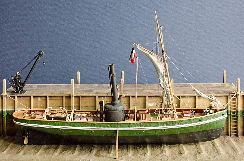
I think a water barrel or tank would have been there. The water in the boiler gets consumed quite quickly and one needs to keep a certain level in order to not burn out the flue-pipes. Otherwise, I would think that the operators of these pile-drivers would have had either a barge for coal and water at hand or would have carted the supplies to the drivers (as did the operators of steam-rollers and traction engines). The buffer barrel/tank could be filled by hand-pump, while the coal could be carried on board in sacks (on the back of hired men) or in wheel-barrows. In those dark ages before HSE, a simple plank would have been sufficient to be laid to the land.
-
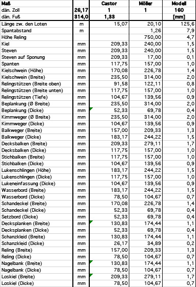
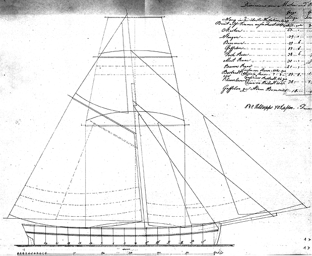
Design of the model The idea for the project was conceived back in around 1980, when I became aware of the 1934 book by Szymanski and the drawings therein. Unfortunately, the tracing of the original builder’s plan for the purpose of the book was done very summarily and all the usual details are missing. I could not locate the original drawing, as it must have been in the possession of the builder’s family at the time and is probably lost now. Lines and sail plan of a Rahschlup, drawn in 1852 by H.P. Steffen, Lübeck (from Szymanski, 1934) Then in the later 1990s I discovered the drawings by Joachim Möller in the archives of Rostock Maritime Museum, who kindly provided me with copies. After a lot of procrastination and detours I started the S.M.S. WESPE project, which took much much longer than anticipated. In between, I made several attempts to redraw the lines for the purpose of model reconstruction. My oldest files are still in ClarisWorks … As I am now trying to recuperate the work I did several years ago, I found it somewhat difficult to remember what I did at the time and what my intentions were for construction. The drawings by Joachim Möller allow to take off a few key dimensions, but it does not give the dimensions of the scantlings. However, the measurements taken by Nielsen (1973) off the jagt CASTOR (1867) give a basis for extrapolation. CASTOR was 48’ between the perpendicles, as opposed to 64’ for the Rahschlup. It is not known, which foot Möller used, it could have been the Mecklenburg or the Rhineland-Prussian, which was in widespread use and is identical to the Danish one at 314 mm. For convenience sake I assumed that it was that latter. Based on the (crude) assumption that all parts are proportionally bigger in the bigger ship, I developed a conversion table that shows the upscaled dimension and the dimensions in the chosen 1/160 scale. Conversion table that calculates the scale dimensions for the reconstruction The construction will be plank-on-bulkhead for a waterline model. Unlike for larger ships, the bulwark stanchions were not separate members, but every second or third frame was extended up to the level of the main rail. Such practice can be seen e.g. in Klawitter (1835). In terms of model construction, this has the advantage, that the hull shape up to the main rail can be easily defined. On the other hand, the body plan does not give all the necessary frame positions, which have to be lofted off the line plan. Likewise, the cant-frames in the bow that reach up to the rail have to be lofted. Contrary full-scale practice, I will also introduce ‘cant-frames’ towards the stern to avoid excessive fairing and bevelling and being able to use one thickness of material (see below). I did quite some lofting in my 2D CAD in the past and now have to go through my older files in order to understand what I did some years ago and how far I actually got. I tended to work on this during vacations, when I had no access to the workshop. I also realised that more lofting needs to be done on the cant-frames. The plan is to cut the bulkheads from 1 mm acrylic glass, which then will be slotted into a solid baseplate of 3 mm acrylic. The slots will be cut in the milling machine. The stem will also be 1 mm acrylic and its final thickness build up with outer layers of styrene in order to be able to create a rabbet without the need to mill it into the solid acrylic. The rationale behind using acrylic glass (Plexiglas) is, that it is isotropic, does not have grain, and holds edges very well. In addition, this material was already in my storage, while sourcing good-quality hardwood (e.g. boxwood) in suitable dimensions is difficult, where I am. Also, Plexiglas does not generate dust, when milled etc. and thus is more friendly in a workshop that is one corner of my study. That is how far the planning and the work have preceded to date. Now back to the drawing-board – or rather the CAD. To be continued
-
Bragozzo by maurino - FINISHED
wefalck replied to maurino's topic in - Build logs for subjects built 1901 - Present Day
Did the bragozzo really have shrouds? In many cases with lateen rigs the haliards of the antenna seem to serve as shroud. -
Sounds like a lot of hand-filing to come on the propeller blades ...
-
I gather vertical boilers were designed to raise steam quickly and don't need good foundations, as you would need for a locomotive-type boiler. And I don't think that fuel-efficiency was a major concern under those circumstances. To me the boiler actually looked a bit small, but then I don't know how many horse-powers sustained one needs to drive one of those pile-drivers. Good start on the machinery 👍🏻
-
I am always perplexed by the complexity of the shape of some parts. Do they use some sort of templates to (rough) cut the pieces and fit them then?
- 174 replies
-
- 1
-
-
- Vigilance
- Sailing Trawler
- (and 1 more)
-
Nice sculpting indeed! Somehow I had the same experience with 'Greenstuff'. It didn't seem to stick to polystyren figures, which I used as a basis very well at all. Got some, as most figure sculpturers seem to use it and I have seen great results with it. Perhaps it is a matter of technique? I don't do sculpting very often. Some people use twisted wire armatures, to which the sculpting material should adhere a bit better. On the other hand, this means a softer armature.
-
What is the scale?
-
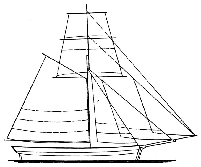
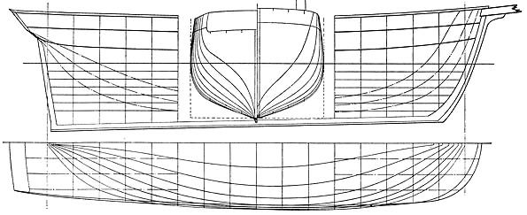
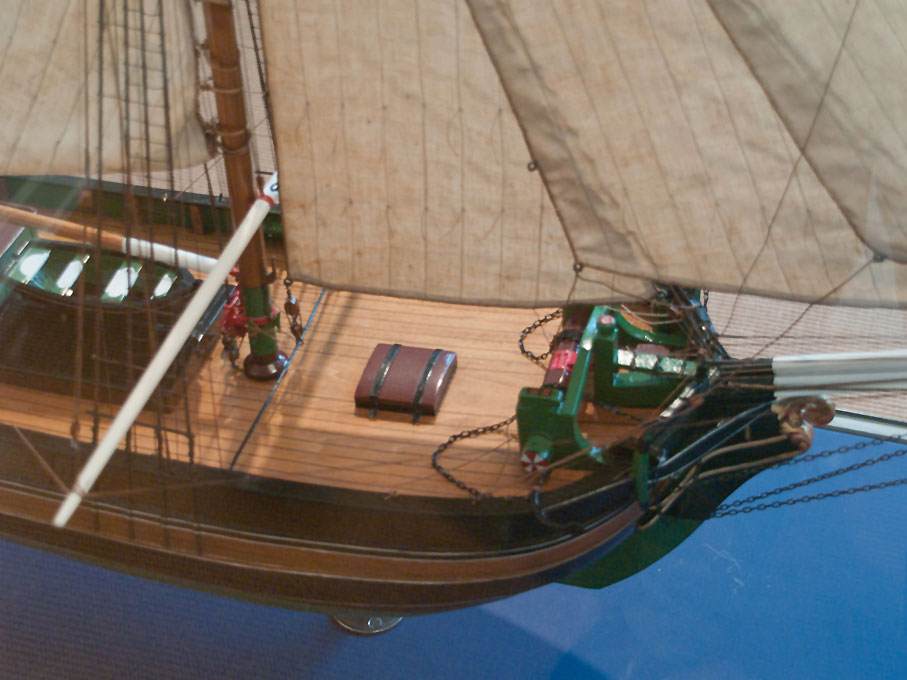
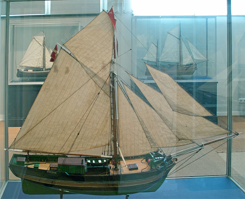
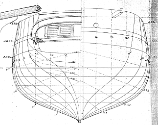
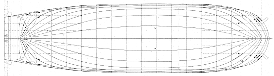
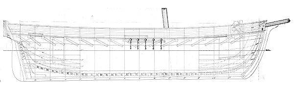
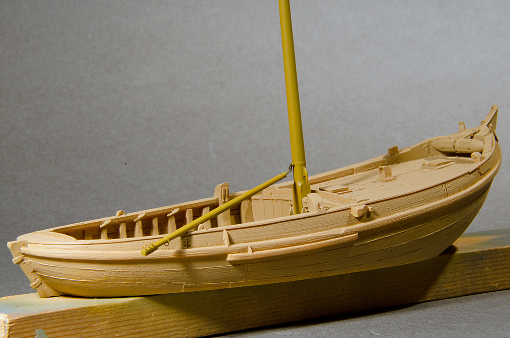
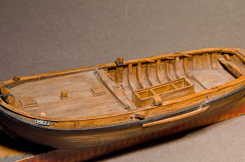
Thanks for your initial interest! ******************************* The basis for the model reconstruction The model will not depict a specific ship, rather the reconstruction will be for the ‘type’, based on a set of drawings by a Joachim Möller (who was a builder in Rostock) dated to 1846 and preserved in the archives of the Rostock Maritime Museum (https://schifffahrtsmuseum-rostock.de). It is not known, to which ship, as they were not named, nor was a client indicated on the drawings. Sail plan and lines drawings of a Rahschlup drawn by Joachim Möller, dated 1846, Schiffahrtsmuseum Rostock. They follow the practice of the time and give line and body plans as well as side elevation/longitudinal section and a sail-plan. This allows to reconstruct much of the deck-layout and the dimensioning of the visible woodwork. The sail-plan also contains a table with the spar dimensions. Much of the details of the deck, the rigging and other fittings will have to be reconstructed from contemporary paintings and photographs of similar craft that survived into the late 19th or even into our times. A valuable source of information are the books by Friis-Pedersen (1980 and1983), and Funch (1833 and 1846). Interestingly, the water-colours by Friis-Pedersen reproduced above show a Rahschlup virtually identical to that of the plans by Joachim Möller, but I doubt that Friis-Pedersen had access to these drawings, which were located in the GDR at the time. General information on contemporary building practice in Germany can be found in Klawitter (1835) and Steinhaus (1858), which bracket the time, when this Rahschlup was designed. Masting and rigging details can be obtained from Bobrik (1848), Biddlecombe (1848), and Steinhaus (1869). The two Danish jagt measured by Nielsen (1973) give details on dimensions of scantlings and other parts, which are useful for upscaling. One should also not forget the detailed drawings of a Danish jagt in the ‘Souvenirs de la Marine’ by Pâris. Other more or less contemporary (text)books on shipbuilding and rigging will be also consulted, but with caution, as they typically reflect the practice in larger ocean-going vessels. However, tables on spar and rigging proportions are still useful. Various useful resources No Web-site covering this type of coastal craft could be found yet (apart from my own). There are, however, some sites that feature a Jacht, jagt (Danish), jakt (Swedish) or slup (Norwegian, Swedish) under restauration. The most interesting site was the one documenting the restoration of the small Norvegian slup RUTH (1854, https://www.sluppenruth.dk), however the many photos of the process seem to have disappeared from their Web-site since I downloaded them five years ago. The restoration project for the Danish Jagt 'JENSINE AF HADERSLEV' (https://www.jensine.dk) from 1852 is also interesting, because the photographs show many original details of such and the steps of reconstructing unsound or missing parts. It should be noted that all these restorations altered the original deck-layouts with a view to accommodate the needs of cruising vessels and modern safety at sea requirements. A replica of a Danish Jagt has been constructed at the museum shipyard of Flensburg on the basis of the lines of the DE FIRE BRØDRE (1794), whose lines are reproduced in NIELSEN (1973). Unfortunately, their Web-site does not give any details on this project beyond the launch that took place in 2009. Pictures of her construction can be seen here:https://www.arbeitskreis-historischer-schiffbau.de/mitglieder/ontour/flenswerft/. The Altonaer Museum in Hamburg has a fine collection of models of small 19th century merchant sailing ships. These models were constructed in 1/24 scale between 1909 and 1912 from plans in the museum collection and plans on loan from various shipyards of the region (Timmermann, 1974) by a boatbuilder, a blockmaker and a sailmaker. While these models are not contemporary to their prototypes, their builders were presumably close enough to the time to have reproduced reasonably well the then current practices of construction and rigging. Below are two pictures of the Schlup ELBE (1836). More pictures of these models can found at https://www.maritima-et-mechanika.org/maritime/hamburg/altona.html. Model of the Schlup ELBE (1836) in 1/24 scale. Built by D. Behrens in Schulau (near Hamburg) for Hans Oestmann (Inv. Nr. AB 1813, Altonaer Museum, Hamburg) Over the years more and more museum holdings in terms of drawings and paintings have been digitised and made available through the Internet, namely those of the (maritime) museums of Denmark, Norway, and Sweden. This allowed to consult numerous paintings of Norvegian and Swedish slups and Danish jagts. Literature As for graphical resources, most of the literature listed below has become available as digital copies over the past 20 years, which allows to consult even rather rare books remotely. BIDDLECOMBE, G. (1848): The Art of Rigging.- 155 p., Salem, Ma. (Reprint 1990 by Dover Publication, New York). BOBRIK, E. (1846): Handbuch der praktischen Seefahrtskunde.- Vol. 1-7: 2688 p., 50 pl. Zürich/Hamburg (Julius Fröbel & Co./Hoffman & Campe). Chapman, H. Af (1768): Architectura Navalis Mercatoria.- 103 pp., Rostock (Reprint 1968 at VEB Verlag Hinstorff). Fleischfresser, K., Hoffmann, R. (1975): Segler von Haff und Bodden. Pommersche Küstenschiffahrt.- 96 pp., Hamburg-Norderstedt (Verlag Egon Heinemann). [Friis-Pedersen, J.] (1980): Sejlskibe - Danskbyggede traeskibbe opmålt, tegnet og fotograferet.- Handels- og Søfahrtsmuseets på Kronborg Søhistoriske Skrifter IX: 107 pp., København (Høst & Søn). [Friis-Pedersen, J.] (1983): Sejlskibe - Nordiske fartøjer opmålt, tegnet og fotograferet.- Handels- og Søfahrtsmuseets på Kronborg Søhistoriske Skrifter XI: 96 pp., København (Høst & Søn). Funch, D.H. (1833): Praktisk Skibbyggerie. Et Forsøg.- 76 folding (some are quite large) lithographed plates, including 28 in full color & many others tinted or heightened in color. 76 pp., 1 leaf of errata; 64 pp.; 223, [4] pp., 1 leaf of errata. Three parts in one vol., Kjøbenhavn (Luno & Schneider). Funch, D.H. (1843): Afhandling om coffardiskibes constructionen. Et Forsøg.- 2 bd. (6) + 74 + (2) +92 p., 17 fold. plancher, 9 tabeller og 3 blade med forklarende tekst, Kjøbenhavn (trykt paa Forfatterens Forlag). Funch, D.H. (1846): Dansk Marine-Ordbog, 1ste Part.- 170 pp. + 67 Pl., Kjøbenhavn (Forfatterens Forlag, reprint 1976 by Høst & Søn, Copenhagen). Gøthche, M. (1980): Sluppen Ruth – rapport om restaurering af Nationalmuseets slup..- Maritim Kontakt, 1: 59-77, København. Klawitter, K.G. (1835): Vorlegeblätter für Schiff-Bauer für die Königlichen Schiffbau-Schulen.- 40 pp., Berlin (Petsch, reprint 1978 by H. Hamecher, Kassel). Monrad Møller, A. (1988): Jagt og skonnert. Studier i den danske provinssøfart i tiden fra 1814 til 1864.- 273 p., København (Forlaget Falcon). Nielsen, C. (1973): Danske Bådtyper.- 152 pp., København (Høst and Søns Forlag). Olszak, H. (2014): Hölzerne Fischereiboote der südlichen Ostseeküste. Vermessene Relikte und rekonstruierte Zeitzeugen.- 276 p., Henningsdorf (Eigenverlag Michael Sohn/Sohn-Art). Rudolph, W. (1958): Die letzten hölzernen Frachtfahrzeuge der kleinen Küstenfahrt auf Rügen (m. Pers.-Literaturangaben u. Abb.).- Balt. Stud., NF, 45: 137-43. Rudolph, W. (1958): Die Schiffstypen der ländlichen Frachtschiffahrt in den Gewässern der Insel Rügen.- Dt. Jb. f. Volksk., IV: , Berlin (Ost). Rudolph, W. (1962): Rügischer Schiffbau auf den Werften zu Seedorf.- Greifswald-Stralsunder Jb.: ?. Rudolph, W. (1966): Handbuch der volkstümlichen Boote im östlichen Niederdeutsch-land.- 150 pp., Berlin (Akademie Verlag). Rudolph, W. (1969): Segelboote der deutschen Ostseeküste.- 145 pp., Berlin (Akademie Verlag). Steinhaus, C.F. (1858): Die Schiffbaukunst in ihrem ganzen Umfange – I. Theil: Die Theorie der Schiffbaukunst, II. Theil: Die Schiffbaukunst in der Praktik.- 158+170 pp. + 4 Tafeln, Hamburg (P. Salomon & Co., reprint 1977 by Horst Hamecher, Kassel). Steinhaus, C.F. (1869): Die Construction und Bemastung der Segelschiffe.- 137 pp., Hamburg (L. Friedrichsen & Co., reprint 1977 by Horst Hamecher, Kassel). Szymanski, H. (1929): Zur Geschichte der schleswig-holsteinischen Jachten im 19. Jahrhundert.- Der Kleinschiffbau – Z. f. Gebrauchs- u. Sportfahrzeuge aller Art, ?: 209f., Berlin. Szymanski, H. (1929): Die Segelschiffe der deutschen Kleinschiffahrt.- Pfingstblätter des Hansischen Geschischtsvereins, Bl. XX, 81+XXI pp., Hamburg. Szymanski, H. (1934): Deutsche Segelschiffe.- Veröff. Inst. f. Meereskunde, N.F. B, H. 10: 167 pp. + 92 Taf., Berlin. Timmermann, G. (1974): Das Schiffbauhandwerk.- Schausammlungen des Altonaer Museums, H. 1: 93 p., Hamburg (Altonaer Museum). To be continued
-
... just a few weeks ago I have been to Canfranc-Estación, one of the transshipment stations in the middle of the Pyrenees. The station building in the middle (which is no reopened after many years of disuse as a hotel again) and on one side the trains arrive from Madrid, while on the other side those for Paris leave (or vice versa). The station had two separate shunting yards and service yard for the engines for each gauge. A huge station in the middle of nowhere.
-
While I am trying to source a suitable background paper for the ‘glamour-shots’ of the completed S.M.S. WESPE, I started a new project, a model of single-masted Baltic trader from northern Germany: https://modelshipworld.com/topic/37083-pomerian-rahschlup-1846-by-wefalck-–-1160-scale-–-single-masted-baltic-trading-vessel/#comment-1061266
-
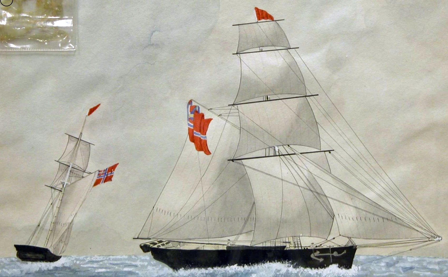
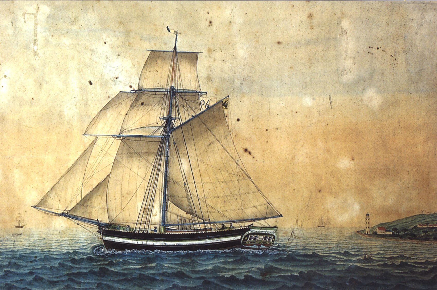
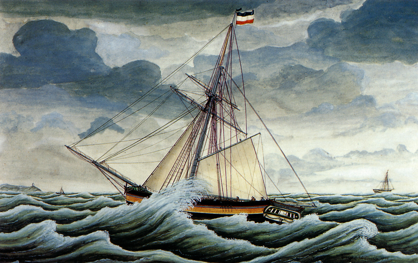
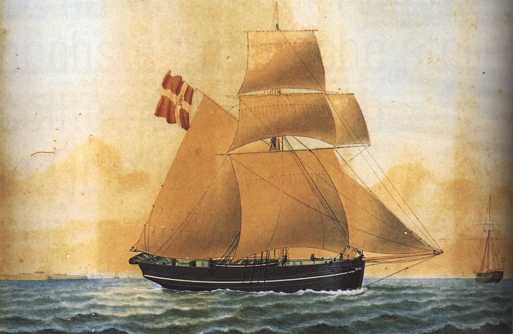
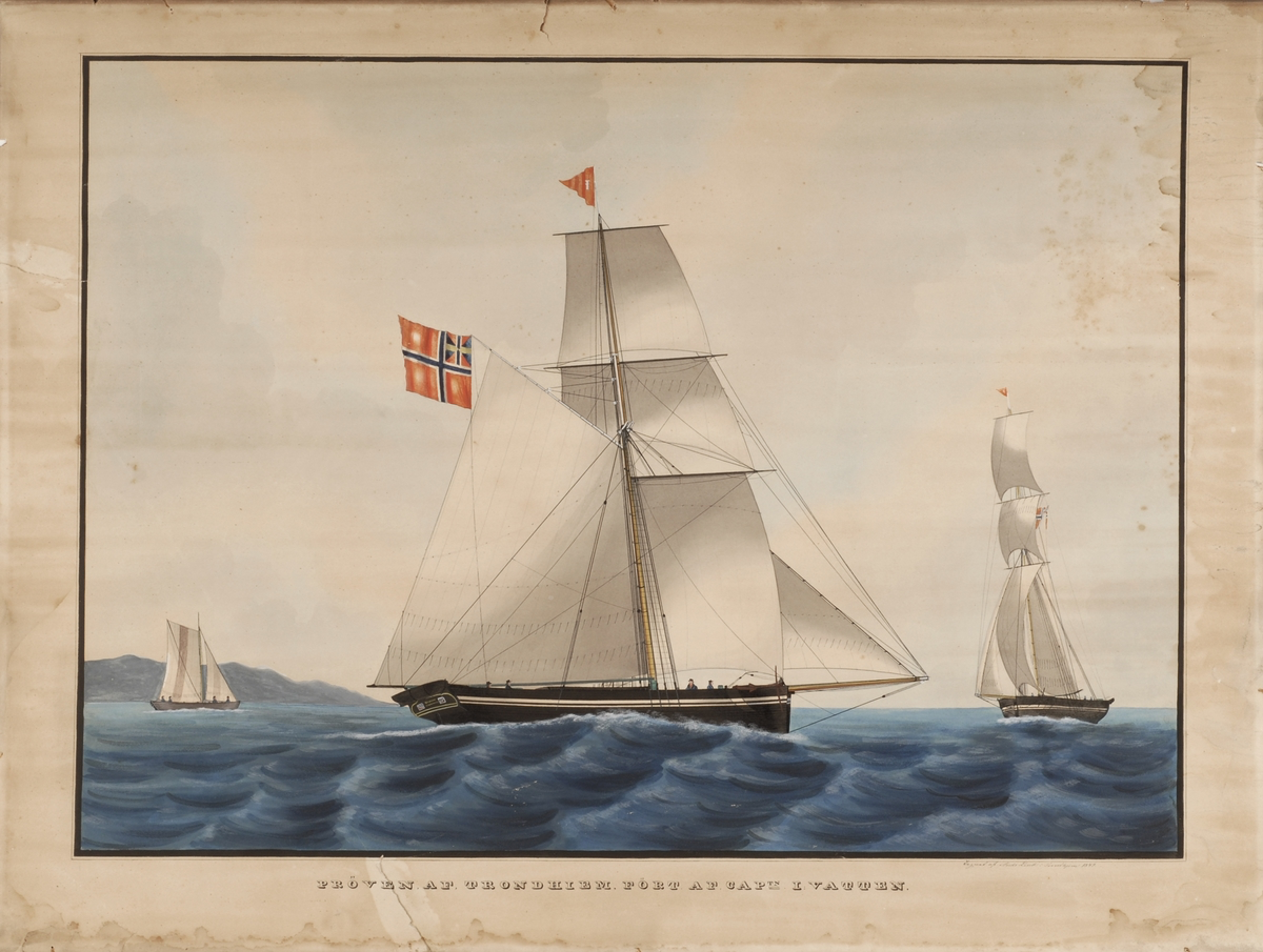
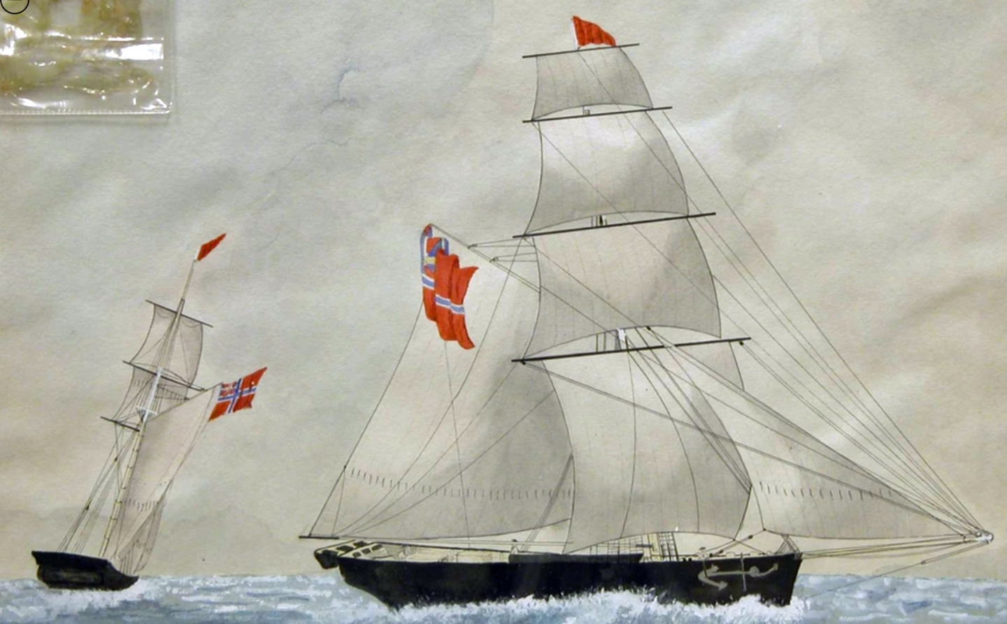
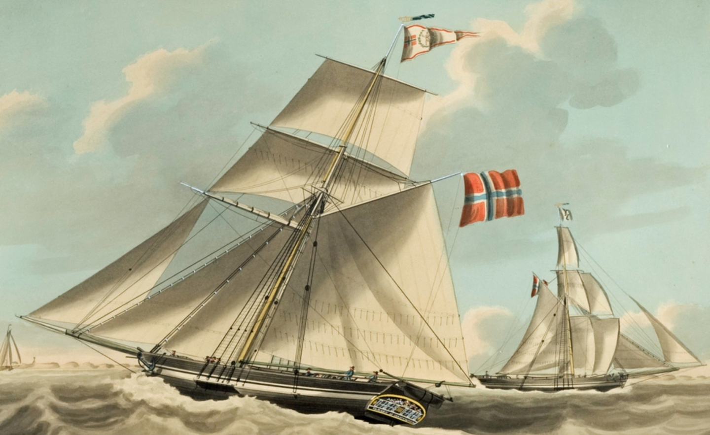
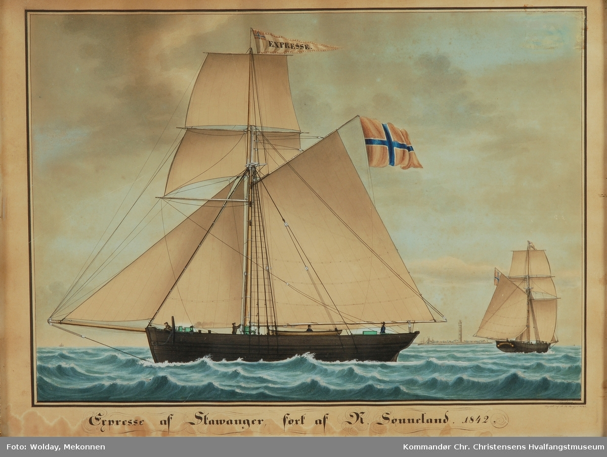
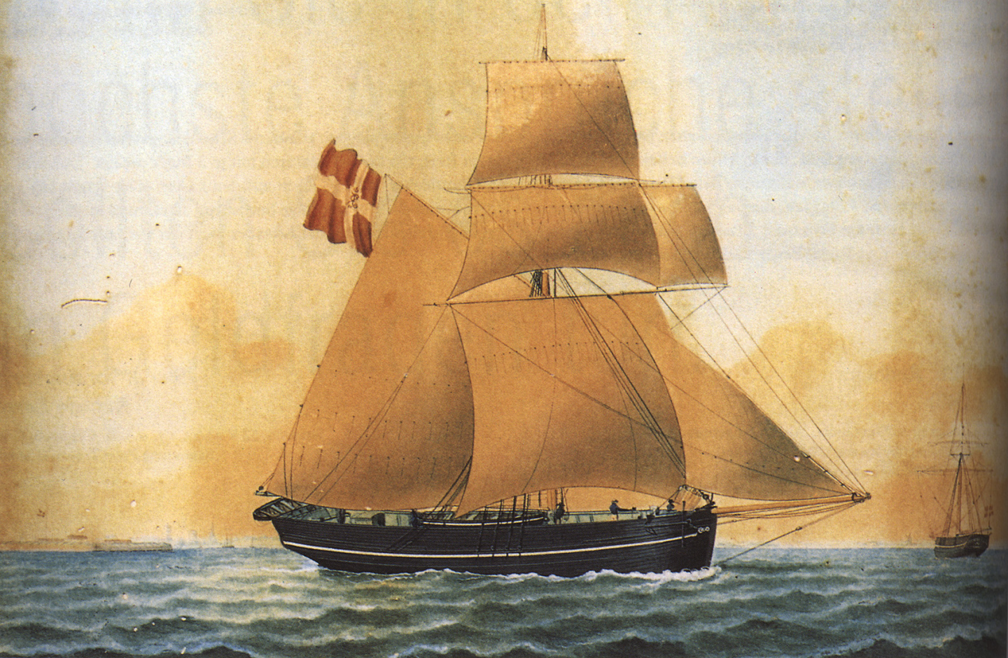
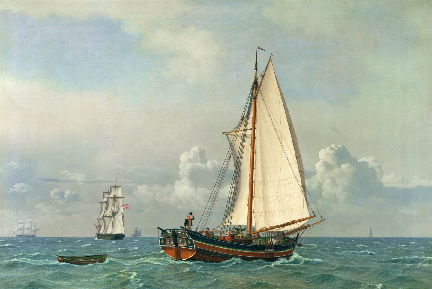
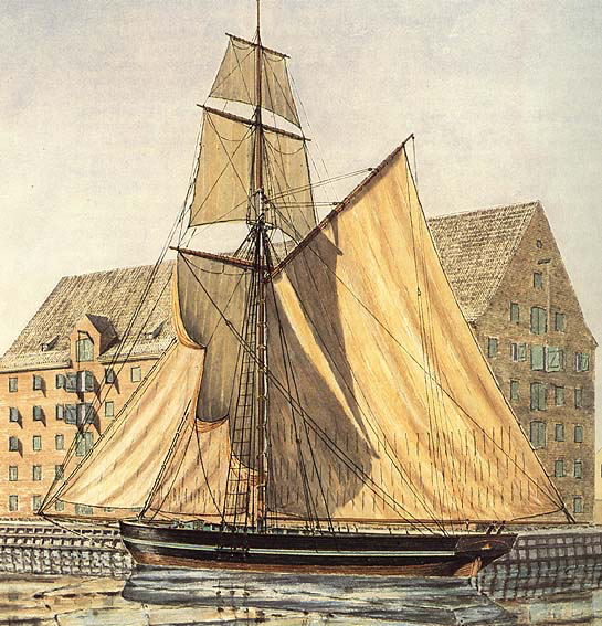
So, this is the beginning of a new adventure. Hopefully, the journey will not be quite as long, as for the previous project. This time, it is about 30 years older, mercantile and with sails: a so-called Pomeranian Rahschlup of around 1846, a somewhat anachronistic sailing vessel from the German Baltic coast. I have a certain attachment to this area which now is called Vorpommern, as part of my family came from this area and were also seafarers. Watercolours of a Rahschlup by Friis-Pedersen (in Friis-Pedersen, 1980, Handels- og Søfahrtsmuseets på Kronborg). Introduction Research on German small coastal trading craft and on this particular type of ship is rather difficult. All physical evidence has long gone, as have the men who built and sailed them. The German literature on commercial coastal craft from the Baltic Sea is quite scarce. Really the only books of some use are those written by Szymanski (1929,1934). He was able to travel much of the area post-WWI to inspect pictorial evidence and collect narrative recollections from people who witnessed the last few decades of commercial coastal sail. Some of his tracings of builders' plans he found at still extant shipyards and with private individuals are now in the Deutsche Technikmuseum Berlin (https://technikmuseum.berlin), but what has not been in public collections during WWII is now largely lost. The war and the lack of care and interest by builders’ and ship owners’ descendants have taken their toll. Surprisingly there were very few serious post-WWII maritime historians in both, Eastern and Western Germany, as well as in Poland, to which now most of now Pomerania belongs, who had an interest in commercial coastal craft. Most historian until today have mainly either an ethnological or an economic interest in the subject and typically very little background in and understanding of shipbuilding. To my knowledge there is no study on the complex interaction between economic and societal developments, resources available, and the technological development of the various coastal ship-building traditions in the 18th and 19th century. Wolfgang Rudolph is one of those exceptions, but he was more interested in the smaller artisanal craft. In more recent years Helmuth Olzsak measured and drew still extant boats around the Mecklenburg and Pomeranian coast (Olzsak, 2014), but he was neither a trained naval engineer nor historian. On the Scandinavian side, both the source availability and their modern evaluation is slightly better. Starting from a wide variety of Baltic craft, as illustrated for instance by af CHAPMAN (1768) for the middle of the 18th century, by the 2nd Quarter of the 19th two types craft seem to have dominated the group of single-masted vessels: the Jacht (or jagt in Danish) and the Schlup (or slup in Swedish and Norwegian). The Jacht was more prevalent west of Rostock, i.e. in western Mecklenburg and Schleswig-Holstein (as in Denmark), while the Schlup occurred more frequently in eastern Mecklenburg and, indeed, in Pomerania. The Jacht has two distinctive features, a very pronounced sheer (less so in Danish vessels) and a pole-mast, the top of which has a slight curvature forward. They had a flat, heart-shaped transom and carried their rudder outboard. The sail plan consisted of two foresails, a gaff mainsail with a square gaff-topsail. They usually could also set a large square foresail flying. These features were kept right to the end of wooden ship-building at the Baltic coast. A jagt (‘The Sea’) by C.W. Eckersberg, 1831, Louvre, Paris. The Schlup followed more the fashion of deep-water ship-building of the day. The mast always carried a top-mast. In the 19th century they were built with little or no sheer and had square or oval transom above the water, with a rudder inboard. The sailplan was similar to that of the Jacht, put the gaff mainsail was usually larger in proportion. She largely resembled those trading craft that would be called a smack in British waters. There was also one distinctive version of the Schlup that carried a single full mast. As the name in German indicates, the Rahschlup carried a heavier topmast with two topsails. This is a rather lofty rig for a humble sailing coaster, resembling the rig of the British naval cutters and the Swedish packets (CHAPMAN, 1768) of the late 18th and early 19th century. As their main area of occurrence was Pomerania, which belonged to Sweden from the days of the 30-Year-War until the Vienna Congress in 1815, they may be descendants of those Swedish packets that secured the connection between Stralsund and southern Sweden. Rahschlup JOHANNA of Copenhagen (1839), Tamm Collection, Hamburg Rahschlup of 1836, Schiffahrtsmuseum Rostock. Such rig required at half a dozen men or so to sail her safely. To the contrary, a Jacht could be handled comfortably by the master and a mate, or even only a boy (cf. Rudolph, 1958, on crewing). By the middle of the 19th century, such a rig appears rather anachronistic and would have been quite uneconomic. However, it would have had its advantages when working the coastal lagoons (Bodden, Haff) of Pomerania (now partly in Poland) and Eastern Prussia (now divided between Poland and the Russian Federation), as well as the coast of Southern Sweden. Dunes and rocks overgrown with shrubs and light woods would blanket near-surface breezes. DER JUNGE PRINZ (1819), painted 1832, Schiffahrtsmuseum Rostock Pictorial evidence from the middle of the 19th century shows a fairly uniform arrangement of loose-footed gaff mainsail (the gaff being considerably longer than the one on a Jacht, which would also be curved), a square gaff-topsail set flying on a light yard, and two (sometime a flying third one is seen) headsails. Like on the foremast of a topsail-schooner, there was a main yard below the trestle-tree and two light yards running on the topmast and spreading two topsails. A rather large square foresail could be bent to the main yard. In the earlier days a full complement of lee-sails may have been carried as shown on various ‘captain’s-paintings and one or two rare photographs from Norway, where this rig seems to have survived the longest. The mast was supported by three to four fully webbed shrouds and a couple of backstays set on tackles. The topmast was supported by shrouds to the trestle-trees only - apparently no backstays were used. The mast also had the usual complement of stays leading to the bowsprit and a fixed jibboom. Unlike to what was the fashion in deep-water sail during the 1840s, the masts of the Rahschlup had virtually no rake. Norvegian slup EXPRESSE (1842), Sandefjordmuseene. The Schlup ranged in length between 10 and 25 m with a width of as much as 7 m and a depth of up to 3.5 m according to Szymanski (1929, 1934). The Rahschlup naturally tended to be at the upper end of the range. She was always built carvel with a medium sharpness in the waterlines, a rising floor and usually some tumblehome. The entrance was rather bluff (certainly above the water), the run with some hollow. The sheer practically disappeared from the second quarter of the 19th century onward (as was indeed the fashion with larger seagoing vessels at that time). The stem was slightly curved or straight with only a little rake. The sternpost had considerable rake on top of which sat a gilling and it was crowned by a transom that became smaller over the time. The rudder ran inside and was nearly always worked with a tiller. Norvegian slup GLÆDEN (1836), Norsk Maritimt Museum, Oslo. Typically, the deck was flush, but could also have a raised quarterdeck, as was usually the case for the Jacht. There would have have been a small hatch before the mast and a larger one after the mast. Small companionways provided access to the crew's quarters between the small hatch and the spill and to the main cabin in the stern respectively. A small portable caboose lashed to the deck is often seen on paintings. The compass would live together with its lights in a housing with sliding doors lashed to the deck within convenient distance for the helmsman. Davits over the transom were provided for stowing the dinghy, which was, however, often towed. On some Schlups a larger boat was stowed was stowed in chocks on the main hatch behind the mast. Mechanical devices to make heavy work easier were, of course, an anchor spill in association with the post providing the footing of bowsprit and a cargo winch behind the mast. The anchor spill followed the technological development of the time from its simple form with an eight-sided trunk to the more sophisticated patent or pump-spills of the time. Also, the simple wooden pumps would make room to the more efficient cast-iron variety. Norvegian slup LOFOTEN (1841), Sverresborg Trøndelag Folkemuseum. Concerning the colour-scheme, Schlup would largely follow the fashion of contemporary deep-water sail (as opposed to the Jacht, which seems to have been more conservative). The colour scheme developed from scraped and oiled sides with black wales up to the early years of the 19th century to one with several strakes in different pale colours, such as pale blue, green or brown, and white, while the whale remained usually scraped and oiled. In later years the whole hull above the water was generally painted black with white rubbing strakes and sometimes the wale still scraped and oiled. Below the waterline coal-tar was sufficient in most cases, as these ships normally would not leave the Northern European waters. The inside of the bulwarks often were painted in pale green, pale blue or pale ochre before the middle of the 19thcentury, when white generally became the preference. Spars would have been either scraped and oiled in their entirety or would have tops and ends in a colour matching the rest of the ship, i.e. pale green, blue, ochre, or white. Norvegian slup PRØVEN (1847), Sverresborg Trøndelag Folkemuseum. Their trade As was mentioned earlier, their main area of operation was the Baltic Sea, with journeys round Skagen to harbours along the German, Dutch, Belgian, Norwegian and British North Sea coasts. Some may have traded as far as the Mediterranean (in which case they would have to be sheathed in copper or zinc), bringing back fruit and wine in exchange for e.g. wheat (Mecklenburg), hemp and pitch (Baltic states, Russia) or perhaps salted herring. Bricks (‘Flensborg stone’) and masonry blocks (from e.g. Bornholm, Gotland and Skane/Southern Sweden) might have also been commodities of interest for areas, where either the raw materials (clay) or the fuel (wood) to process them were lacking. Those registered in Schleswig or Holstein, however, would have carried the Danebrog until 1864 and could have traded freely to the Danish Westindies (https://en.wikipedia.org/wiki/Danish_West_Indies), now US Virgin Islands. To be continued


-
Perhaps you should also scrape off the moulding line on the lance …
-
One could have a decal printed with the blue lozenges pattern and then piece them in parts over a white base-coat. Otherwise, one needs to carefully layout the lozenge pattern in pencil over a white basecoat and then add the blue with a steady hand
-
Heat-setting white glue has been used by German modellers for decades ... I think there are two mechanisms working: the evaporation of the water as solvent and speeding up of the chemical reaction as such - according to van't Hoff every increase of 10 K in temperature doubles the speed of reaction.
-
I think I showed these pictures a couple of times before, but this is what I did in terms of painting and 'ageing': Basecoat: After washes of burnt umber and dusting with black, grey and white pastels:

-
The model railway guys (e.g. Woodland Scenics), sell little bag of ground up foam in different colours as foliage. I used this, dunked it into white glue and squeezed it onto the piling etc. as algal growth. It was dry-brushed a bit with a lighter green and then soaked in glossy acrylic varnish to give a wet effect: The model is in 1/60 scale, but it works in smaller scales as well.
-
In such cases I put a light dusting of white and grey pastel into the corners etc. Thinking about grimey places, there should be coal bunker for the donkey-boiler and in front of both there would be coal and ash grime. Also under the winding and steam machinery there would be a lot of oil grime.
-
I think on models of such vessels there can be never enough grime. I suppose the deck was never holy-stoned 😁
-
I think you emulate the old 'Builder's Model' or 'Boardroom Model' style very well with your projects 👍🏻
-
Quite spacious actually, so I wonder, why the toilet was set at angle?
-
It was unintentional, they used too fresh wood and put all the beams in the same way as they came from the trees, so that they all twisted the same - as far as I remember. Been there only once,