


wefalck
-
Posts
6,643 -
Joined
-
Last visited
Content Type
Profiles
Forums
Gallery
Events
Everything posted by wefalck
-
 Thank you to all of you for your kind wishes ! It seems that we have here in France a new subvariant of Omikron that is more contagious, with a shorter incubation period, but generally weaker, but symptoms of longer duration. The paradoxical situation is that the number of daily new cases is four to five times higher than at the beginning of 2021, when we went into full lock-down, but the government basically lifted all restrictions - masks are only required in public transport. Perhaps they think with 70% of the population vaccinated, they can manage the number of cases having to go into intensive care ...
 -
David, Canson is indeed a French manufacturer, who's traditions can be traced back into the 16th century and the Brothers Montgolfier were members of that family. The company offers a broad range of technical and fine arts papers. It seems that in Germany a heavily calandered and dyed in the material paper is sold under the denomination 'Canson-Paper', which is why I used this term. In my case it is their Iris® Vivaldi® with a weight of 120 g/m2, which is perfectly smooth on both sides. And: thanks for the kind comments !
-
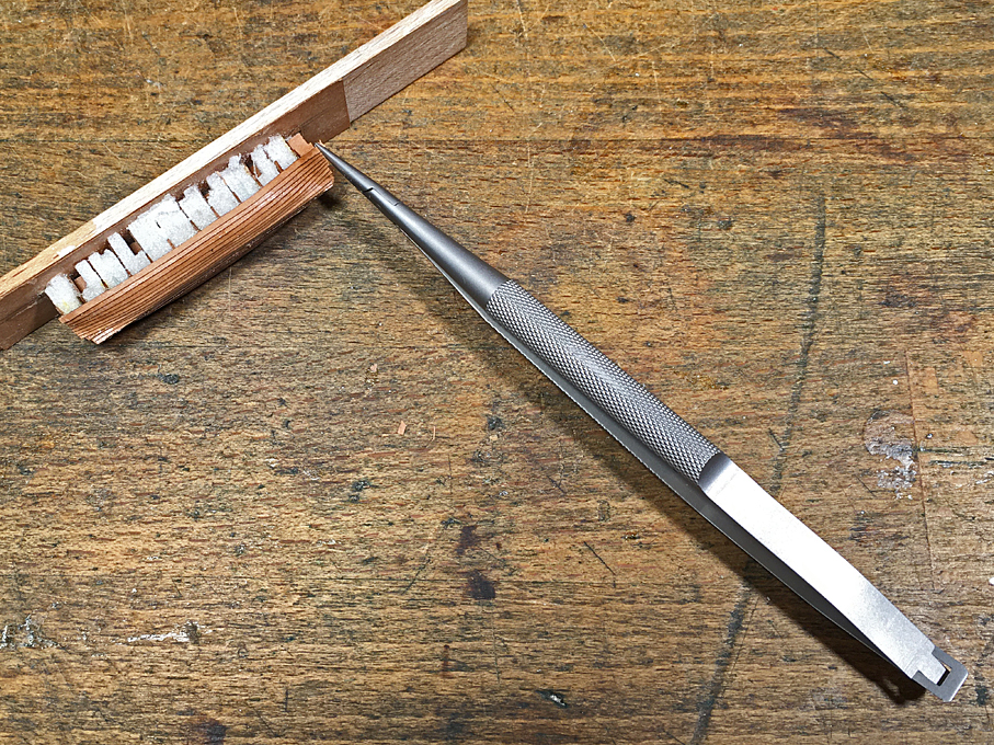
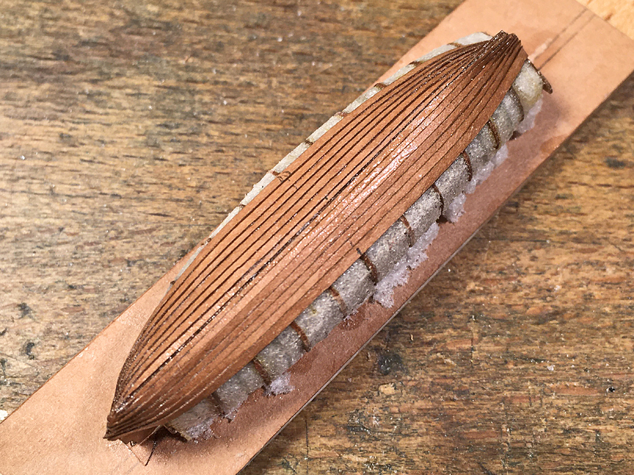
Work on the cutter stalled for a good two weeks due to an unexpected event: we went down to Spain to spend a week there and – in spite of all the precautions and safety-measures we took for the past two-and-a-half years and having been vaccinated three times, on the flight the virus caught up with me and my wife. Flu-symptoms with throat-ache, a light fever and general fatigue. We had to extend our stay by a week, until we tested negative. Still rather tired and bothered by a cough … at least we can relax a bit more for the next half year or so until the immunity declines again… ********************************************************************** Planking of the cutter continued … This work continued as before, eye-balling the run and spacing. I am not sure that I got the spacing at the bows quite right, as the planking is sweeping more up at the bows, than expected. As noted above, the forward section was more difficult than the rear section. Clamping the planks tight at the bows Once the planking was complete, the stem- and stern-post (or rather the deadwood) areas were cleaned up and sanded to match the stem- and keel-pieces. The planks were also sanded flush to the transom. Planking complete and cleaned up Planking complete and cleaned up The stem-keel-piece was laminated from three layers of laser-cut Canson-paper and lacquered into place on the boat. The outside contur was then cleaned up using a diamond nail-file. These files are very useful for the purpose. However, after a few strokes the freshly exposed paper has to be consolidated again with varnish to prevent it from fraying. Like the gig, the cutter had a rubbing strake running along the lower edge of the top strake. This was simulated again using a 0.2 mm copper-wire lacquered into place. Due to the charring from the laser-cutting process, it is difficult to see, whether there are any gaps between the stem-keel-piece and the boat as such. I probably will apply a thin coat of paint to be better able to see any imperfections, that then will be filled with putty. The completed cutter The completed cutter The completed cutter Overall, I a reasonably pleased how the cutter turned out so far and the strategy to attach stem-post and keel after planking is complete has paid off. To be continued ....
- 935 replies
-
- 23
-

-

-
I used silk fabric for model airplanes in the past, I think it was 14 g/m2. I put the stuff into a cardboard frame and worked/dried it horizontally, so no issues with not uniform paint distribution. While I don't sew sails anymore, this silk fabric sews better, when you back it up temporarily with some silkpaper - paper is less prone to be distorted when transported through a sewing machine.
-
The method with the ladies' stockings has been used successfully here by many modellers. So you should be on the right road.
-
tweezer reccomendation
wefalck replied to Boccherini's topic in Modeling tools and Workshop Equipment
Your best bet would be watchmaking or biology supply houses. Look out for brands, such as Dumont. Ideally, one should inspect them in person before buying to make sure you don't get 'seconds'. I pays off to pay a bit more initially. I had my main working pair of tweezers now for over 40 years, so worth the money. And don't drop it to the floor ... -
DEVICE TO FINISH ROPE ENDS TO HANG ON BITTS AND BELAY PINS
wefalck replied to Peter6172's topic in Masting, rigging and sails
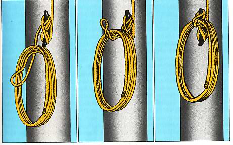
Yes, good idea. I improvised in the past. Just a side note: the coil would not be hung with the main loop over the belaying pins etc., but rather one uses the last bight and winds it around the coil so that one loop hangs out which is used to hang the coil. To cast loose, you just take it off the pin and pull on the running end - the loop sort of forms a slip-knot. It rather difficult to describe, but there are instructions on the Web: Or another method through which the coil can be cast loose even faster:
-
Nice find, thanks. This Major Meade was just one previous owner of the book. I own a set of 1894-1902 set of intruction books for torpedo-handling in the Austria-Hungarian Navy in which also one still finds a detailed description of spar-torpedos to be deployed from ships' steam-launches. At the moment I don't have access to my library, so I cannot check what tactical concepts they had in mind. In any case, they would not be effective against the capital warships of the time. One could think of attacking commercial craft or perhaps piers or lock-gates with little anti-torpedo craft defences - a task for which today you would employ underwater demolition teams.
-
True museum-quality ... I sincerly hope, it will end up at its intended place safely !
-
Knots and hitches are only used to temporarly fasten a line. In most cases eye-splices are used or seizings, when the rope would be too stiff to tie a knot or a splice would weaken it (as in the example above of the breech-rope). There are many specialised knots/hitches, but depending on the scale, they may be difficult to tie. In most cases I seem to get away with half- and clove-hitches, if required. A real splice would be a challange at most scales, but fake splices are easy to do. Personally, I prefer a fast-drying clear solvent-based varnish for securing rigging, as it can be easily softened with the solvent, if needed.
-
It works on my Safari 15.5 ... have to continue explore a bit more. Way back in December 1999 I was in Arlington for a conference and took the opportunity to visit a naval museum in the region. It seems that one was not allowed to take pictures. Otherwise there would be a record in my photographic diary (meticulously kept since 1972 ...). I have no other record of the museum, but my memory. However, I do not remember, which museum it was. It was accessible by public transport from Arlington, so much I remember. Anyone any idea?
-
Ahh, you should have popped into Gilberto Penzo's shop: http://www.veniceboats.com/ Some years ago, he published a book about the vaporetti: PENZO, G., Bocchin, A. (2004): Vaporetti - un secolo di trasporto pubblico nella laguna di Venezia.- 255 p., Venezia (Il Leggio Libreria Editrice). I do not own the book (not 'my' time), so I don't know, whether it contains plans. I did not find them quickly on his Web-site, but he used to offer plans separately on his site. Penzo also offers a laser-cut kit: http://www.veniceboats.com/Kit-vaporetto.htm
-
Valeriy, are the parts for the block hand-cut/-filed or photo-etched? The blocks look very good indeed. Judging by the matchstick, they must be about 3 mm long? I commend you for your perseverance in those dire circumstance! Keep fingers crossed!
-
To be honest, I don't like balsa too much, because it has a very directional grain and does not cut as well in small pieces. I have done some 30+ years ago a POB hull with bulheads in 0.25 mm brass, filled in with that stuff, which worked very well, because obviously the brass is so much more resistant to sanding than the Rohacell foam. The hull was some 35 cm long, so much easier to work with than a hull that is only just under 5 cm long. I did this at the time, because I wanted to have bulwark stanchion of the right thickness at the right position, which always a bit of a challenge on a flush-decked ship. The bulwark and other plating was made from 0.1 mm copper sheet to be able to simulate the rivetting. Yes, using slightly wider planks gave me more leeway to arrange the planking more uniformly. I see gig 2.0 coming up ...
-
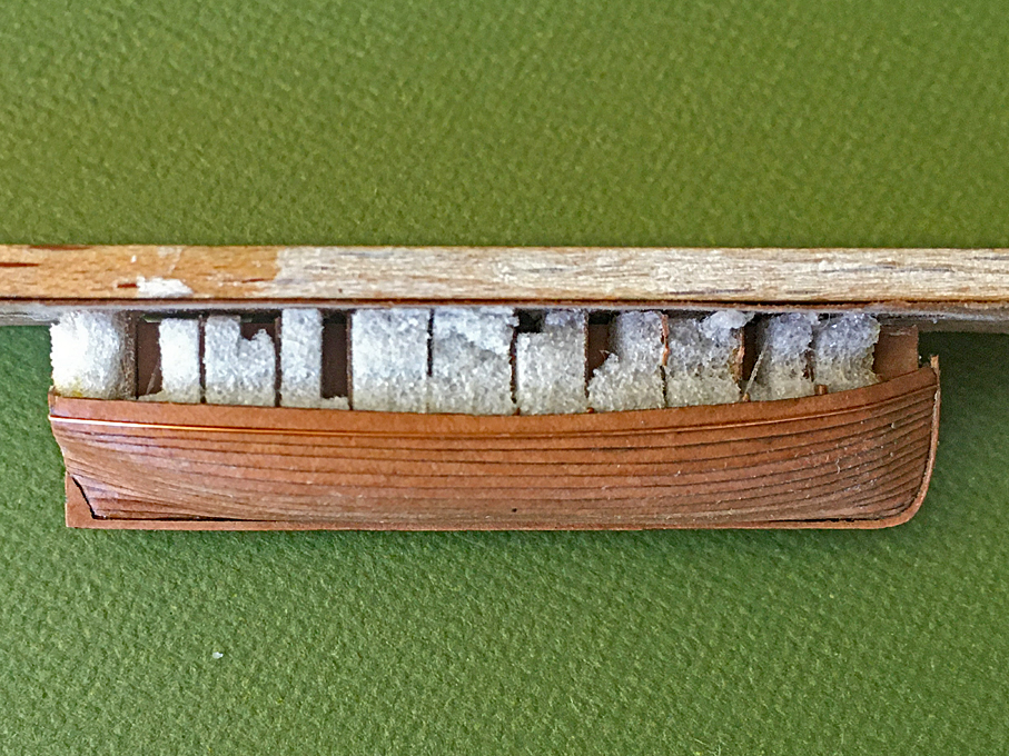
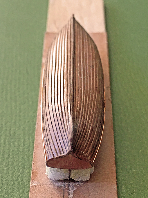
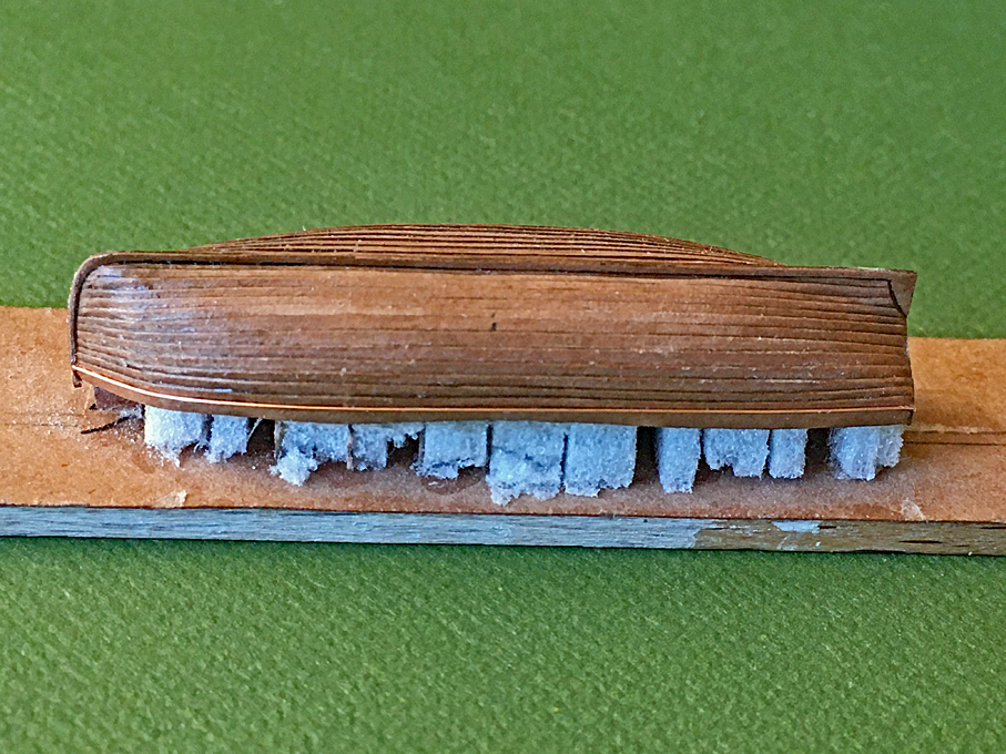
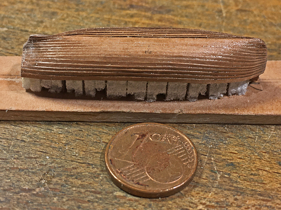
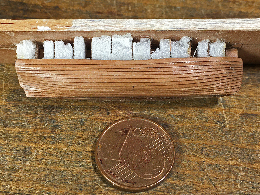
Thanks, Pat! On with The Cutters As noted above, I will be following a somewhat different construction for the cutters. I will not create a rabbet by gluing doublings onto the keel-piece, but will attach the outer stem and keel, once the planking is complete. Hopefully, this will allow a cleaner run of the planks into the stem. Also, all the planks will be cut with a straight line on one edge. Template for laser-cutting the keel-pieces and the stem-keel-combinations I also decided to fill in the space between the bulkheads to avoid the (minor) cave-in that occurred in some places of the gig. The material should be softer than the bulkheads and I choose a hard foam going by the name Rohacell, which is essentially foamed-up Plexiglas and of which I have still many off-cuts from a project some 35 years ago. Three strakes on However, nearly half-way now through the planking I have my doubts, whether there were any advantages in doing that. It turned out to be difficult to sand down the foam (which in itself sands very well with diamond abrasives or just sanding paper) to the bulkheads without damaging them and therefore alter the shape. If the infill actually is low, it become actually counterproductive, as the planks will follow this shape, rather than +/- the tangent between the bulkheads. Three strakes on The bow-section is not so easy to get right, as it is quite full and there is a tendency for the planking to rise too high, when it comes off the bottom with little dead-rise. Again, I did not mark out the division of the strakes, but eye-balled it. It would be quite difficult to do with sufficient precision at this size. Not sure how it will turn out. Planking half-way up To be continued ....
- 935 replies
-
- 15
-
-
I don't have a Dremel, but a 45+ years old primitive hand-held drill, the steel collets of which are of really good quality (like the PROXXON ones). It is used frequently for all sorts of grinding and polishing operations, less on wood, but more on metal. I am running it of a transformer with variable output and most importantly off a foot-switch (as all my power-tools), which gives you control without having to move the position of your hand on the tool. I also have one of those early PROXXON pen-size engraving tool, but I found the motor too weak, particularly when you reduce the speed to less dangerous (for the work-piece) values. My wife gave me for Christmas a cord-less (no-name) glass-engraving tool. While I like the idea of a cord-less machine as such, its speed-range is far too high and strangely enough you are at the highest speed setting, when you turn it on. Being cord-less it also cannot be controlled via a foot-switch of course - a sort of Bluetooth foot-switch would be a good idea actually. I keep quiet about it to my wife in order to not disappoint her, but I rarely use it. I gather she thought I could do some glass engraving, but that's not really my vocation. And I use these drills rarely for drilling ...
-
I cannot comment on its real usefulness, but I think it is still made. I saw it being offered on a Web-site not that long ago.
-
How was a ship's launch boat prepped to sail?
wefalck replied to Peanut6's topic in Masting, rigging and sails
BTW, in both, the Austrian-Hungarian and the German Imperial Navy, some boats carried a couple of large forks, looking like row-locks, with a stem long enough to clear the oars, in which the masts and sails were stowed, when not in use and being rowed. -
How was a ship's launch boat prepped to sail?
wefalck replied to Peanut6's topic in Masting, rigging and sails
It is always dangerous to back-extrapolate in time, but since at least the middle of the 19th century several navies published boat-handling instructions. I have, for instance, the copy of such a book for the Austro-Hungarian Navy of 1894. According to the above book, the boats were lowered with all the gear stowed in place. At this time it was not common anymore, to store boats in each other and most of the gear was kept inside the boats, when they were onboard. The larger boats were permanently kitted out with sails, water-barrels, bread-box, compass etc. The smaller boats were kitted out only for the intended operation. Basically the whole rig was stowed assembled and when needed the mast were stepped with all the gear attached. It was forbidden to go up in the masts, for any work on them they had to be lowered. Bowsprits were not used anymore at that time, so the whole rigging was inside the boat. -
Done that too, but I think we made it only down to Mustique, if I remember correctly.
-
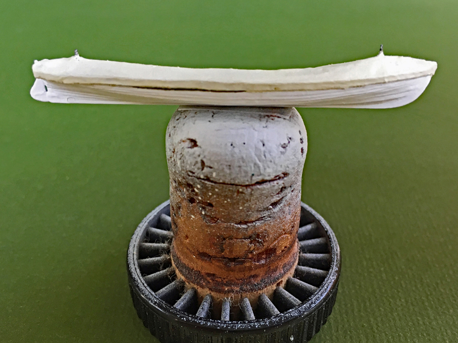
Thanks, gentlemen! Keith, the boat is 52 mm (2") long with an 11 mm (just under 1/2") beam. ************************************************************************ Painting the Gig The boat was given a few thin coats of white acrylics (Vallejo) all over with the airbrush - the results of which was quite sobering: all the imperfections that were not quite visible in the ‘raw’ state now began to stick out. The jagged edges from the laser cutting that seemed to disappear under the varnish are no rather visible. Also, using toilet-paper as the basis for the boat-cover was not a good choice. I used it in military-modelling in my youth to simulate tarpaulins, but perhaps then my standards were lower. I choose it, because I wanted something that looks limp and more casually draped, as can be seen on many photographs of the time. However, it turned out to be fuzzy on the surface and the edges in spite of being soaked in sanding filler. On the next boats I will try some Japanese silk-paper that I bought some time ago. I hope when it is wetted it will drape well. The completed gig on an ordinary port-wine cork I then brush-painted the boat-cover in thick white acrylic with tiny drop of Vallejo 71.288 (Portland Stone) mixed to it. This gives a very light off-white colour. I don’t actually know, whether these boat covers were oiled or painted canvass. According to the painting regulations for boats, the top two strakes where to be painted black. Due to the cover not much of them is visible, but I managed to tatter on a bit of black here in there. The completed gig on an ordinary port-wine cork I will now turn my attention to the other boats, considering the experience with this one. If they turn out better, I might try a gig 2.0. To be continued ....
-
Kevin, using black acrylics to fill the seams did not work for me. They are just drying too fast to be wiped off easily. I know that some people used oils for the purpose, but that makes it difficult for the following acrylic washes and the final varnish, as the oils are water repellent. I would rather use some black ink. If you have one of those old-style drafting pens, where you can adjust the line-widths, this might be useful for applying the ink. From the gloss varnish it should wipe off quite well, but may still leave a bit of 'haze' - I found that this doesn't do any harm. It would depend on the pride the master takes in his ship, but clippers in general were well-maintained (the premium freight rates paid for this) and so the decks may have been holy-stoned from time to time, navy fashion. I think I would go for a very light yellowish-reddish tint.
-
Going around at night in a dinghy, one can also have strange encounters: we were motoring back out to the boat in a moon-lit night in the usual condition of constrained perception, when suddenly there was a big splash. We first thought that we hit something, but when we switched on the torch, we saw a baby barracuda flapping on the floor of the dinghy. It had jumped out of the water and landed in the dinghy.

