


wefalck
-
Posts
6,652 -
Joined
-
Last visited
Content Type
Profiles
Forums
Gallery
Events
Everything posted by wefalck
-
 This little ships got very crowded in places, particularly on the foredeck and one wonders how they managed to work them.
 -
Of course, I didn't scroll back through the posts. I hope a good year later the hand is on the mend!
-
Experience shows, that in the modelling realm, these values are not so important. You will get a feeling for what works. It is different in the professional world, where efficiency is money.
-
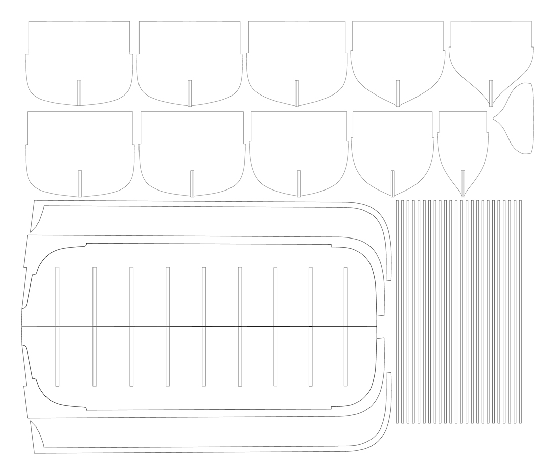
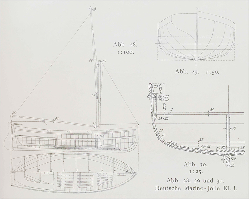
The shipyard has been on a somewhat extended summer-shutdown, including the drawing-office (which was not quite planned so, but the heat at my abode in Spain, just made me not feel like working too much on the computer …). Thank you very much for all the likes and encouragement that has been accumulating since the last update! ***************** The Jolly-Boat Rather than doing the second cutter, I am now tackling the jolly-boat. This is the smallest boat of the complement, at 6 m (= 19’8”). I am in for challenge, as I plan to build this open and fully equipped, ready to be lowered in case of man-over-board or a similar emergency. I did not find an earlier drawing, but the drawing in the 1911 issue of the ‘BRIX’ is quite detailed, although it is for the karweel-planked version, while I will kit out WESPE all with clinker-built boats. It appears that the frames are drawn to the inside of the planking, which is exactly what I need. The arrangements for the keel and stem-/stern-post will be somewhat different from what I did for the other boats, as the bulkheads will only act as formers. Drawing of Class 1 jolly-boat from Brix (1911) The laser-cut framework will be infilled with hard foam (Rohacell™) as before and then covered in cling-film to prevent the frames etc. from sticking to it. Below is the laser-cutting template for the main structural components. The thin strips on the right will become the ‘bent-in’ frames. Other parts will be drawn to fit as I am going along. Laser-cutting templates for the formers and main structural components of the jolly-boat. I will also need to still draw a base-board for the construction process, that has notches for the upper ends of the frames to rest in. To be continued ....
- 935 replies
-
- 11
-

-
Ras, sorry can't help you there with any substance. Looking through my list of literature, I found a couple of references that might be helpful: Anonym (1914): Nautical Terms - Motor Boats - Marine Gasoline Engines - Management of Marine Gasoline Engines - Motor-Boat Navigation - Motor-Boat Rules and Signals.- p., Scranton (International Textbook Company). - available as eBook, but I don't have the link anymore. OVERTON, G.L. [Ed.] (1926): Catalogue of the Collection in the Science Museum. Water Transport. VI. Marine Engines & VII. Marine Boilers.- ? p., London (H.M. Stationary Office). - I don't have a copy of this catalgoue, but you could have a look at the on-line resources the Science Museum in London now offers: https://collection.sciencemuseumgroup.org.uk/search/objects/categories/marine-engines?page[number]=1 I have also a few books on early German boat-motors, but this is likely not to be very helpful here. The (practical) pioneers for IC motors in boats were first the Danes and then the Dutch and Germans, I believe.
-
Small diameter gears
wefalck replied to bridgman's topic in Metal Work, Soldering and Metal Fittings
I found the clock- or watch-wheels are too thin and their teeth normally are too deep to represent such gears satisfactorily. Try to work out the number of teeth on the respective wheels by counting e.g. a quarter of the circumference, or whatever is visible. You then can try to find on-line some (old) engineering textbooks that give you an idea of the relative proportions of the teeth. On this basis you can draw on the computer an enlarged image of the gear (it's a lot simpler and precise to draw at 20:1 or 10:1 scale than at the original 1:50 scale). The print it out at the right size and stick two carefully aligned copies onto each side of the material that you are going to use. No you can use files or even a skalpel to shape the teeth. If on the model you won't be able to see parts of the gear, you don't really need to shape the teeth and save yourself time. Make sure that for meshing gears you draw the same 'modulus' or 'diametral pitch' (check on Wikipedia what this means). Of course, such gears probably wouldn't really work, but they can be a good representation - better than clock- or watch-wheels. -
How metal hooks are stropped onto block
wefalck replied to glennb17's topic in Metal Work, Soldering and Metal Fittings
In any case, in real practice it would not be possible to wrought the ring closed with the rope through (with or without thimble) - the heat would burn your rope. The same applies, when bending the hooks from wire and (silver-)soldering the ring closed. One has to follow full-size practice and splice the becket after leading it through the ring. In small scales, one may need to fake the splice and hide the joint under the seizing. -
In principle, fillers are a good idea, particularly, when bulkheads are thin and spaced wide apart. The need for them also depends on how thick the planking will be - thin planks tend to kink much more than thicker ones, of course. In your particular case, however, I have the feeling that fillers might not really be needed, as your bulkheads are quite thick and closely spaced. The wood used for the fillers should be about the same hardness as the bulkheads, if it is too soft, you might sand hollows into them between the bulkheads, if it is too hard, it is a lot of work to shape them. Looking at your model, I have the feeling that you might want to define the rabbet line better. It looks, as if you won't have much space for the planking above the bulkheads in the midship section. But then I don't know, how you will construct the keel.
-
Another project that I missed until today ... although I would be mentally/historically on the other side of the fence
-
Keep it coming !
-
How could I possibly have missed this new project since May! A (a non-selfpropelled) derrick lighter after some 1880s plans has been on my projects list for decades ... looking forward to see your solutions for the derrick and the machinery.
-
Jon, I did not do any systematic research on this, so some of my observations are rather conjectural: The layout of European and North-American vessesl around the middle to late 19th century was quite different. In virtually all cases the crew-quarters in Europe were forward (with all the inconveniences described quite graphically by Dana in his book). The kitchen, fuel storage and storage of other combustible materials, such as lamp-oil and paint, where in a 'caboose' (with the original meaning of word), that is a mobile deckhouse that was tied down with iron rods. Accomodation for the captain/skipper/owner and perhaps the mate was in the rear. Sometimes it also housed the skippers family, at least the wife and below-school-age children. To provide more head-room from around the 1850s on the rear deck was raised as a poop. To the contrary, in America a larger deckhouse was constructed that accomodated the whole crew and in a forward compartment the kitchen. This could have been an autochtonous development in America to provide a more healthy living space, but could have been also a tradition that was brought across the pond by Scandinavian shipbuilders/mariners. As an exception to the above discussed European layout, Scandinavian lumber-traders seem to have had larger deckhouses. The reason was that they needed to have bow-ports in order to be able to stow long pieces of timber and the crew accomodation forward would have been in the way. By the same logic, moving the skipper's quarters onto the deck gave more room for long timber. I would doubt that 'hot berthing' was used on these traders, it was more common on certain naval ships. If you calculate say a 7' headroom in the deckhouse, this would allow you to have three bunks above each other plus a storage space for the seamen's chest under the lowest bunk. Thus in a 15' long deckhouse you could sleep 12 crew. You would need around 4' to 5' between the sides of deckhouse and the bulwark to work the sails etc. BTW, I was wondering about the rather tall 'skylight' on your deckhouse that made it look a bit like a 'caboose' (in North-american railway sense). If there was a skylight at all, I would have thought it be rather low in order to clear the main-boom, which you want to have as low as possible in order to bring the meta-centre of the sailplan down. When estimating crew numbers, I would think that four men per mast would be sufficient, but it depends on the size of the square sails that need to be handled. In Europe smack-type ships were sailed with three hands, including the skipper and a boy, while schooners may have had six hands and small brigs perhaps eight - which is why many brigs were converted to brigantines, which saved a quarter of the staff-cost and the cost of maintaing the square-rig gear of the main-mast without loosing much of the sailing capacity.
-
I am not an expert on kits, but it seems that the laser-cut kit by Master Korable are setting standards as far as the precision and ease of building is concerned, judging by the various building logs here and on other fora. They apparently also require a minimum set of tools only. I cannot speak from experience, as I grew into this hobby since my childhood, but it may be advisable, when diving into the deepe end, to takle a boat-kit first, rather than a ship-kit as ones mentioned in your post. Ships are quite complex 'beings' and it is easy, even with a good kit, to get lost, when you don't have a good feeling for how a ship is actually constructed. And once you get lost, you may become frustrated and give up, which would be a pity. Also, one should not underestimate the challenge of rigging and you may actually spend more time on it than on building the hull (particularly with laser-cut kits) - there are very few short-cuts for rigging-job well-done.
-
Stay away from cyanoacrylates for coppering, as it tends to stain the copper. A solvent-based contact cement is the best option.
-
For an European eye these American deckhouses have a strange appearance, like a log-cabin that has floated onto the aft-deck during a storm 😏
-
Veggies are for softies and women ... and they were expensive. The fishing trips would have lasted only a day or two, depending on success and weather conditions.
-
Probably not ... they ate boiled potatoes on those boats - a chip-pan would have been far too dangerous (it is the major domestic fire hazards in British houses to have a pan with boiling oil on a gas cooker 😱). I think it was an anecdote recounted by Wolfgang Rudolph in one of his books on the boats from the Pommeranian coast: A guy was taking a passage on a fishing boat (probably late 19th century) and the fisherman offered him a meal during the trip. As the guy did not come from the coast, he tried to be modest and ate mainly from the potatoes - whereupon the fisherman reprimanded him: "Mate eat fish, potatoes are expensive!". The kitchen utensils on these boats typically consisted of a frying pan (for the fish and perhaps some bacon), a pot for boiling potatoes, and a kettle to boil water for coffee.
-
I think on many double-hulled boats they use(d) either wooden or iron connecting rods between tillers. The connecting rod would need to transmit largely only pulling forces, it could be quite thin in order to have a strength comparable to that of the tiller ropes.
-
Exemplary attention to and rendering of the details - as always ! I think she has the pontential to become one of the most detailed models of such yachts ever built ...
-
This is another recurrent discussion ... as Allan said, if you require high accuracy and long useability, then you might to go to either an industrial supplier or a watchmaker supply house. However, there you will have to pay a bit more. I am not sure about that, but I would suspect that hobby suppliers can only maintain their prices by buying lower quality or 'seconds', i.e. drills from reputed manufacturers that did not meet their internal quality requirements or that of their customers. Grinding sub-millitmetre drills is quite a challenge and may result in quite a lot of 'seconds'. In general, they are ground from calibrated 'drill-rod', so that the shank is the nominal diameter. It is here where diameter should be measured. In fact, such drills may cut slightly oversize holes, because the cutting edges may not be exactly centred. The most exact drills with respect to running true are those with thickened shaft. They are made with 1 mm, 1.5 mm, 3 mm and 3.2 mm (= 1/8") shaft. If you are drilling by hand, you are quite certain to end up with an oversize hole. Nominal diametre holes in the sub-millimetre rand can really only be achieved with a pillar-drill or similar and collets (chucks normally have to too much run-out). So at the bottom line, I would not worry too much about the drills not being exactly the nominal size. Pick a drill that matches the material for which you are drillng the hole for.
-
Also, this is discussion that has resurfaced several times over the past few years. I gather, in these discussions we quite exhaustively covered the different options and materials. So, it will be worthwhile to plough through theses threads.
-
WWII Sunken German Warships Exposed by Drought
wefalck replied to mtaylor's topic in Nautical/Naval History
I believe the scuttled ships in Scapa Flow are not only protected was a war memorial, but expressedly as a valuable resource for low-background radiation steel.

