


wefalck
-
Posts
6,643 -
Joined
-
Last visited
Content Type
Profiles
Forums
Gallery
Events
Everything posted by wefalck
-
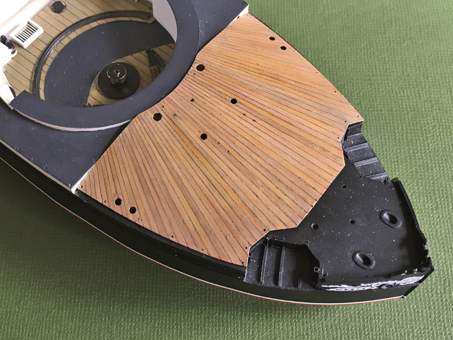
 You need to work with very dilute washes, to the point that you barely see any paint on the brush, and to apply this to planks selectively to get a random pattern, but not too different. Opt rather for lighter shades. In my case I assumed the deck was teak, but you would have to check, whether CUTTY SARK's decks were teak or pine, I don't remember. Compare also photographs before and after the fire. And yes, a wash with burnt umber or other dark brown can bring out nicely the surface texture, but you don't necessarily want this on a well-maintained clipper-deck. At the very end I sealed everything with gloss(!) varnish and redrew the engraved plank seams with a 0.1 mm thick permanent marker. One could also use a pen and ink, I suppose. I wiped off any excess immediately, so that only the engraved lines were filled with ink - that's the reason for the gloss varnish, then the ink does not get into the surface roughness of the acrylic paint. Finally, I spayed the deck again with flat varnish and applied a very dilute white/off-white wash to tie everything visually together. The very last step was to spray on some flat varnish - such decks are basically flat and not satin. Quite a bit of work, but I think it pays off.
 -
Reminds me of our trips to the Carribean, e.g. the BVI and USVI. Took the dinghy to on-shore bars and restaurants and after some drinks (the bartenders took a 1 pint plastic beaker and went up and down the shelves until it was 3/4 full - the rest was topped up with orange juice - a concoction called 'Force 12') we had to find our anchored boat in the dark. They all look the same, the hired boats. Eventually, we tied some towels to the rail, to look a bit more distinct ...
-
Kevin, why do you want to get surface texture on a wooden deck? At 1:96 scale plastic models one usually has to work hard to get rid of the misguided 'wood' texture molded in. Wooden decks are normally kept very smooth. The example below is in 1:160 scale, the bakelite-paper deck was lightly engraved with the plank seams and thent he wood character was achieved by giving each plank a slightly different colour, imitating the natural variability of wood. The piece was given a base-coat of Vallejo Model Air 71075 ‘sand (ivory)’ using the airbrush. In a next step single planks were randomly given a light wash with Prince August 834 ‘natural wood transparent’ or Vallejo Model Air 71023 ‘hemp’ (which turned out to be a bit too dark actually). In a next step randomly selected planks, particularly those ‘hemp’ ones were given a very light wash with Vallejo Model Air 71288 ‘Portland stone’. Another very light wash with Vallejo Model Air 71041 ‘armour brown’, toned down with yet another very light wash using Vallejo Model Air 71132 ‘aged white’, pulled everything together.
-
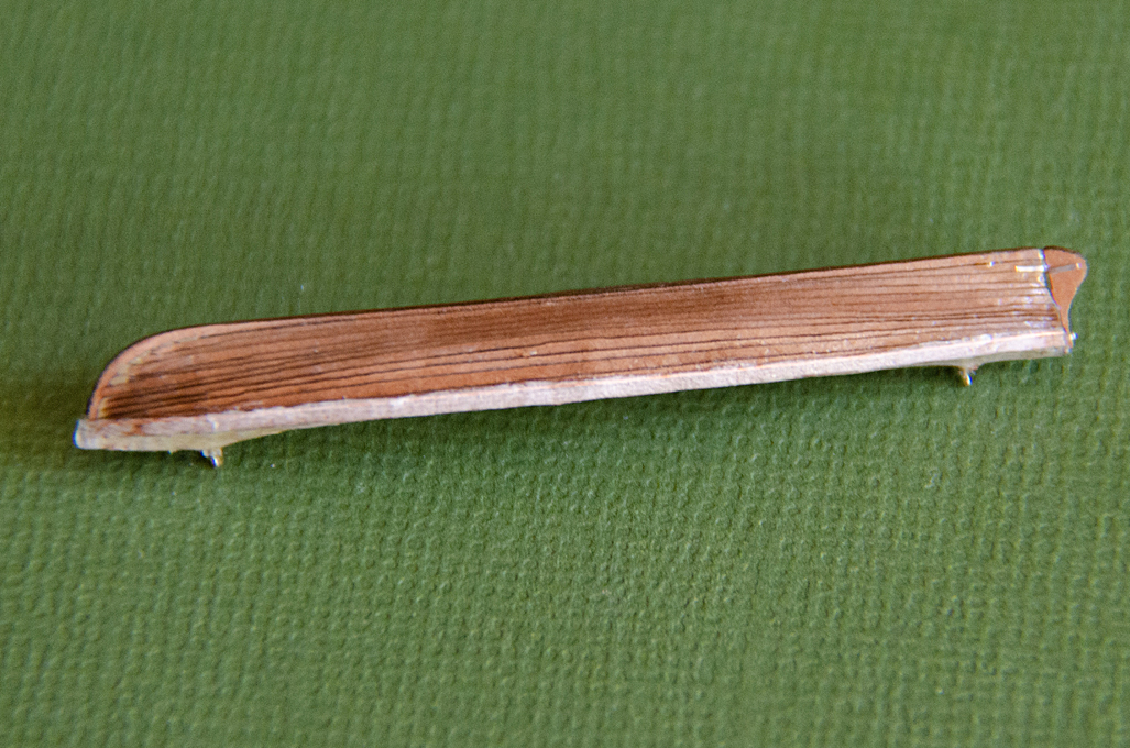
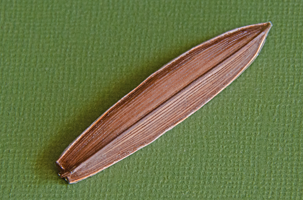
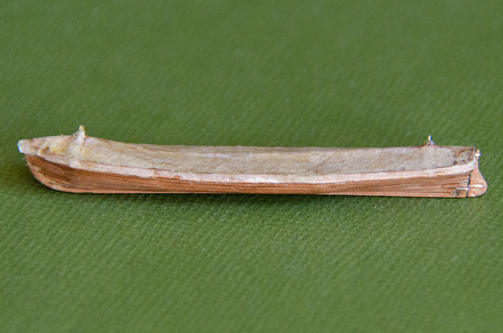
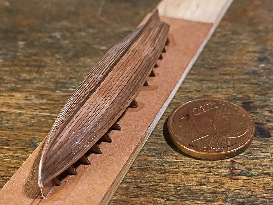
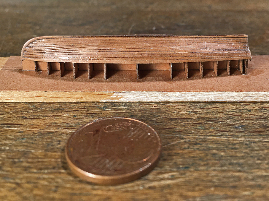
Thank you, I keep trying ... ******************************** Work on the Gig continued The planking progressed reasonably well, but I actually needed to more strakes per side to be able to go up to the sheer-line. Not good for strake counters … I attribute this to the wider overlap needed than expected. This was particularly the case, where there is a significant angle between planks, e.g. at the turn of the bilge. For the other boats, I will have to cut the planks a bit wider. Planking completed A few conclusions from this exercise for the other boats: - Cut the planks tapered only on one side, as they can edge-bend, when soaked in varnish - Cut the planks for 30 to 40% overlap not 20% as done in this example; this gives more flexibility to adjust the planks - Do not try to imitate full-scale practice by running the planks into a rabbet on the stem, rather attach the outer stem and keel-piece after the planking is complete and has been trimmed down to the rabbet line. Planking completed The planking now was cleaned up and the excess at the transom trimmed back. I tried to sand the jaggy edges a bit, but that did not work very well on the paper. However, in the varnished state it is not very visible. One has to see, when it is painted. The hull was lightly rubbed down with fine steel wool to smooth the surface. Then some spots, where touched up with some putty. Rubbing strake from 0.2 mm copper-wire installed According to the prototype cross-section, there was a rubbing strake added to the top-strake. It was ‘faked’ by attaching a 0.2. copper-wire below the last strake. Now the boat was ready to be cut from the base. The bulkheads were cut down and the keel-piece trimmed to a line that would be followed by the tarpaulin cover. There is a hoisting chain fore and aft to which the falls of the boat-davits will be hooked, As only the rop ring will be protruding from the boat-cover, this chain was simulated by a drilled together piece of tinned 0.2 mm coper-wire. It was hooked into a bulkhead and glued down with varnish. Boat cut free from the building base Most modellers seem to show the boats open, but most historical photographs show them covered. The design of the cover seems to vary a bit and I could not find information about this. Some photographs show the cover going down over half of the sides of the boat, with ropes apparently zig-zagging down to the keel and back up on the other side. Others seem to show a line going through a hollow seam to pull it tight around the boat. I opted for the latter to show more of the planking and the (later) paintwork. Gig with simulated cover I was debating with myself, whether I should first paint the hull and then add the cover, or the other way around. I opted for the second, as messing around with varnish, could damage the paintwork, even though it made it more difficult to hold the boat during (spray-)painting. Basis for the cover was a piece of ironed-flat toilet-paper that was draped over the hull and then soaked in varnish resp. sanding filler. It was smoothed down over the edges and down to the rubbing strake. Once dry the paper was cut back to the rubbing-strake with a new scalpel-blade. Underside of the gig showing planking I almost forgot the rudder, that seems to have been kept shipped, when the boats were suspended in the davits. It was drawn on the basis of BRIX (1883) and laser-cut to be laminated from two layers. The pintels turned out to be far too small to reproduced, but the respective bands were simulated by flattened, tinned copper-wire. Gig with rudder shipped The gig is now ready to be painted. To be continued ....
- 935 replies
-
- 21
-

-

-
HMCSS Victoria 1855 by BANYAN - 1:72
wefalck replied to BANYAN's topic in - Build logs for subjects built 1851 - 1900
While I was talking ... one member there made me aware of this offer: https://timesavers.com/search.html?q=drills&go=Search Not sure whether and at what price they would deliver to Australia.- 1,013 replies
-
- 2
-
-
- gun dispatch vessel
- victoria
- (and 2 more)
-
HMCSS Victoria 1855 by BANYAN - 1:72
wefalck replied to BANYAN's topic in - Build logs for subjects built 1851 - 1900
Pat, I posted an enquiry a week ago or so on a watchmaking forum about sources for spade-drill 'down-under', but unfortunaly no useful replies came forward. Sorry. Probably, that forum has mainly members from the USA and Europe.- 1,013 replies
-
- 2
-
-
- gun dispatch vessel
- victoria
- (and 2 more)
-
Do you really want to spoil your model with sewn sails ? I would think twice about this, because they never look right. I would rather go for something like silk-span (Japanseide), glue and paint. There are various examples for such sails her on the forum. They look much more to scale.
- 180 replies
-
- 2
-
-
- pilot boat
- Elbe 5
- (and 3 more)
-
Not 'my' time and my preferred aesthetics, but very impressive rendering 👏
- 2,699 replies
-
- 6
-
-
- heller
- soleil royal
- (and 9 more)
-
Thanks, gentlemen ! Phil, this is exactly what I am going to do for the other boats. The original idea was to curve both sides, because I was not sure how well the 'planks' would bend across the wide side. However, once soaked in varnish, they can coerced into shape quite nicely without buckling. This is a learning process. Some 25 years ago I built a small clinker-dinghy in 1:60 scale like this over a wooden former with thin bent frames and planks from bakelite paper. I had the benefit of a plank layout, as I used the paper-model in Eric McKee's brochure on clinker-building as a basis. The bakelite paper can be sanded over the edges and feathered out for the plank above with a engraving chisel. That worked very well.
-
Ketih, I am using a really cheapo laser-cutter. The input are b/w JPEGs, which are converted to pixels and when it finds a black pixel - zap! This conversion and perhaps the mechanical resolution of the stepper-motors limit the efective resolution to 0.1 mm. This means that the 'planks' are only about 7 pixels wide at their widest part, tapering down to about 3 pixels at the ends over a distance of 200 pixels - so steps are programmed in
-
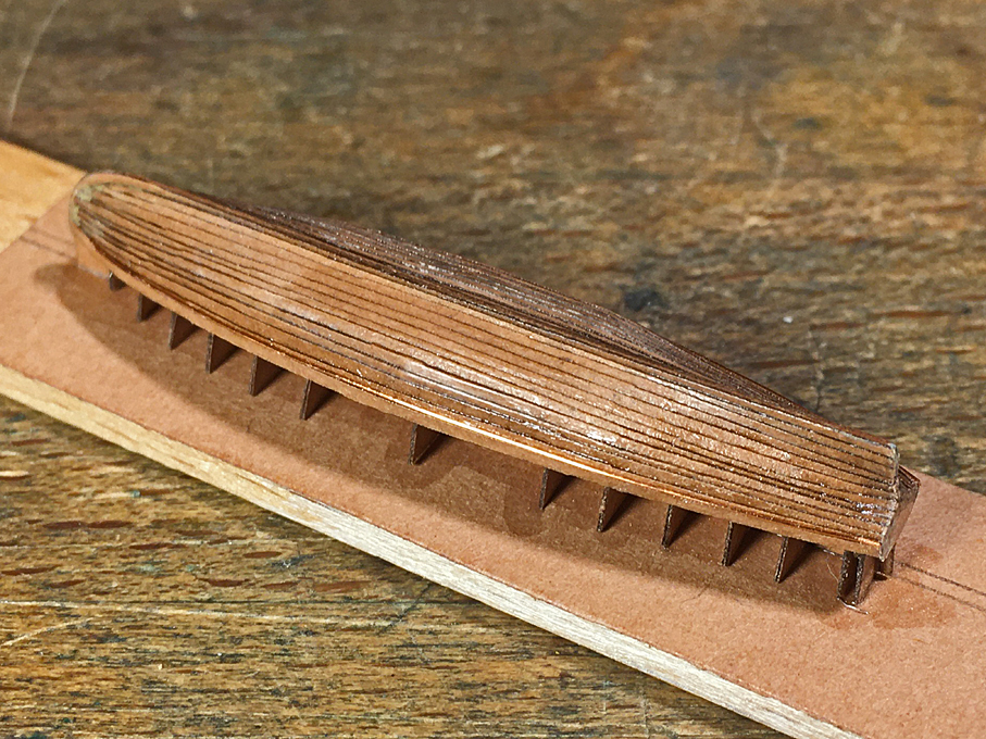
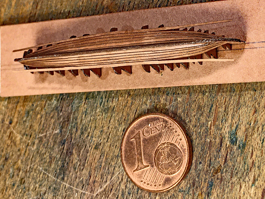
Thanks, gentlemen, for the encouragement - much needed Pat, the gig will be represented cover, so no need to worry about the internal structure. There will be only one small boat shown uncovered and I have to think about that construction. I first have to check, whether for this bent or sawn frames were used. ***************** Planking the Gig Just a little update on my efforts to plank the gig. The framework was fixed to a piece of wood to keep in shape and for ease of handling. The ‘planks’ were laser-cut from Canson-paper as indicated earlier. Unfortunately, I do not have a software (yet) to develop a planking layout, so the planks were tapered, but straight and all of the same size. However, when wetted with varnish, the paper, unlike wood, can be relatively easily bent and shaped across the wide side of the plank. Planking in progress When laser-cutting the planks, I ran into a small glitch, that is the outside of the planks have such a shallow curve, that the ‘stepping’ due to the 0.1 mm resolution of the cutter becomes quite pronounced. I hope I can remove this later by sanding. When fitting the planks, I found the best way was to fix them in the middle first and then work towards the ends. This is not ideal at the bows, where the plank has to run against the rabbet. Paper as such cannot be sanded for a close fit. I cut them as best as I could with my micro-scissors. When soaked in varnish, the paper can be moulded and squeezed, so that I did not need to thin the overlapping part of the lower plank, which would have been quite impossible in paper. Planking progresses from the middle to the ends Finally, the hull will probably require some touching up here and there with putty. Let’s see how it looks in the end with some paint on. To be continued ....
- 935 replies
-
- 22
-
-
-
HMCSS Victoria 1855 by BANYAN - 1:72
wefalck replied to BANYAN's topic in - Build logs for subjects built 1851 - 1900
Pat, it is difficult these days to name suppliers. In watchmaking, the spade drills are also called pivot-drills and they are in principle available down to 0.1 mm. Some 30 years ago I bought a few in a local (Nottingham) watchmaking supply shop. The straight fluted ones are also called EUREKA-drills after one brand. Not sure that they are still made. The Internet does not turn up much useful. I think they were available down to 0.3 mm diameter. I can post a question re. suppliers Down-Under on a watchmaking (tool) forum, where I am also a member.- 1,013 replies
-
- 2
-
-
- gun dispatch vessel
- victoria
- (and 2 more)
-
HMCSS Victoria 1855 by BANYAN - 1:72
wefalck replied to BANYAN's topic in - Build logs for subjects built 1851 - 1900
Thanks for the link to the pics, Pat. I didn't realise, that you were talking about those lugs, I thought it was the spider-band for belaying pins. As someone suggested above, spade drills would be a good option to drill thin brass. Not sure, where you would find them Down-Under. There are also straight-fluted drills for watchmakers, but they tend to be expensive and even more difficult to find.- 1,013 replies
-
- 2
-
-
- gun dispatch vessel
- victoria
- (and 2 more)
-
Pre-confectioned paint did not come onto the market until about 1860 and then it was originally mainly anti-fouling paints. For everything else, the components, that is pigment, medium (mainly lineseed oil), and thinners where supplied separately. Paints were mixed adhoc according to either prescribed recipies or whatever the bo'sun saw fit. RN ships were supplied with an annual dotation of material and were expected to make due with them. If the captain was prepared to pay for the materials, there was a certain leeway for colour-schemes. On the merchant ships the colour-schemes were pretty much determined by the local fashion of the period. Overall, it appears that around the middle of the 18th century ship became more colourful, with wales painted in different colours, coloured bulwarks inside, coloured spars and or spar-tips while masts and parts that may have seen chafing were only oiled. After the middle of the 19th century paint-schemes became more sombre, with black and white dominating. It seems that black hulls became more prevalent due to the increasing contamination of harbour waters by oil and soot from steam-ships. Around European waters in the first half of the 19th century, it seems to have been common to have had inside bulwarks, deckhouses, spars or their tips and doublings painted in either pale green, pale blue or light ochre to match. Painted or scraped wales seem to replaced by all-black hulls from the later 1840s on, but these were retained by certain local ship-types much longer.
-
HMCSS Victoria 1855 by BANYAN - 1:72
wefalck replied to BANYAN's topic in - Build logs for subjects built 1851 - 1900
Ah, you use low-melt solder, not silver-soldering with a torch ... Do you a picture of the item ?- 1,013 replies
-
- 2
-
-
- gun dispatch vessel
- victoria
- (and 2 more)
-
There were at that time so-called field-forges, used by the military. They are essentially a cast-iron basin on legs with a hand-driven ventilator underneath to supply the draught. They have a half-hood in sheet over it to arrest sparks.
-
HMCSS Victoria 1855 by BANYAN - 1:72
wefalck replied to BANYAN's topic in - Build logs for subjects built 1851 - 1900
If parts heat up to the point of melting a silver-solder joint (+600 °C ...), that sounds, as if the drill-bit is dull ...- 1,013 replies
-
- 2
-
-
- gun dispatch vessel
- victoria
- (and 2 more)
-
Also being a geologist, I would concour, even though 'boat on the rocks' is not necessarily something you wish to a boating party
-
On the use of steel parts in modelmaking
wefalck replied to starlight's topic in Metal Work, Soldering and Metal Fittings
The problem with the mixture steel/wood is actually the wood that contains various organic (humic) acids that corrode the steel. The ferric-humic acids compounds that form are black, hence the blackening of wood around iron fasteners or other parts. I never combine steel and wood, so this problem does not arise. Nickel silver is not available in too many different shapes. Another possibility for obtaining bright silver parts in brass is to chemically tin them. Salts or solutions for that purpose are available from electronics suppliers and certain modelling shops. -
On the use of steel parts in modelmaking
wefalck replied to starlight's topic in Metal Work, Soldering and Metal Fittings
I am guilty of using steel in my models for the very simple reason that there no real alternatives to it for turning long slender parts. There are some hard brass variants that may work in certain instances, but such brass is extremely difficult to buy. I making miniature models and need e.g. belaying pins of 0.2 or 0.3 mm diamater - this simply does not work in brass, even with my watchmaking lathe. On a real ship, there would be very few parts with bare ferrous metal visible. I can think of the meshing surfaces of gear-wheels for instance. Also, if you have a steam-engine visible, various parts would/could not be painted, even on a steam-engine that is exposed to the elements (such as those for windlasses or winches) at least the piston rods would be bare steel. So my choice would be to make them from steel, as nothing looks more lile metal - than the metal. Some 30+ years ago I build a small plouging engine model with various exposed real steel parts. They have been varnished with something that is called zapon-varnished, which is used to prevent tarnishing of silver- and brass-wares. As of today no signs of corrosion, but the model has been stored in a glass-case in a dry environment all the time. A few months ago I had the occasion to visit the workshops of the Musée de la Marine in Paris and talke to the chief-restorer and used the opportunity to ask her, what they use to keep the rust away from those splendid models of iron-clad battle-ships of the 1860s to 1880s, where the armour is bare steel. She told me that they use solutions of 'micro-crystalline' wax (check Google for it). So the answer is, I am using steel, when it is needed fro structural reasons and to represent the look of real steel, but otherwise I would not use it. Particularly, shy away from the combination of 'acid' woods (such as oak or beech) and steel, where the wood itself can corrode the steel. -
The 'stoic monochrome' appearance indeed largely is an inadvertent invention of the (art) historians of the 18th century, when interest in the aesthetics of artefacts of past generations awoke. Not only ancient sculpture and buildings were garishly painted, but also the churches of the romanesque and gothic period that today we value for their architectural structure as such. Also, in many protestant areas chruches were white-washed, as the painted decoration was considered distracting and that is how we are used to see them today still. The 'Royal Sun' is coming on nicely and it is good to see the research going into the project. Not that necessarily the colour rendering pleases me aesthetically (I am also more educated in the 'stoic monochrome' tradition), but if it is historically correct, so be it.
- 2,699 replies
-
- 6
-
-

-
- heller
- soleil royal
- (and 9 more)
-
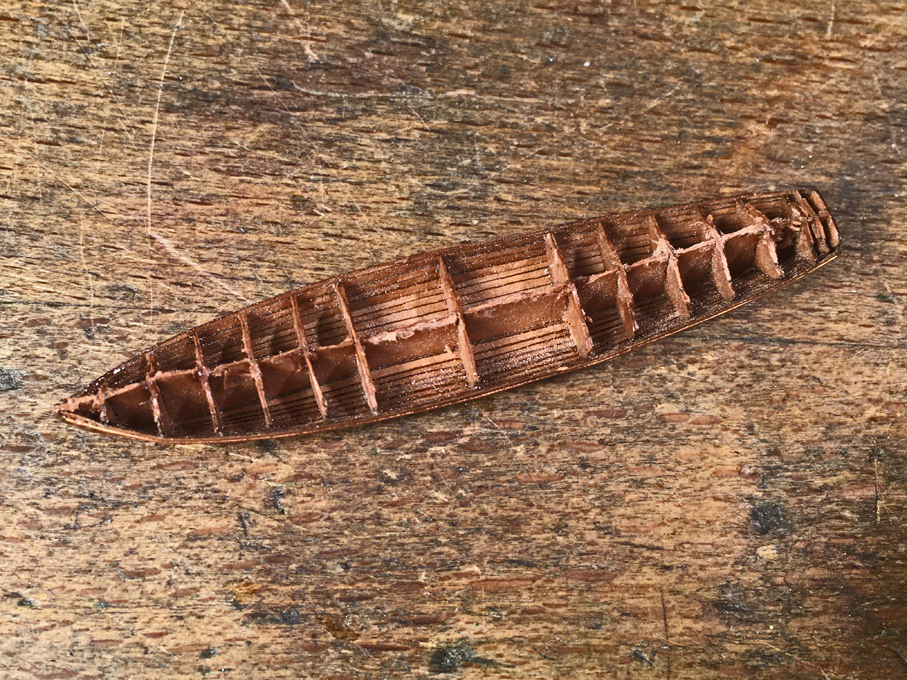
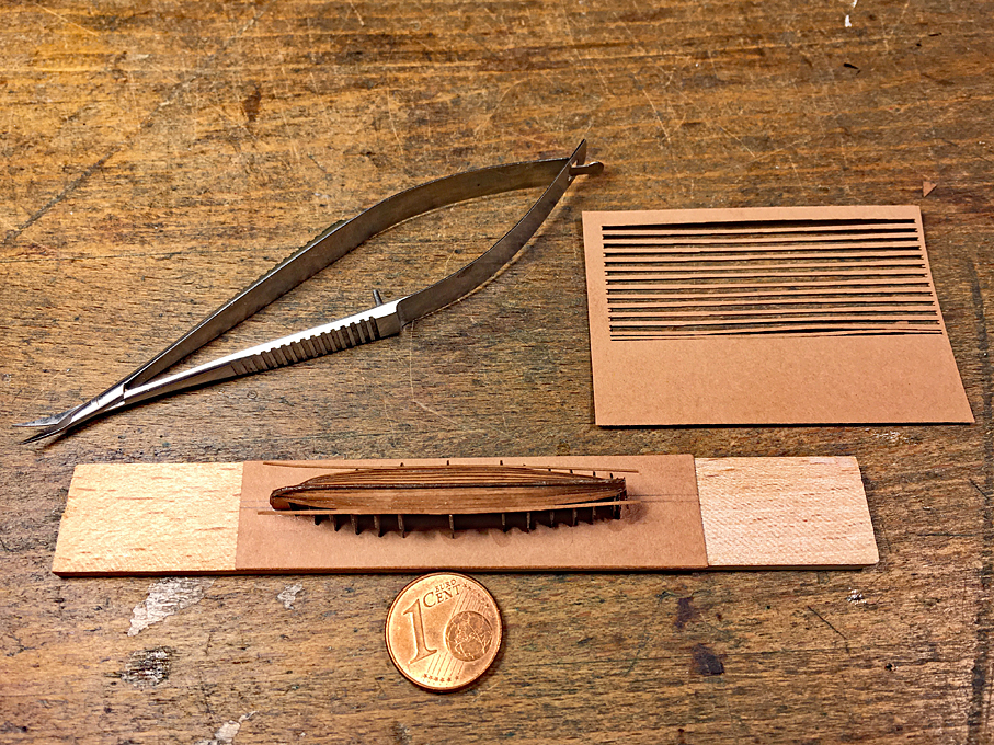
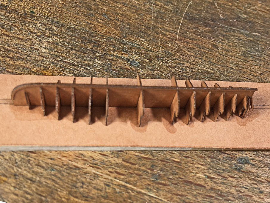
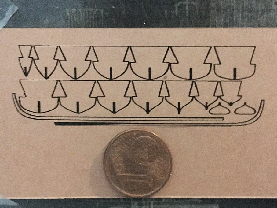
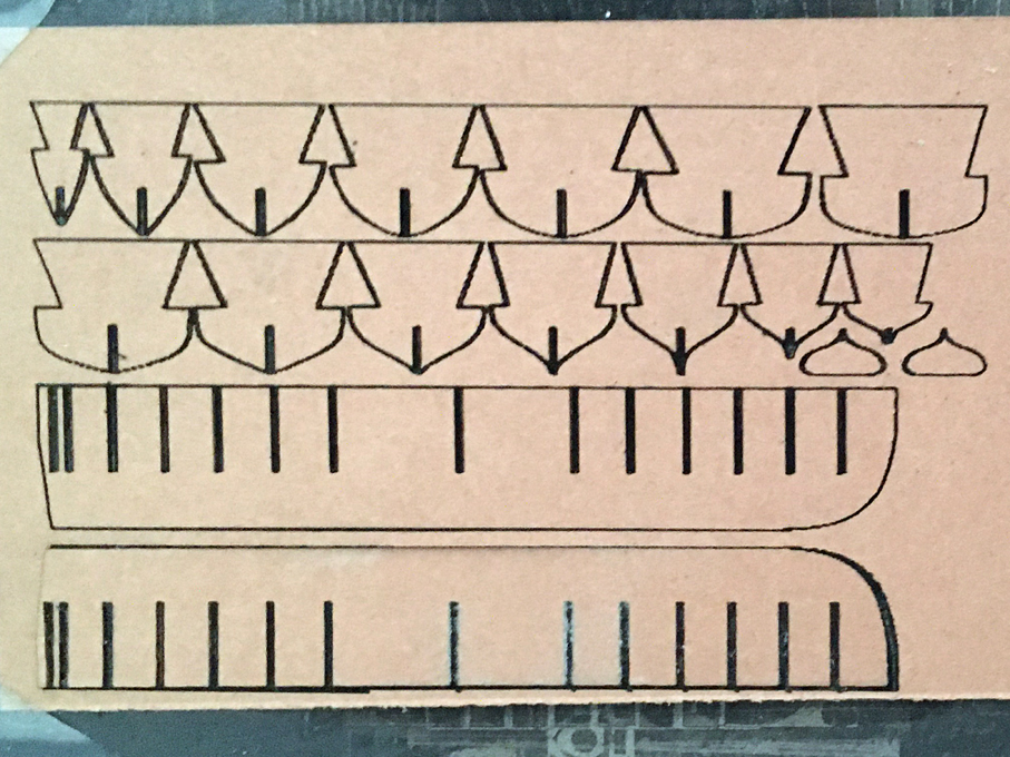
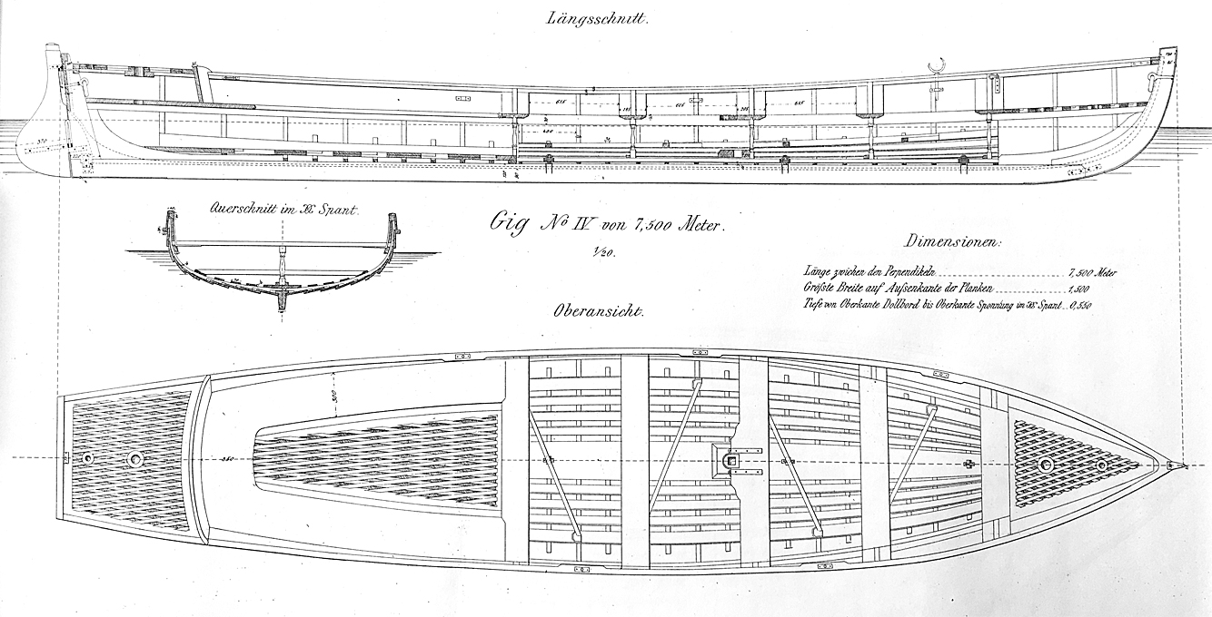
Ship’s Boats While I was waiting for the wire for the chain-rails to arrive, I turned my attention to the ship’s boats. At that time there were four, two class IV cutters, a gig, and a joll-boat. In 1:160 they are all less than 50 mm long and 10 mm wide. Thanks to some research of various colleagues in Germany, we have reasonably good information on these boats, including lines and their constructional arrangement. In addition, there has been a text-book on boat construction, published since 1878 with updates every few years until 1929, which gives quite a few details on the naval boats. I don’t quite feel like building four boats with all their internal constructional and fitting-out details, so I decided to show three of them covered, ready for the sea, while the small joll-boat will be shown ready for launching in an emergency, as it was custom. I don’t actually know, whether this boat or one of the cutters was used for the purpose, but assumed that the smaller boat would be easier to get into the water in a hurry, say in case of man-over-board. An additional challenge is that these boats were clinker-built. I once built a clinker-dinghy in 1:60, which was only 50 mm long, but it was much wider and deeper and with wider strakes. These boats typically have ten strakes on each side. I picked the long, but narrow and shallow gig first. I had a body plan available, drawn by a colleague some years ago. In addition, the text-book (BRIX, 1883) provides constructional details. The text indicates the dimension of the various parts. Drawing of gig from Brix (1883) I decided on an overhead plank-on-bulkhead (POB) construction, which in a way seemed easier than trying to carve the hull with its hollow lines aft from a solid piece of wood using templates. The individual framing stations were taken from the body plan and drawn with additional material on the top in order to arrive at a common reference plane for overhead construction. The bulkhead were laid out for laser-cutting from Canson-paper. Laser-cut bulkheads and keel-pieces A second drawing for laser-cutting contains another set of bulkhead and doubling pieces for the keel and stem, so that a rabbet for planking can be created. All pieces are doubled up after soaking in varnish to stiffen them. 2nd set of laser-cut bulkheads and doubling pieces for the keel and stem The pieces then were assembled as is tradition for POB-construction and mounted onto a piece of Canson-paper for extra stiffness. The whole assembly will then mounted in turn on a piece of wood to ease handling. So far so good, but planking will be challenge, as the individual planks will be less than a millimetre wide overall. In theory, they should be only 0.06 mm thick in 1:160 scale, but I will give it a try with the 0.15 mm thick Canson-paper and see what it will look like. If the planking looks to coarse, I will have to start all-over again … The assembled parts for the POB-construction Tapering such planks by hand would be too much of a challenge an not quite feasible in paper I think. However, my 2D-CAD program gives the length of the Bezier-curves used to draw the outline of the frames. So, I simply took this length, divided it by 10, divided the result by 4 and then multiplied it by 5, which gives the plank width at each station line assuming that they overlap by about a quarter of their width (according to the drawing in BRIX, 1883). The contours of the planks were drawn for laser-cutting with this information. A first run, was not so successful – I will have to optimise the cutting parameters. BRIX, A. (1883): Praktischer Schiffbau – Bootsbau.- 38 p. + 15 pl., Berlin (Hütte). To be continued ....
- 935 replies
-
- 17
-
-
-
Man-made fibres tend to be water-repellent or at least their wetting behaviour is not as good as natural fibres. That's why a solvent-based lacquer/varnish (including shellac) is a better option. Personally, I prefer what is zapon-varnish as used on silver- or brass-ware to prevent tarnishing. It is colourless and remains somewhat flexible (in comparison to shellac). Every varnish that really soaks in and does not stay on the surface as a coating will deepen the colour of materials ('ropes' and wood). This is normal and a physical effect of light guided (like and optical fibre) into the pores, rather than being reflected.
-
I may repeat myself, but I would rather use some fast-drying solvent-based varnish. I soaks in better and can be easily loosened with a drop of acetone or the respective solvent, if it needs to be adjusted.
