wefalck
-
Posts
6,643 -
Joined
-
Last visited
Content Type
Profiles
Forums
Gallery
Events
Everything posted by wefalck
-
Check out 'archjofo's' thread on LA CREOLE, a French ship of approximately the same period. Don't get daunted by the quality of his work, but take it as inspirational and benefit from his research. If you work backward through the postings, you will come to point (not that long ago), where he discusses the feature you are talking about. I have to check, I may have some images of the model of LA TOULONNAISE in the Musée de la Marine in Paris. If I am not mistaken the kit is based on a set of plans published by the 'Friends of the Museum': https://boutique.aamm.fr/monographies/plan-toulonnaise. The model and the plans in turn are based on a set of drawings published by Admiral Pâris in his 'Souvenirs de la Marine'.
-
 Coming on nicely! Will you leave the deck like that or still scrape? It looks rather glossy, actually. Using steel-wools also give a nice matt finish.
- 180 replies
-
- 1
-

-
- pilot boat
- Elbe 5
- (and 3 more)
-
Looking very good! I know, I forget this myself all the time, but it would be useful to have something to compare the actual size with.
-
Fixing paper to timber
wefalck replied to Boccherini's topic in Building, Framing, Planking and plating a ships hull and deck
You can also slide one of these thick razor-blades with reinforced back between the wood and the paper. That helps to peel it off, even when it has been on longer. -
I think this is a very good idea to transfer the curve of a plank to another one, sort of a parallel marking out tool that boat-builders use for the same purpose. I'll have keep that in mind for my next project, where I will have to handle 2 mm wide planks.
- 1 reply
-
- 4
-
-

-
Ras, why are you concerned about the staining of dowels? What did you make from dowel-rod that needs to be stained, rather than painted ? The funnel looks good! It doesn't really matter what's inside, as long as it looks right from the outside. I would give the paper a coat of wood-sanding filler - works also with paper. When using a wooden dowel as core for making paper tubes, I rub it with candle wax and then melt it down with a hair-dryer or a hot-air gun. You can also use Teflon-spray, if you have any.
-
A method for making panelled sails using paper
wefalck replied to Cathead's topic in Masting, rigging and sails
If I remember correctly, there are fly-tying threads (e.g. 18/0 from Veevus or Caenis) that are even thinner and also available in suitable colours. However, a 0.1 mm thread would be in say 1/48 scale equivalent to nearly a 5 mm rope, which is not what was used to sew bolt-ropes to sails. Hence, any sewing in scales below 1/24 or so would be grossly out of scale ...- 49 replies
-
- 4
-
-
- sails
- sail panels
- (and 1 more)
-
When I read the second line of your post, I first thought you were now working on 1:1 scale equipment ... I admire you, that you keep going under such taxing circumstances - isn't Zaporizhia just NE of Kiyw ?
-
Sorry for asking ... a bit of 'petrolpunk' then ... What is interesting is, that there is a bit of cultural and technical history around the quarries in the UK. Over here on the continent, at least in Germany and France, this is largely forgotten with little, if any photographic evidence, let alone books about the subject. In Germany there were a couple of manufacturers that made such small petrol locos for quarries, agricultural estates and the likes, but I wonder, whether any quarry had enough engineering resources to make such home-grown locos. Another reason for their absence (in my perception) may have been the rather strong workplace H&S supervision, at least since WW1.
-
Just like in full-size practice, except that hollow marlin-spikes are typically only used for wire-rope.
-
Did you explain in an earlier post, what these 'fiddly bits' are? Apologies for asking, if you did. Anyway, they look like nice pieces of small-scale engineering 👍
-
Keith, I was looking at the wrong kid, I thought you meant to boy at the left, I didn't notice the small kid in the centre ... The dog looks quite big for a mascot, but it seems that it was quite common in the navies to have cats (against the rats) and dogs or even exotic animals on board.
-
Good photographs, showing a lot of useful period details 👍 The very first photograph seems to be a photo-montage ... the capitain was copied indvidually from officier group photograph. I gather it was not someone's child on the other photograph, but a 'boy' (apprentice) and perhaps the ship's dog - many ship had mascots on board.
-
Nice job on the hull so far! Using styrene for parts that are painted saves you a lot of sanding and other preparation. Don't know, how soft the rubber of tires on your tractor is, but on parts like this I use a coarse diamond burr or wheel in the hand-held electric drill to remove flash.
-
As I said earlier, I would assume that this was a carronade barrel mounted on a sliding carriage. The lower part of the sliding carriage pivots (swivvels?) around a 'fighting pivot' during action. There does not seem to be any information, where this pivot was located. I am not sure, whether in 1828 traversing carriages already existed, meaning that the carriage had lugs for the pivots at both ends and by placing pivot-stubs on the deck at suitable points so that you can move (swivvel?) the carriage into different positions, while always having at least one pivot engaged - make the operations much safer than moving around a 'loose' cannon. Typically the gun would have been stored using two pivots in the centre-line of the ship and then moved into action position at the bulwark. I don't think that in 1828 central pivots already existed, but I may be wrong. If the carriage was pivoted centrally, then gun would have been just turned into firing direction, without the carriage being moved around. A smooth-bore gun can be loaded with pretty much anything of which you think it would inflict the desired damage to your opponent. In case of solid shot or shells, you just need to make sure that it fits with some clearance (for which there were rules or calipers set for each gun with which each shot or shell would be checked before loading. A 'wad' between the powder and the shot ensures a gas-tight seal - unlike in a modern breech-loader, where the projectile has a soft metal ring that provides the seal.
-
Looking good ! As you have a lathe, I am wondering, why you build up the goose-neck for the sliding gunter from tube-sections, rather than boring and turning it from a piece of round brass?
- 153 replies
-
- 1
-
-
- Ancre
- Bruno Orsel
- (and 2 more)
-
What surprises me, is how fragile these coaches looked. OK, they had to keep weight down so as not to tire the horses too much, but somehow it is difficult to imagine these things going along mud-tracks.
-
@druxey You are probably right, but I used the materials that were at hand. In addition, I am rather limited in display space, so I wanted to keep it small 😊
-
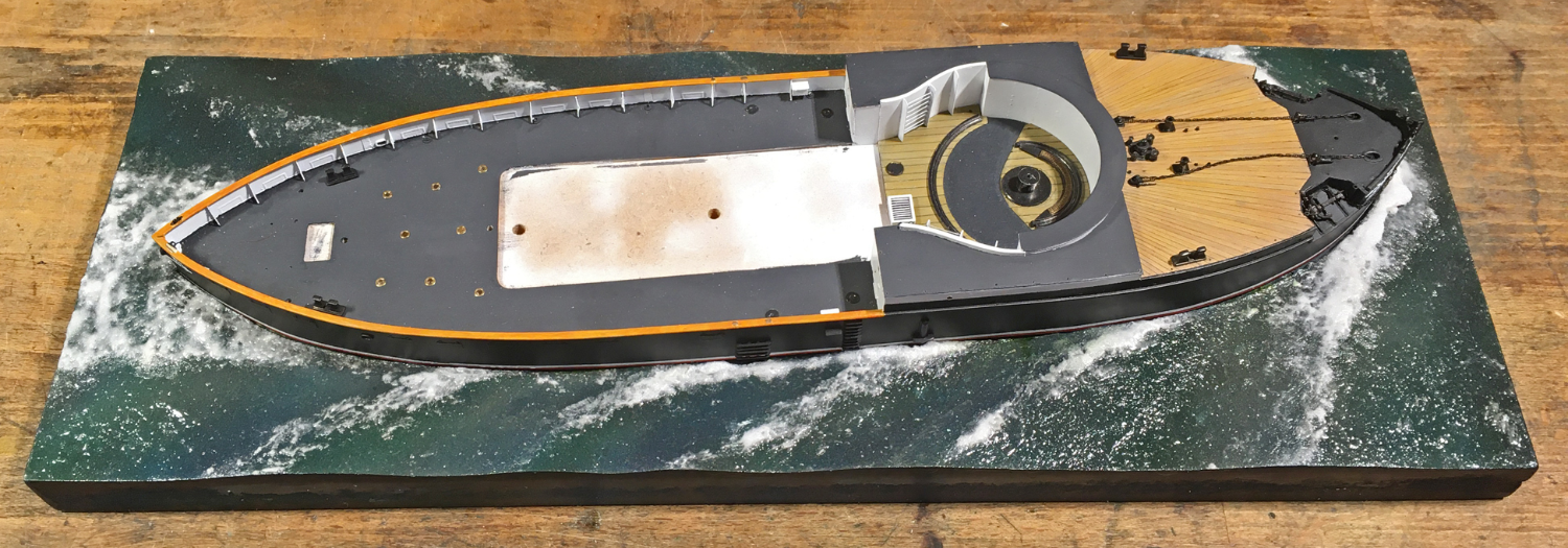
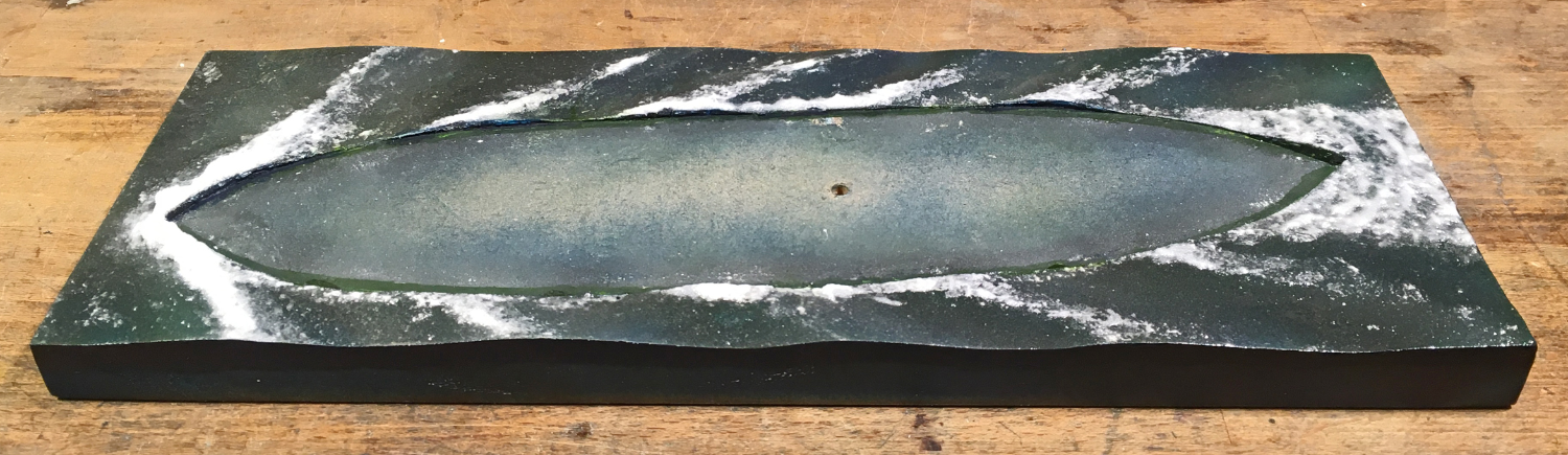
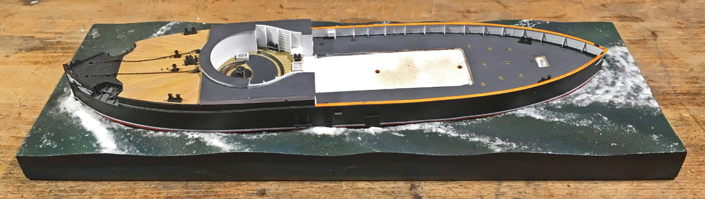
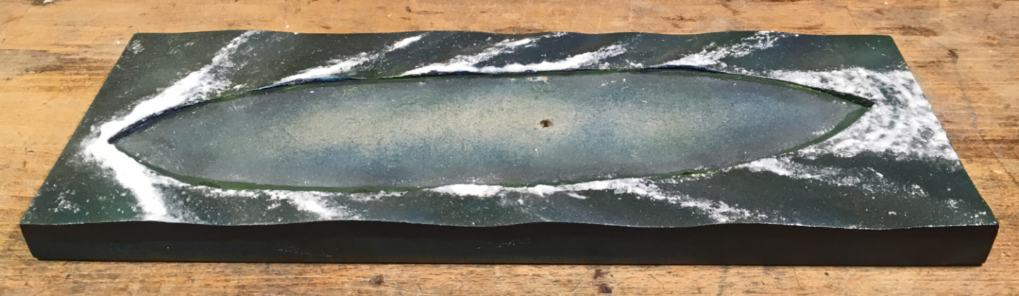
Thanks again too all for your continued moral support ! *********************************************** Mounting the model In another thread the question was raised as to when (permanently) mounting the model. It is a question of scale, of course, and also whether we are looking at a full-hull or a waterline-model. Smaller scale model can be very delicate, while larger scale models tend to be inherently more robust. A waterline-model may not offer you a lot of positions from which you can grab it during construction and final mounting. So, in general, it will have to be done earlier than for a full-hull model. In this particular case, adding more delicate items, particularly also those outside the hull, would make it almost impossible to handle the model without damaging it. Therefore, it was decided to prepare the mounting now. The base-plate, a piece of 20 mm thick, MDF, forms an integral part of the display case that had been constructed earlier. To this the model will be fixed with a single wood-screw from the bottom. The hole in the model for this had been drilled early on in the construction process. I did not envisage to have to mount and unmount the model frequently, otherwise I would have embedded a threaded nut into the bread-and-butter hull and used a machine screw instead. With hindsight, I perhaps should have extended the hull a bit more than just 2 mm below the waterline. The 2 mm are not that much to model the sea, but would translate into a wave-height of around 32 cm or a good foot. The scenario I imagined for the presentation is that the ship moves in a rather calm sea, but at moderate speed (the max. speed of the WESPE-class was only around 10 kn anyway). The weather is fine, with sun and a light breeze – a summer day on the North Sea or the Baltic. There is only one image I am aware off, that shows one of the boats moving, S.M.S. NATTER moving slowly along the Kiel-Kanal. Therefore, we do not really know what their wave-pattern would have looked like. The bow is quite full, it has a ram protruding below the waterline, and hard bilges with a flat bottom. In a way, this is the form of our river freighters. Therefore, I looked around on the Internet for pictures that show such ships on the move. Of course, there is a difference in wave patterns due to the restricted water depths in river channels. The wake would be more or less a Kelvin pattern with the waves radiating from the ship with an included angle of around 40°. The base is not much bigger than the ship to allow close-up view of the model, so there is actually not so much sea to model. Base-board covered in moulded water-colour paper and primed I decided to try something new (for me) and instead of sculpting and carving the sea from plaster of Paris, as I had done in the past, I used a sheet of thick water-colour paper. The waves were formed by placing thin scraps of acrylic foam (because I happen to have some) underneath and then gluing it down with white glue, working from the bow to the stern. The space for the model was cut out first, of course. Once the glue set, the paper was trimmed to size. The gaps under the paper were filled with acrylic wood-repair putty and the edges sanded smooth once the putty had set. At this stage also the fit of both, the model and the display case were checked and small corrections made. Finally, the whole base was given a coat of sanding filler to seal the paper and the wood. The edges were sanded smooth again. Base colouring sealed with gloss varnish Painting proceeded in several steps. First a coat of Schmincke AeroColor turquois acrylic was applied by airbrush. However, the paint was applied in a glancing fashion against the direction of the waves. A second coat using Vallejo ModelAir ‘steel blue’, again glancing, but with the waves was applied. Here in this application, it is not really apparent, but when there are shorter, steeper waves modelled this causes a colour change effect, when you look at the sea-scape from different angles. The front of the waves then was lightened up somewhat by a light spray of Schmincke AeroColor chrome-oxide green and the crest areas further lightened up with a light dust of Vallejo ModelAir ‘hemp’ to give the sea a flatter green appearance. This base colouring was sealed by two generous coats of acrylic gloss varnish applied with a flat hairbrush. In the next step, the wave crests were modelled using acrylic gel and gel filled with acrylic ‘micro-balloons’. In the past I actually used crystal sugar as a filler, which works very well, as not all crystals dissolve, but remain as transparent parts. I used this even before I became aware of acrylic gels together with wallpaper-glue and this ‘icing’ is holding up well after 40+ years. Part of the bow-wave was sculpted again in this way. Sea-scape with wave-crests sculpted in filled acrylic gel With the sculpting of the wave-crests and foam stirred-up complete, the sea-scape was given several more coats of gloss varnish to smooth it out, playing also with more rough areas behind breaking waves, as these should appear more matt. Assuming that the top of the waves would be more exposed to the action of wind than their front, these areas were also stippled with acrylic gel using a bristle brush, simulating the wind rippling that indicates an incoming gust of wind to the attentive sailor. S.M.S. WESPE placed temporarily into the sea-scape Having prepared the sea-scape in this way, the model will not yet be placed irretrievably into it. Filling the gap between the sea-scape and the model with acrylic gel will be left to the very end, so that the model can be removed, should the need arise. S.M.S. WESPE placed temporarily into the sea-scape To be continued ....

- 935 replies
-
- 22
-
-
-
3d printing crew figures
wefalck replied to highlanderburial's topic in 3D-Printing and Laser-Cutting.
Painting skin is always a challenge because of its translucency. Building up the colour from washes is what artists do indeed. The darker the skin is the more difficult it becomes, as the contrast range dramatically decreases compared to fairer skin. I believe there are books available on the subject and surely also tutorials on on the Internet on portrait painting (rather than figurine painting). The Old Masters, it seems, often used an underpaint of pale green for skins as this increases the brilliance of the following reddish washes. Whether this would work with dark skins, I don't know. However, as one can see from the not too many paintings available, the Old Masters were struggling with the low dynamic contrast range of dark skins, which then often looks flat. -
A method for making panelled sails using paper
wefalck replied to Cathead's topic in Masting, rigging and sails
We had this discussion already in another thread some time ago: If you can use such needle threaders on blocks this means that the holes in the blocks are too big for the 'rope' and/or that the 'rope' is too soft and can be squeezed too much. The holes should be about 10% wider than the nominal 'rope' diameter. I would follow Mark's advice and stiffen the tip with varnish and then cut it to a point.- 49 replies
-
- 5
-
-

-
- sails
- sail panels
- (and 1 more)
-
Good to hear from you and that you keep your spirits up in spite of the dire times ✌️
-
Yes, it seems that other nations soon began to copy the carronades - no international patents and IPR protection then ... For a short period, carronade-type guns were produced with trunnions, rather than the later ubiquitous lug at the bottom. See: DELAUNEY, J.F., GUITTARD, A.C.A.J. (1889): Historique de l'artillerie de la marine 1692-1889.- 328 p., Paris (D. Dumoulin). LAFAY, J. (1850): Aide-memoire d'artillerie navale.- 721 p., 50 pl., Paris (J. Corréard).