wefalck
-
Posts
6,643 -
Joined
-
Last visited
Content Type
Profiles
Forums
Gallery
Events
Everything posted by wefalck
-
 Beautiful indeed! I think I have seen these quite strange seating pads before on photographs and wondered, how comfortable they actually were - afterall our bottoms have two bulges and a depression in the middle, while the seats have a depression in the middle and raised edges all around ...
 -
Looking at the anchor pump-spill above, the levers appear to be rather short - the men would need to lean over the spill and would not have a lot of fulcrum. I think the handles should be outside of the spill-heads so that the men can stand clear of them - or do you have images that show the handles to be so short?
- 180 replies
-
- 3
-

-
- pilot boat
- Elbe 5
- (and 3 more)
-
"(lacquer thinner, gloss)" - not sure what you mean by this. The acrylic paints I know I normally thinned with water. And why 'gloss'?
-
Enamel over acrylic in general is ok, as it follows the rule 'fat over lean' (making reference to oil- or other hydrophobic content), but the acrylics have to be thoroughly cured, as it may take weeks for any residual water to diffuse out. Another potential issue is that the solvent in the enamel paint may attack the acrylic paint. It is always wise to do some tests. However, this begs the question, why you want to use enamel paints for weathering, while this can be done perfectly well with acrylic washes, even without buying any special 'weathering' sets, if you have a basic set of colours already. Personally, I prefer paints readily diluted for air-brushing that can be applied easily as washes with more or less water. Another option are basic pastels, white, black, grey, and a reddish brown and/or burnt umbre.
-
It's probably not very nice to point people to other fora, but this topic is more extensively discussed here: http://www.shipmodels.info/mws_forum/ You can get silver wire down to 0.007 mm diameter, copper down to 0.05 mm and molybedenum (difficult to cut) down to 0.01 mm. Some people also advocate stretched styrene sprue ...
-
Painting the hull
wefalck replied to Steve47's topic in Building, Framing, Planking and plating a ships hull and deck
BTW, GORCH FOCK has a steel-plated hull, having been built in 1958 ... -
And there are many 'false' friends in Spanish - you think you know what it means, because in Italian, English, French and German a word with Latin roots has one and the same meaning, but in Spanish strangely enough, it may have a rather different meaning ...
-
Nils, what I meant is that the stern-post may sit vertically on the keel - like on the schooner, rather than running in a curve into the keel. The end would be still pointed, but the stern-post more or less vertical. This a possibility, one would need to verify this against images. I think there are paintings and photographs of the Elbe-pilotboats that show the rowing-boats in the davits.
- 180 replies
-
- 2
-
-
- pilot boat
- Elbe 5
- (and 3 more)
-
I think you will have to cut away the foil from the stem-/stern-post ... normally the planks would fit into a rabbet there. Are you sure that stem and stern were really symmetrical? Typically, in double-ended boats the dead-wood under the stem is cut away somewhat, while the stern-post sits more or less vertical on the keel. This allows to have the fingers for the rudder deeper down and also adds to the directional stability while rowing. On surfboats the stern-post dead-wood may be cut away, but not on these pilot-transfer boats - they often had to be rowed back to the pilot-schooner by one man only, when directional stability is even more important.
- 180 replies
-
- 3
-
-
- pilot boat
- Elbe 5
- (and 3 more)
-
Planking glues
wefalck replied to ChiefCarr's topic in Building, Framing, Planking and plating a ships hull and deck
Just thinking: as it is RubberCement®, you migh be able to peel off the 'planks' one by one, clean the area (not sure what solvent works on the stuff) and place the plank back with PVA glue ... in this way, you keep the nice layout and if you break a plank, you can use the bits as template to make a new plank to fit nicely into the gap. -
Valeriy, what I meant is how did you turn the brass parts silver, by chemically tinning them for example?
-
Have a look at fly-tying threads. The thinnest is 16/0 two-ply from e.g. Veevus, which is available in various colours. From this you can make a proper 'rope' using a ropewalk, which would be about 0.1 mm in diameter. Personally, I like to give all standing gear a light final wash in diluted acrylic burnt umber paint. During rigging I secure any splices and knots with a solvent-based varnish so that I can undo things, if needed.
-
I personally would soft-solder the trunnions into the barrels. Just pre-tin the trunnions a bit in the middle, sand down (if needed) to fit the them into the hole into which some flux has been dropped and heat up the barrel. Make sure to remove any excess solder that is visible, as it may impair the blackening process. The soldering will survive the wire-brushing, pickling and degreasing before the blackening better than CA. Blackening must be protected with either lineseed oil (not recommended due to the long drying time) or a varnish. As the barrels would have been normally painted in black oil-paint, I would use a satin varnish. You can use this varnish also to cement on the pre-blackend coat-of-arms etc. There are reputedly some blackening agents that also work on soldering tins. If you have one of those, you might also lightly solder on the coat-of-arms, assuming that it is a part photo-etched from brass.
-
Planking glues
wefalck replied to ChiefCarr's topic in Building, Framing, Planking and plating a ships hull and deck
This 'yellow glue' seems to be a Northamerican specificity. I didn't hear about it until joining this forum. Over here in Europe (or at least Germany) we use 'white' (PVA) glue, unless you really go for the old-style carpenter hide-glue. 'Rubber cement' in this context also would worry me, as I understood this to be a something with which you mount pieces of paper temporarily, so that you can be peel them off after a while. Anyway, it is a nice tight planking job, that would deserve to be reinforced with dowelling to make it long-term stable. The dowels should be dunked into white (yellow) glue to keep them in place. I found it always somewhat strange that people comment on someone having done a good job on a 'first' - why not, when someone works carefully, with patience, and follows the recommendations e.g. for planking layout? Also we don't know what other (woodworking) experience the person may have had already. -
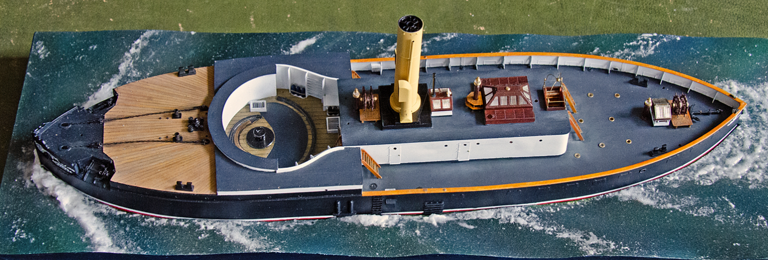
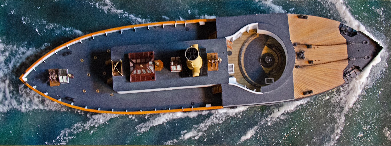
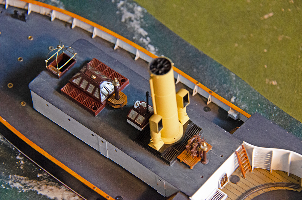
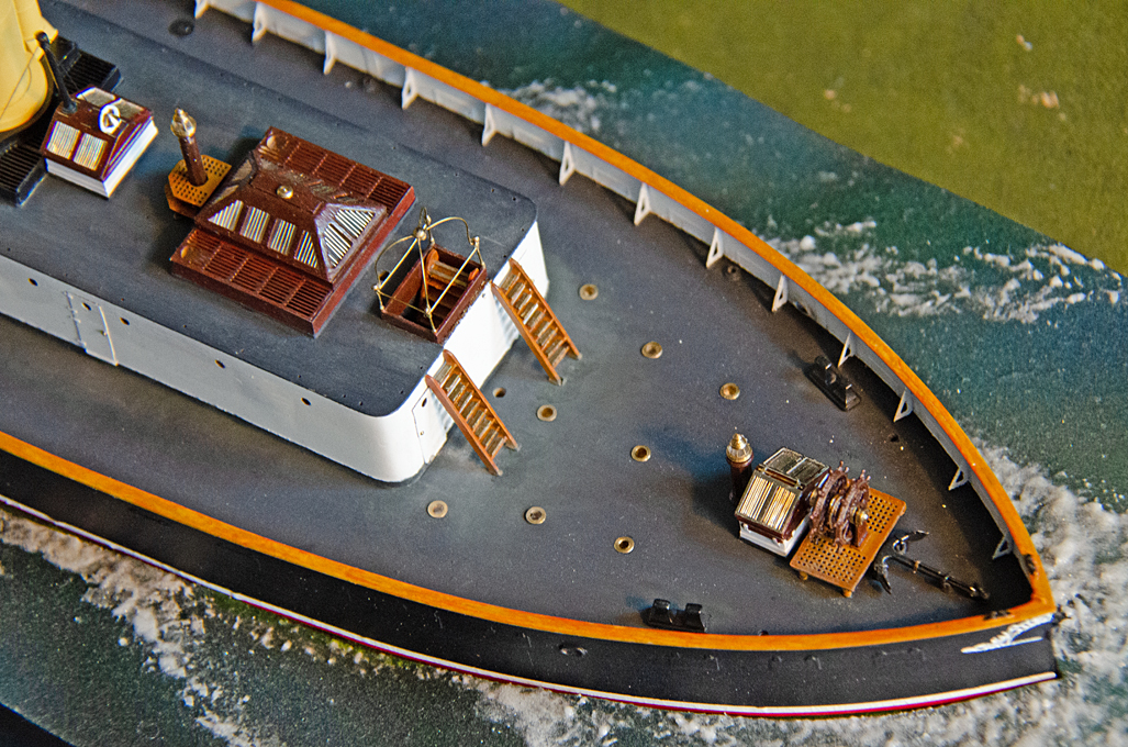
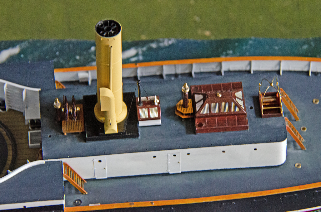
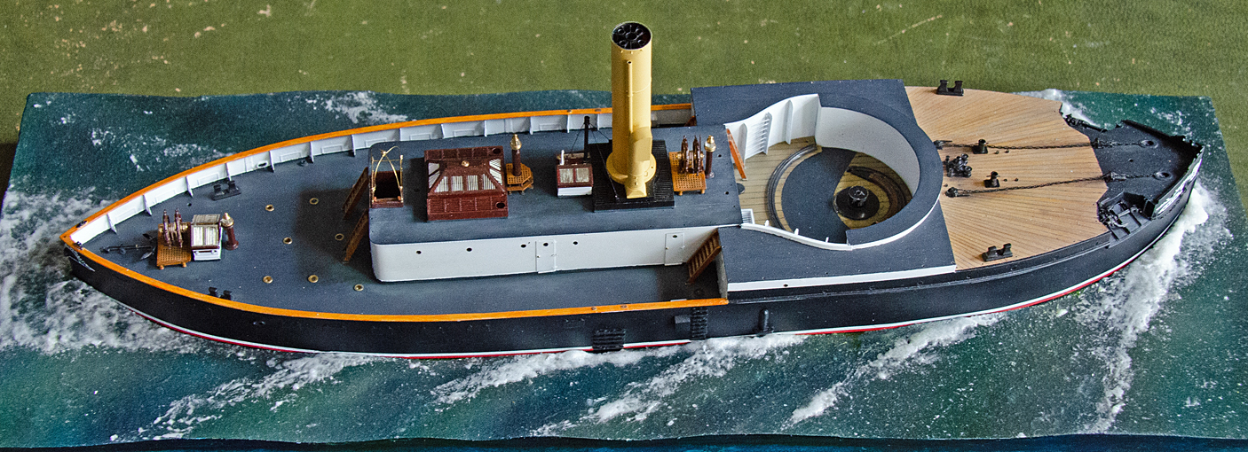
Thanks to all for your kind words and the 'tumbs up' ! ********************************************* Beginning putting everything together Over the years many parts have been produced and more recently painted. It slowly time to put everything together. The first step was to semi-permanently install the boat in the seascape. I do not expect to have to remove it again, but one never knows, so I am leaving filling the gaps around with acrylic gel to the very end. The model was screwed to the base from the bottom using a single wood-screw in the middle. At this point also the deckhouse could be permanently installed. Which in turn allowed to install the various ladders. These had been fitted with ‘brass’ anti-slip pads and shoes to keep them in place. The various skylights also have been installed and the steering-wheels together with the associated binnacles. The seams between the deckhouse, the skylights and the decks were touched with paint and some light ‘weathering’ with pastels applied with the idea to ‘pull together’ all parts visually. Thus, corners were touched up in dark grey pastel and typically more worn areas in front of ladders etc. were given a light rub with white pastel. This has to be with restraint, as the boat is meant to be depicted in a relatively new and well-maintained state, around 1878, so not much rust etc. BTW, the model is 286 mm long or 11 1/4 " ... To be continued ....

- 935 replies
-
- 27
-

-
-
Yes, that’s a point. Somewhere between 25 and 30 cm thickness sounds about right for a vessel of that size.
- 180 replies
-
- 2
-
-
- pilot boat
- Elbe 5
- (and 3 more)
-
Nils, a standard M3 nut is 2.4 mm thick, which gives you about 5 threads for a pitch of 0.5 mm. However, given the size of the model, I would feel more comfortable with M4 or even M5 …
- 180 replies
-
- 2
-
-
- pilot boat
- Elbe 5
- (and 3 more)
-
Looking solidlly done - deutsche Wertarbeit Why don't you use an ordinary nut and large washer ('Karosseriescheibe'). That would be easier to tighten than these press-in nuts.
- 180 replies
-
- 1
-
-
- pilot boat
- Elbe 5
- (and 3 more)
-
These bilge-keels are rather large for a motor-launch, I have feeling. They are as big as those in sailboats for tidal waters, that are meant to sit upright on them in the mud. I also wonder, what will happen to the prop-shaft, when you hit something with the 'protective' pin sticking out from the bearing? It will probably bend the shaft ... or will there be a bar connecting this to the keel-fin?
-
Not a bad idea at all ... but you also need a groove for the shroud on the outside, which you probably can file. If you actually needed round dead-eyes (as per 17th century onwards), you could solder three smaller pipes into a larger one. On the other hand, if you don't like wood for them, you could also cut disks from a brass- or styrene- or acrylic rod and then drill the three holes in a simple drilling jig.
- 396 replies
-
- 6
-
-
- Idea
- Bright Idea
- (and 1 more)
-
Never ... well, I think brass or perhaps rather bronze or cast-iron came into use when wire runners came into use, for which even Lignum vitae was too soft. I believe expensive brass sheaves and ball-bearings came into use also on later 19th century yachts.
-
Lighting upgrade to Proxxon band saw
wefalck replied to Kevin Kenny's topic in Modeling tools and Workshop Equipment
Such LED flood-lights are useful for eyes getting older - I installed one above my workbench a while ago as well. One can never have enough light ...