


wefalck
-
Posts
6,643 -
Joined
-
Last visited
Content Type
Profiles
Forums
Gallery
Events
Everything posted by wefalck
-
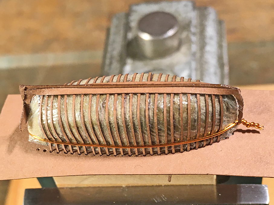
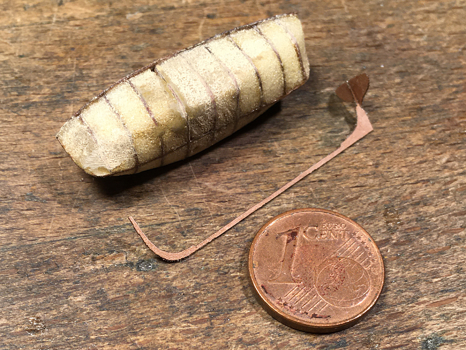
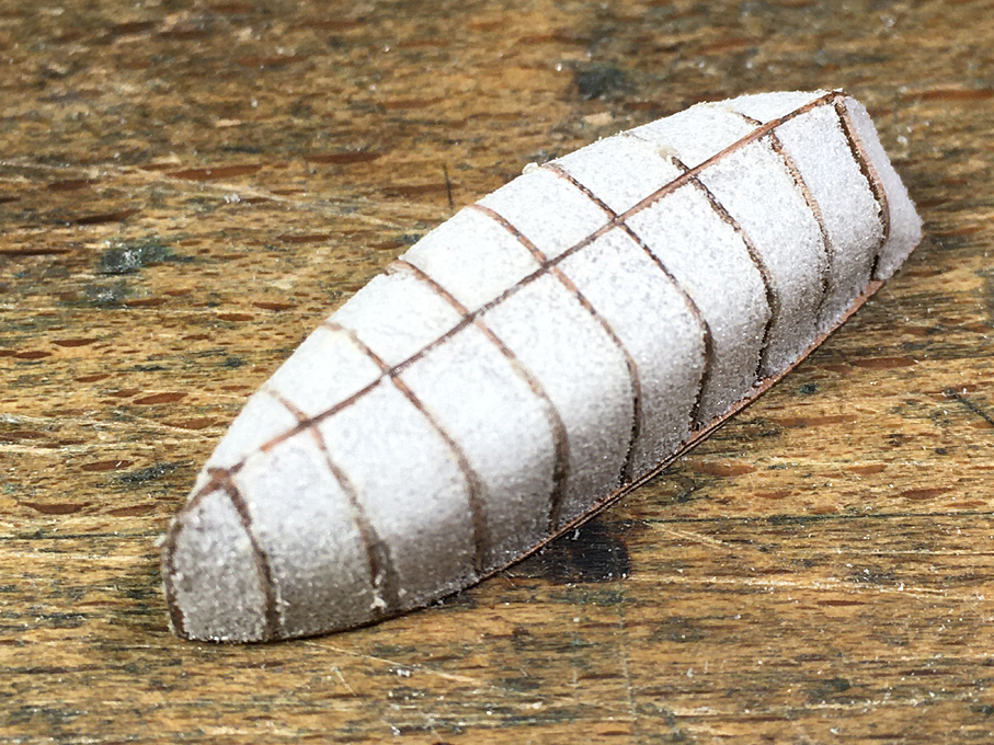
 Apologies to all, who visited over the past three weeks this building log and found that nothing happened. Real life gets in our way quite often and also a bit of travelling for fun … ******************* Jolly-Boat continued The main pieces for the core over which this boat will be constructed as plank-on frame build were laser-cut from Canson-paper and assembled in the manner described previously. The spaces between the bulkheads were filled with hard acrylic foam (Rohacell™) and the foam sanded back to the bulkheads using diamond needle files. Some gaps were filled with putty and then the whole thing soaked in wood sanding-filler to provide a hard surface. Core for the POF construction The keel-stem combination and the transom were also cut out by laser in two copies to be stuck together to arrive at the correct thickness. The back-bone of the jolly-boat A base’board’ for building was cut from the same paper in double and the two copies stuck together for more rigidity. This baseboard had holes laser-cut in for the bent frames in order to give the exact spacing as per plan. The core then was covered in a layer of cling-film to prevent the lacquer to be used during the construction from sticking to the core (hopefully). Using again very thin double-sided mounting tape, the core was stuck to the baseboard. The bent frames were cut using the laser to the required width of 0.2 mm which translates at 1:160 scale to a width of 32 mm. They should be only 0.1 mm thick (15 mm in the original), but the paper is a tad thicker. These frames were inserted into the pre-cut holes and aligned carefully. Then the keel-stem-transom assembly was lacquered into place. It should be noted that there are a couple of cant-frames that but against the keel/stem, rather than running under it. The framed structure It should be noted that this is the reverse construction order compared to the original. The clinker-built boat would be built over a couple of templates, with the planks going in first and the frames bent in afterwards. I chose this method, because having the frames in place is likely to make a stronger shell, when trying to remove it from the core. The garboard-plank installed On any clinker-built boat the garboard-plank is the most difficult to install due to its torsion and bending. Here it was no exception. It needed a fair amount of coercion, but it looks promising. I only hope, that I will be able to remove the shell from the core in the end … To be continued ....
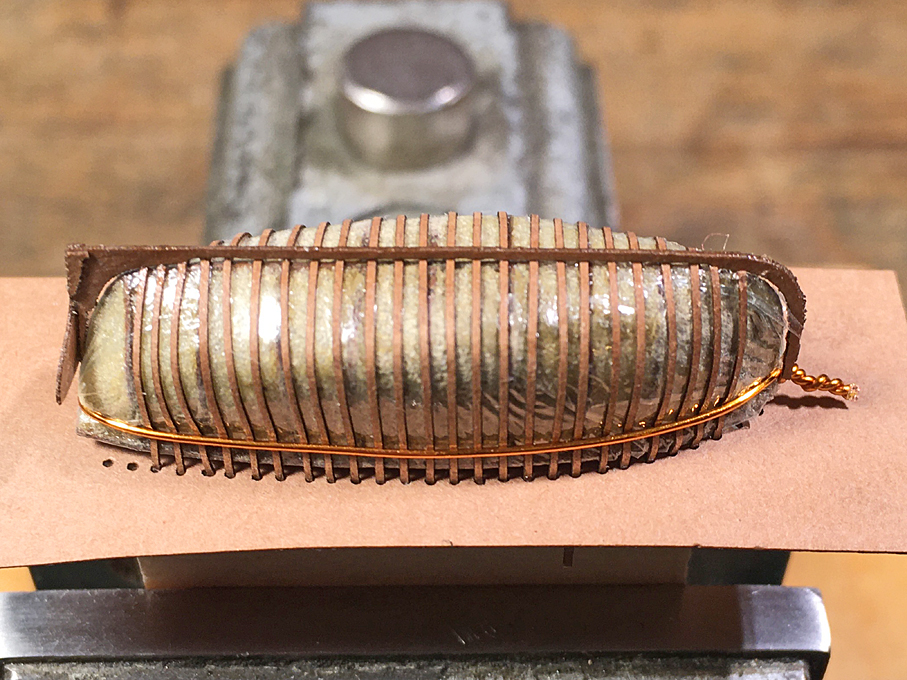

- 935 replies
-
- 18
-

-

-
Russel, would you have a picture of the material? Also what scale are you working in. I gather there are various fabric dyes on the market, I suppose (I do not know the US American market). Keep in mind, however, that tanned sails, where not just coloured, but they were smeared with concotions of tallow and yellow/red ochre, so the sails would appear rather smooth. One can simulate this by soaking the material with acrylic paint, so that it covers most of the weave.
-
Jewellery-making supply shops normally carry them (or at least list them in their catalogues).
-
It seems that your head scratching had similar effect as Samantha's twiched nose (remember 'Bewitched' ?): the engines are definitely coming along nicely 👍
-
Well, good tools in the right hands ... 👍
-
Yes, recycling material is always a good idea, but PET is not necessarily a good material for making durable models. Also, filament-printing is not the best choice, due to its low resolution in comparison to resin-printers. Making filaments from PET-bottles for printing in fact is only a slight variation of the normal recycling technique for such bottles: they shredded into small pieces, heated and then an extruder forms a new bottle - an extruder is nothing else, but a big printer that prints bottles ...
-
On colour-coded cordage: I suppose one could imitate that, when you make your own rope. One could add to one of the strands a length of the finest fly-tying yarn that is available in many different colours. Colour-coding, however, seems to be more common in braided rope, than in traditional one.
-
Nice progress ! As to the anchor-buoy: not sure what the guys then and there would have done, but normally the line would be hitched around the crossing-point between the arms and the shank.
-
Found a German Wikipedia-article about Baranovsky and learned something about the history of artillery 👍
-
I fully agree with the previous comments ! I have never heard of the Baranovsky landing-guns. This must be a Russian patent. Do you have more information ont them. Is it really a landing-gun, because the pedestal looks more like a ship's gun? Or is it to be dismounted and then mounted onto a landing-carriage?
-
I would echo the previous speaker concerning the praise! Didn’t realise before how complex the peak-halliard is. Haven’t seen anything like that before. A couple of bridles yes …
-
Glad to hear that you are in full swing again !!! Such pre-1880s subjects are rarely seen in railway modelling and there is almost nothing commercial available from that period, I think, regardles of scale/gauge. I am not an active railway modeller, but always thought that something from the 1860 to 1880 period would be nice to create ...
-
Victory
wefalck replied to Jake 1948's topic in Painting, finishing and weathering products and techniques
This article provides great insight into the dozen or more layers of paint identified on HMS VICTORY. They also tried to date the various layers, which led to the ship's current paint-scheme, I believe. Vale, B. (2020): Pitch, Paint, Varnish and the Changing Colour Schemes of Royal Navy Warship, 1775-1815: A Summary of Existing Knowlege.- The Mariner’s Mirror, 106(1): 30-42. This may be more reliable than more or less contemporary paintings. -
Eric McKee in his 'Working Boats of Britain' looked a bit into the mechanics/ergonomics of rowing and I think gives some dimensions, if I remember correctly, for spacing thwarts, inboard vs. outboard lengths of oars etc. Rowing efficiency, both from the purely physical perspective as well as from the physiological perspective is quite complex. While in the 18th/19th century, of course, there were no scientific studies on this, people had a lot of experience. I gather there are in principle x different rowing arrangements in ships' boats: - one man per thwart with two oars (in small boats only) - one man per thwart with one oar (single bank) - two men per thwart with one oar each (double bank) - four men per thwart with two men per oar (in large boats only) You will need an inboard length of the oar of around 3 feet minimum to give a reasonable fulcrum, whereby one hand is placed on the handle and the other more or less at shoulder width further towards the thole pins. This means that you would need a minimum of around 6 to 7 feet for a double banked boat, while a single-banked one could be as narrow as about 4 feet, with the men off-set to each side of the boat. Faster, lighter boats could have proportionally longer oars with wider space between the thwarts to allow for longer strokes, propelling the boat faster, while heavy working boats would have closer spaced thwarts with shorter oars, as here you need the 'torque' of the oars at slower speed.
-
Kind of inflatable 'camels' ...
-
This little ships got very crowded in places, particularly on the foredeck and one wonders how they managed to work them.
-
Of course, I didn't scroll back through the posts. I hope a good year later the hand is on the mend!
-
Experience shows, that in the modelling realm, these values are not so important. You will get a feeling for what works. It is different in the professional world, where efficiency is money.
-
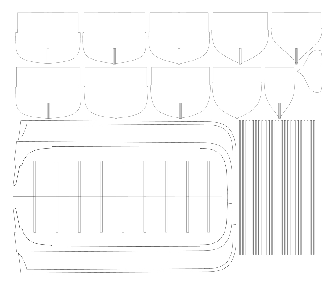
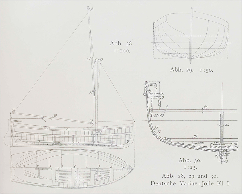
The shipyard has been on a somewhat extended summer-shutdown, including the drawing-office (which was not quite planned so, but the heat at my abode in Spain, just made me not feel like working too much on the computer …). Thank you very much for all the likes and encouragement that has been accumulating since the last update! ***************** The Jolly-Boat Rather than doing the second cutter, I am now tackling the jolly-boat. This is the smallest boat of the complement, at 6 m (= 19’8”). I am in for challenge, as I plan to build this open and fully equipped, ready to be lowered in case of man-over-board or a similar emergency. I did not find an earlier drawing, but the drawing in the 1911 issue of the ‘BRIX’ is quite detailed, although it is for the karweel-planked version, while I will kit out WESPE all with clinker-built boats. It appears that the frames are drawn to the inside of the planking, which is exactly what I need. The arrangements for the keel and stem-/stern-post will be somewhat different from what I did for the other boats, as the bulkheads will only act as formers. Drawing of Class 1 jolly-boat from Brix (1911) The laser-cut framework will be infilled with hard foam (Rohacell™) as before and then covered in cling-film to prevent the frames etc. from sticking to it. Below is the laser-cutting template for the main structural components. The thin strips on the right will become the ‘bent-in’ frames. Other parts will be drawn to fit as I am going along. Laser-cutting templates for the formers and main structural components of the jolly-boat. I will also need to still draw a base-board for the construction process, that has notches for the upper ends of the frames to rest in. To be continued ....
- 935 replies
-
- 11
-
-
Ras, sorry can't help you there with any substance. Looking through my list of literature, I found a couple of references that might be helpful: Anonym (1914): Nautical Terms - Motor Boats - Marine Gasoline Engines - Management of Marine Gasoline Engines - Motor-Boat Navigation - Motor-Boat Rules and Signals.- p., Scranton (International Textbook Company). - available as eBook, but I don't have the link anymore. OVERTON, G.L. [Ed.] (1926): Catalogue of the Collection in the Science Museum. Water Transport. VI. Marine Engines & VII. Marine Boilers.- ? p., London (H.M. Stationary Office). - I don't have a copy of this catalgoue, but you could have a look at the on-line resources the Science Museum in London now offers: https://collection.sciencemuseumgroup.org.uk/search/objects/categories/marine-engines?page[number]=1 I have also a few books on early German boat-motors, but this is likely not to be very helpful here. The (practical) pioneers for IC motors in boats were first the Danes and then the Dutch and Germans, I believe.
-
Small diameter gears
wefalck replied to bridgman's topic in Metal Work, Soldering and Metal Fittings
I found the clock- or watch-wheels are too thin and their teeth normally are too deep to represent such gears satisfactorily. Try to work out the number of teeth on the respective wheels by counting e.g. a quarter of the circumference, or whatever is visible. You then can try to find on-line some (old) engineering textbooks that give you an idea of the relative proportions of the teeth. On this basis you can draw on the computer an enlarged image of the gear (it's a lot simpler and precise to draw at 20:1 or 10:1 scale than at the original 1:50 scale). The print it out at the right size and stick two carefully aligned copies onto each side of the material that you are going to use. No you can use files or even a skalpel to shape the teeth. If on the model you won't be able to see parts of the gear, you don't really need to shape the teeth and save yourself time. Make sure that for meshing gears you draw the same 'modulus' or 'diametral pitch' (check on Wikipedia what this means). Of course, such gears probably wouldn't really work, but they can be a good representation - better than clock- or watch-wheels. -
How metal hooks are stropped onto block
wefalck replied to glennb17's topic in Metal Work, Soldering and Metal Fittings
In any case, in real practice it would not be possible to wrought the ring closed with the rope through (with or without thimble) - the heat would burn your rope. The same applies, when bending the hooks from wire and (silver-)soldering the ring closed. One has to follow full-size practice and splice the becket after leading it through the ring. In small scales, one may need to fake the splice and hide the joint under the seizing.
