


wefalck
-
Posts
6,643 -
Joined
-
Last visited
Content Type
Profiles
Forums
Gallery
Events
Everything posted by wefalck
-

Historical Teachers of the Modeling Craft: Davis vs Underhill
wefalck replied to SaltyNinja's topic in Nautical/Naval History
An isue with most of the books quoted is that they combine proposals for resolving technical problems with some historic context. In most cases they dive not deep enough into the historic context to be really useful. Underhill is an exception as he deals specifically with the last half century of commercial deep-water sail and clearly states so. Hence, if you are interested in a specific period, you certainly will need addtional literature in order to understand what was going on. This is a point perhaps not made clear enough in these books. BTW, we didn't mention Frölich, B. (2002): The Art of Ship Modeling.- 303 p., Nice (A.N.C.R.E.). yet, which is both useful and aesthetically well done. He doesn't say so in the title, but his subjects clearly span the mid-1700s to early 1800s, a period short enough to provide a reasonable amount of historical detail. Plus the book uses contemporary models from the museum in Paris for illustration. @SaltyNinja, what country/region are you looking at? There are quite a few in-depth books on fishing vessels around. -
Historical Teachers of the Modeling Craft: Davis vs Underhill
wefalck replied to SaltyNinja's topic in Nautical/Naval History
In the German-speaking world, it was the translation from Italian of Orazio Curti's book that was most widely available and that covered the subject in breadth, using also many contemporary illustrations. The first rudimentary books specifically on ship-modelling, however, were already published in the years before WW1. I also have a small and probably not widely known German book of 1948, that already describes many of the 'standard' techniques. Most books I know, are concerned with simplified methods, rather than describing methods to reproduce parts as closely to the prototype. Unfortunately, it seems that such methods then were perpetrated as 'this is how things are done'. Instructions in kits also often follow this idea. -
Historical Teachers of the Modeling Craft: Davis vs Underhill
wefalck replied to SaltyNinja's topic in Nautical/Naval History
Honestly, I do not believe too much into 'grand masters', teachings, schools and such. There are few basic carpentry, metal-working and similar techniques applied to a specific subject, that is ship models. Each of the authors quoted uses different short-cuts for one reason or another, such as what they tried to achieve, what tools where available to them, their respective manual skill level, etc. It's a long time since I read Davis and I did not check again before writing here, but seem to remember that his objective was to indicate to the reader techniques that would allow an averagely skilled person to turn out a ship-model without getting too desperate. I seem to remember that the book was written in the early 1930s. At that time most of the speciality tools (hand and machine tools) were available in the UK in principle - Clerkenwell Road in London was a dream of precision tool-shops and -manufacturers at the time, but it would have been much more difficult for the average person outside London at the time to put their hand on them. By coincidence I just finished re-reading Underhill's volume on rigging. He wrote his book just after WW2, when again it was not so easy to find tools and machines (and money) as the UK was recovering slowly from the war economy situation. Underhill is much more pre-occupied with accurate reproduction of the 'real' thing, but also with showing ways to do this without a big tool-kit. His focus is, as stated in the titles of his books, on later 19th/early 20th century ships. This does not mean that many of the techniques he describes would not be applicable to other periods, though there would be less emphasis on iron-work, of course. When looking at such books, one has to make a distinction between the artisanal techniques they describe and their description of representing actual shipbuilding techniques. Underhill, does not claim to be an universal text book - unlike some more modern publications, who make such claims and then fail, because the authors just do not have apparently the necessary breadth and depth of knowlege and the space provided by their publisher.- 22 replies
-
- 10
-

-
Hasn't almost everything, apart from a few 'organically grown' veggies, that reputation By that standard I should be dead already - in the lab we rinsed our glassware with acetone p.a. to dry it faster and that over the sink ... the lab technician was always very concerned about H&S, but in the early 1980s it may not have been on the black list yet. Anyway, I always have the bottle of acetone on my bench for all sorts of cleaning and degreasing purposes. But the quantities used are really small, I had this 500 ml bottle going for almost 15 years now.
-
Why? The quantities used would minute and it actually smells quite aromatic.
-
I think many of us just like to create 'things' with their hands and working with hand-tools. So this manual creation process is part of the hobby, not only the finished product as such. There are also others, like me, who are spending a good deal of their wake hours in front of a computer screen and are afraid that becomes even worse, when getting in CAD/CAM beyond the mere creation of the 'blue-prints' (which have become obsolete with CAD) for their models. Having said that, about a couple of years ago I bought a low-power LED-laser, which is compatible with my working environment (not having a separate workshop with water connection and forced aeration) and I have used it quite a bit on my current project. I have been pondering 3D printing since the mid-2000s, but it took a long time, before precision and resolution came into a range that is useful for my ambitions - not talking about prices. Again, a resin-printer is not quite compatible with my current working environment. I gather that the logistics involved in running high-end machines are quite demanding and therefore prohibitive for many people.
-
Liberon is the champagner among the suppliers ... but that't the thing. I use it all the time, also as fast-drying cement and to secure splices and knots etc. in rigging, because it can be easily dissolved with acetone.
-
Love all those details - unfortunately my project's scale is too small to go down to that level 😠
-
Traditionally, a varnish called zapon-lacquer is used to prevent tarnishing on silver or brass objects. Easy to in Germany, but I don't know about Finland. Another option is Minwax, a commercial product, a solution of micro-cristalline wax in alcohol, I believe. The latter is used also by museums to protect metal objects. Both varnishes can be removed, if needed. And both varnishes are almost invisible. I wouldn't use matt varnish, as the matting agent probably will leave some sort of veil on the parts.
-
Thanks, David, I always forget to put my Euro-Cent into the pictures for scale. The funnel has a diameter of 9 mm. What is the shaft diameter for Meccano? Meccano seems to have been better in gears than Märklin. I remember that it has been always my chagrin that I didn't have enough gears in my Märklin set, even though at some stage my father got me some extra ones and worms. Looking at the prices of new gears, some old Meccano gears might actually be a cheaper option. I am contemplating cutting my own gears. I do have the equipment (mill, dividing head, mod 0.5 gear hob), but it's quite a bit of work. Also getting a piece of brass of the right diameter is quite expensive - almost as much as getting some ready-made gears fro China. Unfortunately, the stuff in my stock was either too small or too short. I like the idea of brass gears, but POM would be easier to machine and sufficient for the load and number of applications. Have to ponder a bit. Yes, Chris, sources and paintings from the time indicate that 'yellow' of the tropical livery was actually rather orange. I don't know the reason. Perhaps one would find something on the rationale behind in the files, if they survived. Unfortunately, the Admiralty archives were partially looted or burned in a bunker, where they were stored - after WWII ended, during the chaotic days in May 1945 in Berlin, when governance broke down.
-
Do you think that glueing the handle bars will provide a sufficiently strong bond ? Not that anyone would hang onto them, but glues may fail over time. Perhaps (hard)soldering would have been a more durable and (almost) invisible option. The coach continues to come on nicely!
-
Yes that looks like the tape I've got. Somehow, that 'flaking' is a bit strange. With real copper one shouldn't have flaking, but a whole sheet coming off.
-
That's what I was implying ...
-
Did this foil tape have a paper backing, or just an adhesive, but on a paper carrier? From the first photograph it appears, that there is some paper from which the copper has been flaked off, correct? I am curious about this, as I have some very thin copper tape, but it is self-adhesive on a protective paper-backing. There are probably different varieties, but there is also one that is used in making stained glass windows or 'Tiffany'-work - the pieces of glass are framed with the tape and then soldered together. So the adhesive should be pretty good. It looks now that the very reason of the overlapping on the prototype - to prevent ingress of water and nasty beings, defeats your ideas of infiltrating the material to re-enforce the glueing. Metal objects are traditionally coated in a special varnish to prevent tarnishing, which at least over here in Europe goes under the name of zapon-varnish. It forms a very thin, continuous, practically invisble layer. Minwax has a similar effect und is also used by museums. After patching up the bad places, you could apply a coat and this should prevent at least for some time the flaking. The varnish can be dissolved easily with acetone and Minwax dissolves in alcohol I believe, making this procedure reversible to a degree.
-
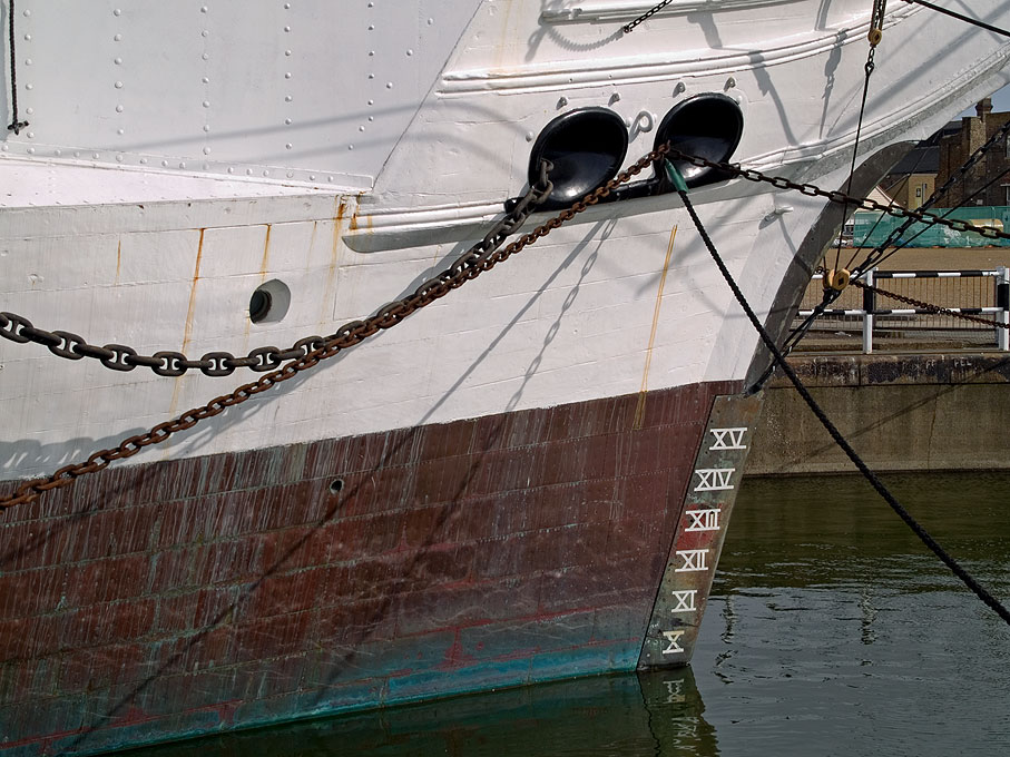
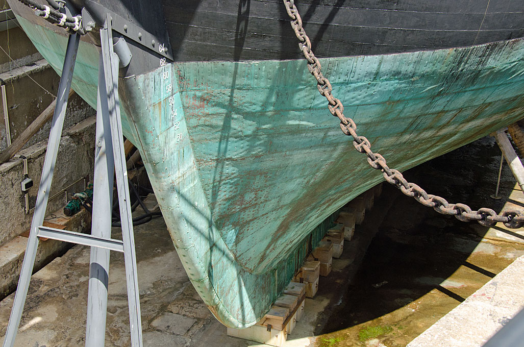
Yes, the copper seems attain this dull reddish-brown colour under water. Another example here from HMS GANNET: The greenish colour seems to be more in the area of changing exposure. I don't have a picture at hand, but on ships taken out of the water, the dull reddish-brown colour of oxidised copper seems to extend over the bottom. However, it also depends on the environment in which the ship is kept. HMS GANNET is in a dock of Chatham dockyard and I don't know how saline the water is - the salinity would change during the tides, as it is located at an estuary. Unfortunately, there are not too many operational ships with coppered bottoms around anymore, so that one can have look, how the operational environment effects the appearance of the bottom. I remember having seen the 'Stockholm Briggen' (a replica built some years ago), laid up for winter in Stockholm harbour and as she was riding quite high, one could see that the waterline was marked by a green-greyish corrosion layer, while the copper above and below had this dull reddish-brown colour. However, the salinity of the Baltic in Stockholm is quite low. To the contrary this is what happens when a coppered ship sits in a dry-dock for a few years: As the Fragata DON FERNANDO II E GLÒRIA had been moored off Lisbon in the Tagus river before beeing restored, perhaps one can find some pictures that show her bottom, when she was taken out of the water. However, this would again reflect what happens to the copper in a brackish environment and when stationary. BTW, CUTTY SARK's bottom is covered in Muntz-Metal rather than copper.
-
I agree with Allan, that you did a pretty good job at the coppering as such! The question now is, what material did you actually use? This would determine how to repair it short of stripping and re-doing it. The flaking you observe means, that the bond between the 'copper' layer and the backing is failing. Now, whatever you will put on that, be it paint or metal leaf, will come off again, as this bond seems to fail. So that needs to be investigated firs. I have to disagree with Allan over the colour of ageing coppering. The green colour one sees on old coppered roofs is due to copper-sulfates, where the sulfur is derived from the sulfur contained in coal fumes and the likes. Seawater contains sulfate, but it appears that the copper immersed into seawater is rather first oxidise. It forms a very thin reddish-brownish oxide layer that 'passivates' the copper and protects it from turning into copper-sulfate. In the area between wind and water, however, the copper-sulfates may form. This, at least, seems to be my experience. Some ships have been sheathed in Muntz-Metal, which is a copper alloy close to brass, but contains proportionally more copper. One has to check on the Internet, but I think it has not been available before middle of the 19th century, so may not be appropriate for your ship. If you can satisfy yourself, you could try to touch up the areas that have lost the coppering with some rub-on copper paint and then give the whole underwater body a washing in dilute brown paint to blend in those areas. I first would experiment with that off model, of course.
-
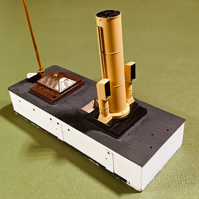
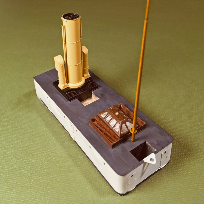
Funnel and Boiler-Room Ventilators Not really much to write about, as the parts had been built quite a while ago. Just a bit of assembly work and painting. Unfortunately, I forgot to take a picture of the assembled parts before painting. Just before painting, also the turning handles for the ventilators were glued on using shellac. These are made from 0.1 mm wire flattened at the ends using a specially made die in my little jewelling press. They are extremely delicate. The colour of the funnel and the boiler-ventilators may be debatable. Research on possible colours arrived at nothing. The 1874 ordinance states that funnels should be ‘yellow’ or ‘mast-colour’, but I could not establish what this yellow actually looked like. A colleague recently discovered an 1890 ordinance that specified that the ‘mast-colour’ should be mixed from 460 g dry white-lead and 260 g dry light ochre pigment with 300 g varnish, to be diluted for application with a further 310 g of varnish. The ratio between white-lead and light ochre suggests a rather light yellow hue, but we do not have a real clue to its actual hue. Circumstantial evidence, such as paintings, seems to suggest that in those early years of the Imperial Navy the yellow was indeed lighter than in later years. Preserved models from the later 1880s show a darker and murkier yellow than one might expect from the above recipe, while the strong yellow of the late tropical livery of the Imperial Navy had a decidedly orange tint. The buff/yellow of the RN seems to have undergone a similar development, while the French navy used a rather murky beige. The first photograph of S.M.S. WESPE of 1876 must have been taken either on a wet collodium or on a dry gelatine plate. Both of which have little red sensitiveness and, therefore, represent colours at the ‘warm’ end of the visible spectrum darker than one would expect from an panochromatic film. The funnel thus appears considerably darker than the white of superstructure. After some colour testing, I finally decided on Vallejo Model Air 71.107 ‘US interior yellow’. Bow view of the assembly of funnel and boiler-room ventilators The boiler-room ventilators show the same level of grey as the funnel and are decidedly darker than the other ventilators. This indicates that they were also painted yellow, while the 1874 ordinance prescribed white for ventilators. Given their closeness to the funnel it does make aesthetic sense to have them painted yellow. Another issue is the interior colour of the ventilators. We seem to take it for granted that ventilators are red inside mostly, but it is not clear when and how this fashion came about. Perhaps they were painted red to resemble the copper that was frequently used in their manufacture in earlier years? On the early photograph the interiors appear very dark, but due to the limited red-sensitivity this is not conclusive evidence that they may have been painted black. Nevertheless, in the end I decided on black for the interior of all ventilators. Stern view of the assembly of funnel and boiler-room ventilators To be continued ....
- 935 replies
-
- 16
-

-
-
I think you are getting there, Keith! As I say, patience and perseverence are probably the most important tools in our box Concerning very small seizings, it is of course diffiult to reproduce them at very small scales, but one can fake them using some very soft thread that is not twisted together. Over here in Europe, one can find such thread in the sewing department, where it is sold for repairing ladies' stockings - but it becomes harder to get by, as few women seem to bother with repairing them. Another source are shops that cater for the fly-fishing fraternity and that may be a more realistic proposition in North America. You only take one or two turns around the shrouds etc. and then go around the middle and make a knot in the back, so that it is not really visible.
-
I like to build 'nice' machines ... but these extruded profiles have become quite easily accessible in small quantities. I also bought some 4 mm shafts a while ago - the idea is to be able to use the hooks and cheap collet-holding chucks from my 'third hand'. I have to see what other suitable materials I have in stock. Something I learned from playing around with the Märkline machine was that it is better to put the crank (I am not intending to motorise it for the time being) onto the connecting shaft, rather than onto to the short shaft with the hooks. If you do the latter, the driving force to the left side has to go through two connections, namely the gear wheels on the right and the left - in the former case you drive both sides symmetrically from the same connecting shaft. Seems to work better. I don't understand, why the commercial serving machines are built so 'lofty'. OK, you may want to have some some clearance around the material to be served so that you can pass a reel with yarn around or have space for the traveller with yarn (see archjofo's building log), but the commercial ones appear to be excessively spidery. I will keep mine low and compact, as the very thin material I will be using may not support the weight of a traveller.
-
There seems to be a collector scene for almost everything, but these Märklin sets and parts have been so ubiquitous, that prices are quite low. When we had to clear out my parent's house four, five years ago, when my mother (97) moved to a retirement home, I checked on the value of a lot of stuff - whether it was worthwhile selling off separately or leave it to the house-clearance guys we had to use. Märklin/Meccano and Lego are two different things and train different skills in children, but as Lego seems to have become more and more 'technical' (after my time - I still remember, when wheel units were introduced around 1962), it probably did kill the market for the others, which where much more expensive to produce. I remember seeing Lego as a kid as something to build houses and such stuff and Märklin/Meccano as something to construct machines and engineering structures, which is what they originally were meant for. Anyway, the Märklin/Meccano route does not have any advantages apart from prototype, proof-of-concept construction. Originally toyed with the idea of making an all-Bakelite machine (sort of replicating 1920s/1930s style of engineering) and bought some thick material, but I don't have a big enough table saw, that can cope with 6 mm Bakelite. I probably go for an extruded aluminium profile backbone with T-slots, which has several advantages. I also considered making the gears myself, I do have a M 0.5 hob, but perhaps that's too much effort for such a tool and would delay completing WESPE even further ...
-
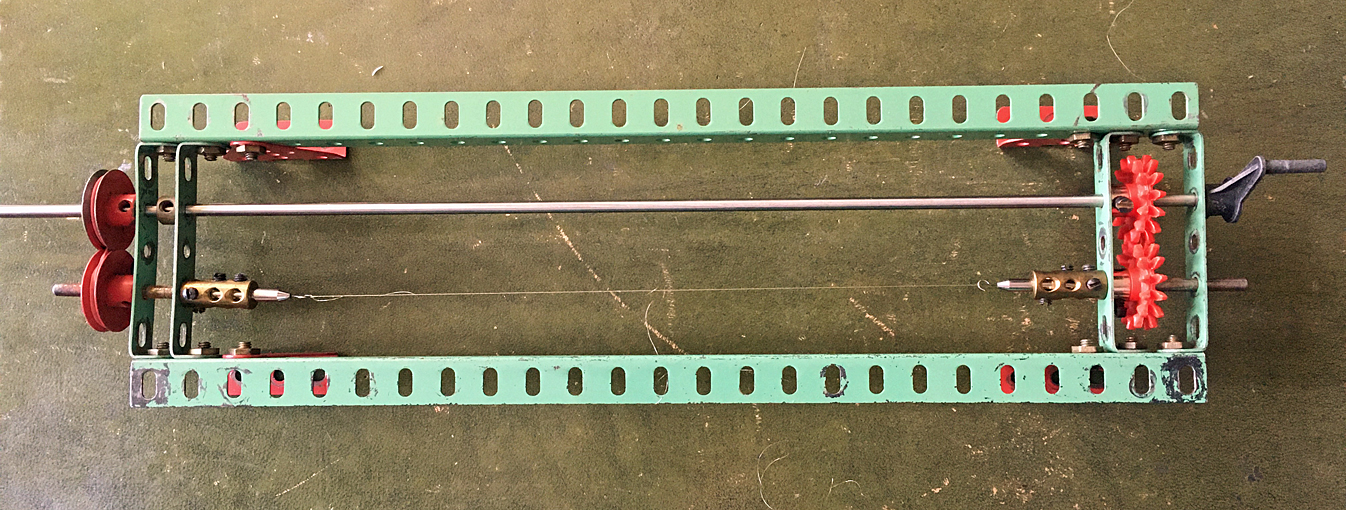
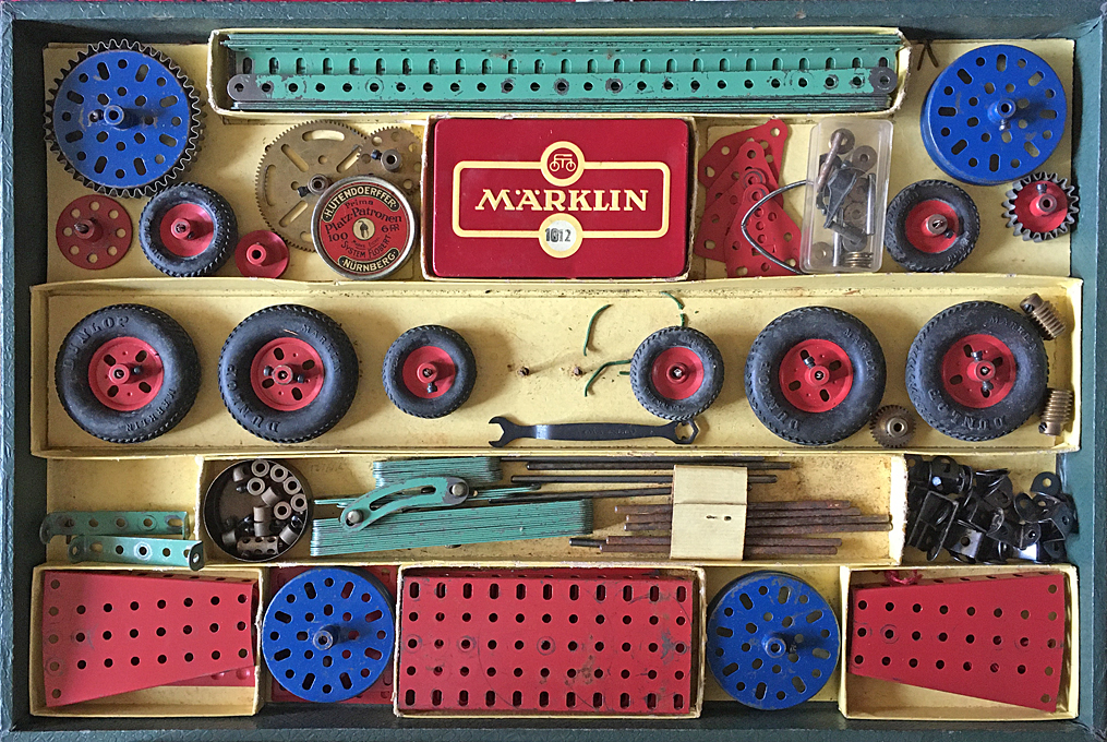
Thanks again for your kind consideration ! ************************************ Interlude: Serving machine On this model there is very limited rigging, four simple shrouds to the mast and the funnel stays. For the latter I have not come to the final conclusion, whether they may have been chain or wire. In any case there would be no serving on them, except perhaps the eyes, in case they were wire. The mast shrouds almost certainly were wire in 1876 on a ship like this. Judging by the available photograph, they were put over the mast with eyes, which is why the mast was prepared as discussed in the previous post. Where wire shrouds go over the mast, they would be served to prevent chafing and cutting-in. As the mast does not carry any sail, the shrouds do not need to be very heavy, 16 mm diameter, i.e., 0.1 mm on the model would be sufficient, as they are also only around 16 m long. The plan is to fashion them from six strands of 0.007 mm silver wire (as apparently used to repair mobile phones and therefore readily available on ebay et al.). They would be made in pairs, looping over the mast from opposite sides and with a seizing to form the eye. The serving required would be about 10 mm long. Medium-sized Märklin construction set of ca. 1960 Given this small amount of serving needed, plus perhaps a couple of block strops, I thought I would get away for the time being with a makeshift serving machine. I kept my childhood Märklin construction set (the German equivalent of Meccano) for such ‘emergencies’ and proceeded to knock up a serving machine with it. Makeshift serving machine made from Märklin parts Unfortunately, it turned out that I only two gears of the same size, while for a serving machine one needs two pairs with the same module and tooth count, so that they have the same distance of the shafts. I had to use two V-grooved wheels with a crossed rubber belt instead. I first twisted the six strands of wire together to form the wire ‘rope’ by uncoupling the drive on the left and then started to wind a 0.05 mm wire around it. While the machine worked in principle, due to the improvised drive-train on the right and the absence of proper shaft bearings, it turned only in jerks and did not run smoothly. While it was a prove of concept, that one can actually serve a 0.1 mm wire rope with say 0.007 mm wire (the thinnest I can get), it requires a precision machine to handle the very delicate material. I had planned to postpone the construction of a proper serving machine until S.M.S. WESPE is finally completed, but will have to look into it now. The ideas are there, but I have to order the necessary materials first. To be continued ....
- 935 replies
-
- 11
-
-
Nice blockmaking - I agree that sometimes the old, traditional methods and techniques turn out to be the best. I did a lot of experimentation on this and then basically came back to something similar as described already 50, 60 years ago in modelling textbooks. I like the idea of the half-round sanding jig ! There are leather-splitting tools on ebay et al. (there must be thousands of craftsmen in China and India, so there is apparently a huge market for specialist tools like this), but Johann (archjofo) indeed made his own to produce leather only a few tens of milimeters thick.
-
Nice brass work! I hope your rail stays put on the mast. I would be a bit worried about differential thermal expansion of the metal and the wood, and about knocking it off by accident. Perhaps glueing it into a slot in the mast would have been more secure?
- 153 replies
-
- 4
-
-
- Ancre
- Bruno Orsel
- (and 2 more)
-
I gather one would need to know what kind of ship we are looking at, also whether it was commercial or naval. Rot would be probably less an issue, but splitting under strain or other damage. On small commercial vessels that operated on low margins, there would have probably not enough money around to pay for fancy metal cappings ... On museum pieces and historic ships I have anything, from nothing to fabricated sheet metal caps to cast bronze caps. However, I have not seen any leather caps and would doubt that it would work - the ropes would quickly tear the leather to pieces, I think.
- 1 reply
-
- 1
-
