


wefalck
-
Posts
6,668 -
Joined
-
Last visited
Content Type
Profiles
Forums
Gallery
Events
Everything posted by wefalck
-
 Brian, see above. Surprisingly, I only lost one of them, when installing them. Actually the steel is a bit of a pain, as I cannot get my tweezers properly demagnetised (I have a demagnetiser as used by watchmakers, but it doesn't seem to work too well ...) and this tiny parts hold on to them, sometimes without me noticing. Actually, the wood effect is just brought about by applying the darker wash unevenly and in the direction of the supposed wood-grain. Also, one has to choose the right colours and work with glazings and varnishes to give the material 'depth', i.e. the impression of being varnished or oiled. Imitation of wood by painting once was a popular technique in interior decoration - to turn cheap woods into something looking more expensive, when for structural strength reasons other materials had to be chosen, or when wood was too expensive, e.g. for panelling walls. There are antique and modern text books on the subject.
 -
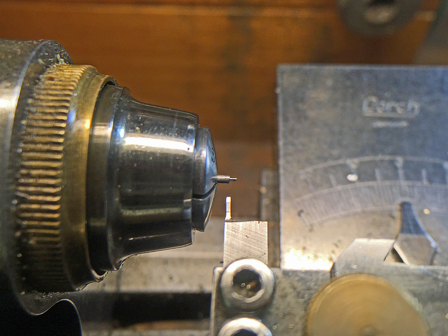
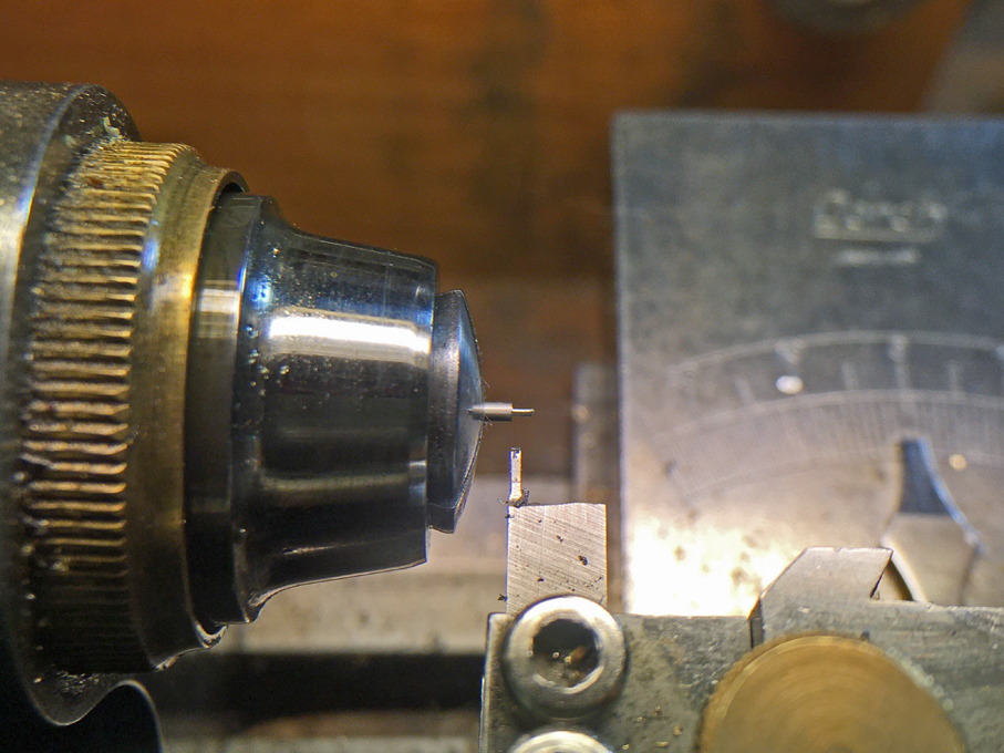
Caution, not too high spindle-speed, veery low infeed and ... a matchbox underneath to catch the part (visible on the last photograph). It is also important to wipe off all swarf before proceeding with the last cut, because the swarf can catch the part on the cutting tool or make it spin around with the stock. Also, one has to learn to live with losses, but in this case surprisingly, I did not loose any at this step. Later on, I lost one finished pin when trying to insert them, that flew across the bench, but I heard it dropping and found it again - only to jump off the tweezers again into some unidentified black hole on the bench
-
Thanks, gentlemen ! Keith, it sounds indeed logic to begin with the step-wise turning at the thinnest end, the shaft. This, however, would leave you with rounding the head of handle in a different set-up. While this is quite feasible for diameters above say 0.4 mm (and I have done it), it is very likely that the handle would just shear off when you try to do this with shaft of 0.2 mm diameter - and I do actually have one of the rare 0.2 mm collets. So shaping the handle first was a much surer procedure and slipping with the files was inconsequential, while in the other case one may have just snapped off the handle. Also, plunging into the material at 0.2 mm cutting width seems to have excerted less forces onto the part than taking side cuts towards the collet.
-
Search for AlexBaronov and Imperial Yacht. The process is galvanoplastic, which has been used for some 150 years to duplicate objects. Alex uses a sort of inverse lost-wax casting. The core is CNC-milled from jeweller wax and then coated in a conductive paint. On this copper is deposited electrolytically to a sufficient thickness. The core is simply melted out. Another technique used is metal spinning.
-
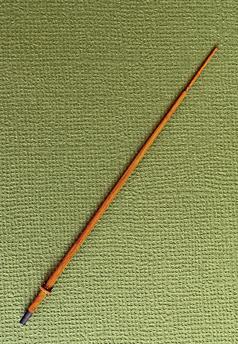
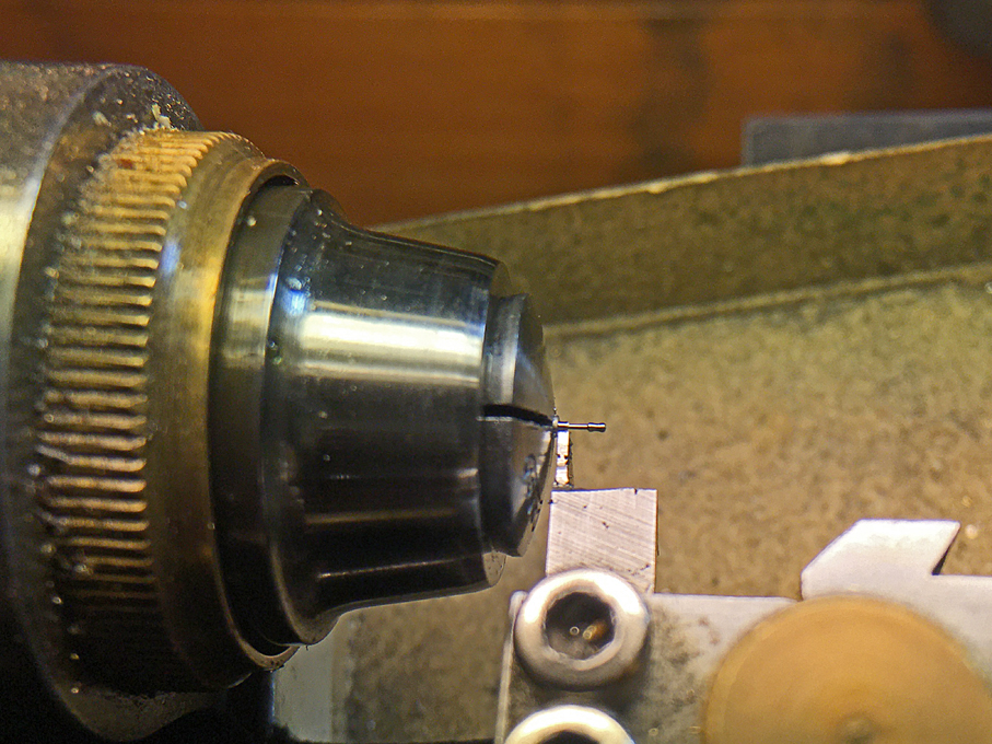
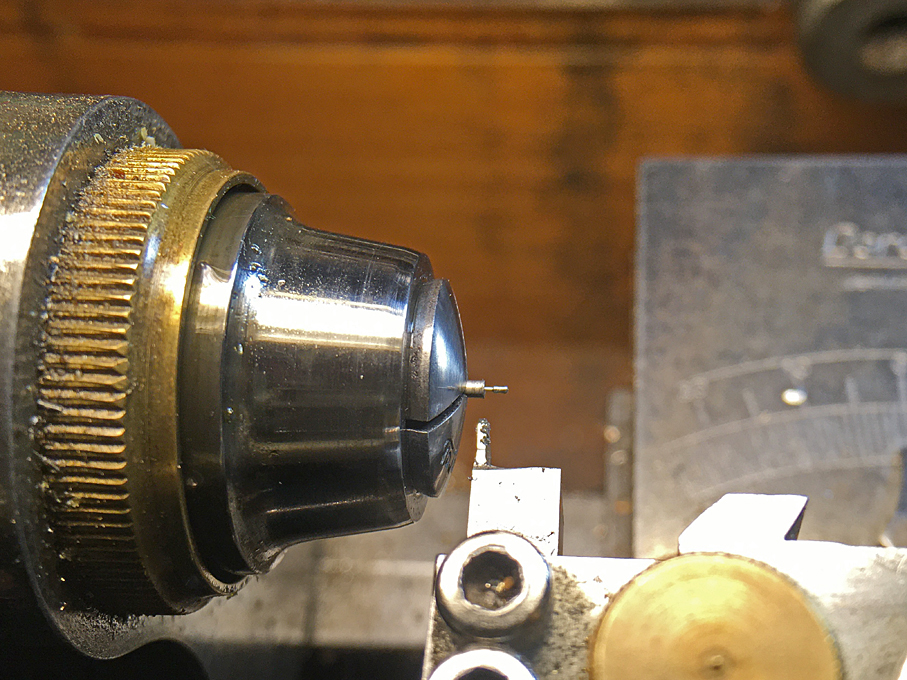
The Mast These boats initially had a very simple one-piece mast for signalling purposes. At a later stage, a more complex version with a topgallant mast and cross-tree was installed to allow for a better spread of signal flags and the cones that indicated the rudder direction to facilitate flotilla manoeuvres. However, the model will be fitted with the simple mast only. The mast itself was turned from a 1.5 mm steel-rod with a shoulder to accommodate the four shrouds and hangers for the signal halliard blocks. The information is rather scarce with only the earliest picture of S.M.S. WESPE showing the whole mast and the lithographs showing the lower part. The height had to be estimated from the photograph, while the lower diameter could be taken from the lithograph. The belaying pins for the signal halliards are set into a wooden shelf, rather than into the spider band. This wooden shelf was fashioned from a tiny piece of bakelite paper into which the appropriate holes were drilled before. Belaying pins of 2 mm length and 0.2 diameter are a modelling challenge. A first attempt using lengths of wire and drops of white glue to represent the handles did not produce consistent and satisfactory result. Therefore, I decided to attempt to make them the ‘proper’ way, i.e. to turn them. After a couple of failures (though the first two attempts went well), I arrived at a procedure that produced consistent results with a low failure rate. The key is to do the turning in small steps to minise cutting forces, having a sharp tool, set to just a tad below centre-height. The material used was 1 mm mild steel-rod because the brass I have available would have been far too soft for such tiny pieces. Although the belaying pins are a bit oversized for flag-halliards, making the pins was a bit of a proof of concept with my follow-on project in mind, where I will need quite a number of such small ones. In a first step, the 1 mm diameter was reduced to 0.4 mm over a distance of 0.8 mm. 1st step in turning micro-belaying pins: roughing out the handle The handle then was shaped using a 1 mm mouse-tail and a tiny flat file: 2nd step in turning micro-belaying pins: shaping the handle with files Then the diameter below the handle was cautiously reduced to 0.2 mm. The first cut here is quite critical, as the square cutting tool cuts over its whole width of 0.4 mm. 3rd step in turning micro-belaying pins: reducing the diameter of the shaft to 0.2 mm In several 0.2 mm steps one then works towards the target length of 2 mm. Final step in turning micro-belaying pins: reducing the rest of the shaft to a diameter of 0.2 mm When trying to reduce the diameter below 0.2 mm, the finished belaying pin usually shears of cleanly from the stock. The pins then were chemically blackened. The mast was given a base-coat of Vallejo 71.033 Yellow Ochre, a wash of Schmincke 28610 Ochre, and a very light glazing of Vallejo 70.956 Clear Orange. Once the blackened belaying-pins had been inserted the whole assembly was given a light coat of a mixture of Vallejo satin and gloss varnish to make the mast resemble oiled wood. The shoulder, were the shrouds rest probably had been protected by a copper sheathing and this was imitated by paint. The finished mast The shrouds were probably made from galvanized steel rope and need to be served in the area where they attach to the mast. I still have to work out a good way to imitate this in 1:160 scale and probably need to build the serving machine first that I had planned to make for a long time. To be continued ....
- 935 replies
-
- 14
-

-

-
Over here in continental Europe these 'informal' aspects of our industrial history and heritage seem to be largely forgotten. At least there seems to be a lot less published material about it.
-
Is that going to be the radiator-cover for a car engine ? Mounted on a railway carriage ? Did you do the tapping on the lathe ? 🤔
-
On many such boats, they would have had a windlass somewhere behind the mast, which would also serve to raise the anchor. However, having the windlass in the bows would also be possible, but one would need a block seized to somewhere near the foot of the mast to redirect the halyard to it, if a sheave in the mast is to be used. This publication of the Maritime Museum in Gdansk you mentioned is only available in Polish, I suppose ?
- 17 replies
-
- 3
-
-
- Vistula barge
- card
- (and 1 more)
-
Indeed, it would have been highly doubtful practice to leave such barrels on deck to be broken up by overcoming seas. Without salt, you may as well sail home. The only barrel/cask that was often stored on deck, securely fastened in chocks and with lashings, was that for a few days worth of drinking water from which the crew and the kitchen drew. It would be placed in a reasonably protected area.
-
I suppose this is a sweep, rather than a rudder. The Vistula/Weichsel is a rather slow flowing river and such boats mainly drifted down-river, so one needed a lot of fulcrum to steer them.
- 17 replies
-
- 4
-
-
- Vistula barge
- card
- (and 1 more)
-
Gütermann (https://www.guetermann.com) is a German manufacturer, so you could write to them and ask them through which channels they sell their products in Portugal. Otherwise, you might find an ebay trader in Portugal or somewhere else in the EU, where postage is not so prohibitive.
-
Silkspan can be to different things, depending on which side of the Atlantic you are: either thin 'Japan'-paper or a very light silk fabric. In both cases it takes its name from the use as covering for model airplane wings. It is glued on with cellulose glue, when wetted it 'spans' itself over the wing frames. The effect is enhance by a specic kind of varnish that shrinks it on in addition. I also would use a piece of paper appropriately painted to resemble greased leather.
-
Steamboats and other rivercraft - general discussion
wefalck replied to Cathead's topic in Nautical/Naval History
I just chanced again upon the posts on the Missouri- and Missisipi-Flatboats. Somehow they sparked my imagination as a boy, but I don't remember in what context. Perhaps based on an account of the Lewis and Clark expedition. I remeber making a drawing of one at school. These kind of one-way craft occurred also on various European rivers that originated in wood-rich areas, most notably the Danube. The city of Ulm was one place at which they were built in large numbers and used for transporting goods and passangers down-river, sometimes reaching the Danube Delta. Most, however, only went as far as Vienna and Budapest, where they were broken up and sold as construction material. The ones built in Ulm were called 'Ulm Box' in the 19th century and painted in the city colours black and white with a kind of zebra-pattern outside: Historical image from Wikipedia From https://deutsche-gemeinschaft.eu/de/geschichte/#iLightbox[bf3bdc6c58c6d1ab60e]/0 At times they also transported groups of German emigrants that settled in areas de-peopled during the Osman expansion into Europe after they had been retaken. These German groups retained their cultural traditions and language in modern Hungary and Romania for instance, but also migrated further east into what is now Ukraine and Russia. The boats were steered downriver with two pairs of long sweeps, similar to the timber-rafts with which they shared the river und which also transported goods and passengers. The crews of both, the Ulm Boxes and the rafts walked back to Germany from Vienna and the Balkans in the days before there was a steamboat service. The Ulm Boxes actually followed a regular weekly schedule until steam took over.- 281 replies
-
- 5
-
-

-
- Steamboats
- riverboats
- (and 3 more)
-
ELBE 5 was built from wood by the H.C. Stülcken yard in Hamburg. Being built from wood may have been her luck in 2019, when due to a seamanship error she was overrun on the Elbe river by a small container ship. She could be salvaged and underwent restauration. Not sure whether this is completed yet. Why did you use the rather odd scale of 1:51 ?
- 180 replies
-
- 2
-
-
- pilot boat
- Elbe 5
- (and 3 more)
-
Air brush vs paint & brush
wefalck replied to jefferyt's topic in Painting, finishing and weathering products and techniques
I have been spray-painting now since the early 1980s, though for me it is a rather intermittent activity that comes close to the end of a building project and I certainly do not have that many hours of experience under my belt as many colleagues from the plastic fraternity. When diluting acrylic paint, one has to be sure, as whith other paints, that the chosen solvent does not disturb the paint formulation. Acrylics are dispersions and dispersions are prone to breakdown and coagulation, if the wrong solvent is used. So not all acrylics can be thinned with alcohol. As my projects are small size-wise I do not need large quantities of paint and in fact am still working from most of the bottles that I originally purchased. I prefer acrylics diluted ready for airbrushing. You pay a lot for cheap solvent, but you are sure that you get the right consistency and do not have to worry too much about shaking up the paint well enough. Diluting acrylics from a tube is a pain, has to be done very carefully, and therefore takes a long time. Also, in order to work well, the quantities of paint used cannot be too small, leading to waste. I found that homemade dilutions are not as stable, as the factory ones. As I don't have a spray-booth with extraction fan, I do not use paints with organic solvents in the airbrush. Also, cleaning of acrylics is much easier as it involves only water and you do not need to manage waste solvents. Normally, I only use the airbrush for a few minutes at a time and then immediately proceed to clean it under running water, dismantling it as much as is possible without tools. This really takes only five minutes or so. Also make sure that paint never dries in any boreholes, as it is difficult to remove from there. -
Looking forward to how you will be treating the framing in the stern. I find that always a bit of challenge.
-
Actually, the thingy doesn't really tie the knot, you do this separately. All it does, it keeps the knot close to the pearl in this case. You can do this perhaps even more easily with a needle held in a pin-vise around which you make the knot - pull on the loose end until the knot sits close to point were you want to have it and slowly pull out the needle while still pushing it against the pearl or whatever.
-
Wasn't there a report on the voyage of U.S.S. PEACOCK printed ? I vaguely remember that there was a chapter on polynesian seafaring, but I could also mix this up with another ship. Also the Bernice P. Bishop Museum (https://www.bishopmuseum.org) may have some information.
-
In my understanding a 'knot' is within a rope or between two rope ends, while a 'hitch' is a 'knot' used to secure a rope to an object. In German we make similar distinctions.
-
Yes, I took those for granted ...
-
I am actually sometimes wondering, whether kits do not make the task of building too daunting. If well designed, everything should fall into its place, but you really have to be able to follow the ideas of the designers in addition to understand the ship itself. That's a double task.
-
How is this supposed to work ? Whatever the intended way of use, I cannot see it being used 'on board' of a model, where you would often need to reach deep between different other parts of the rigging. BTW, the amount of knot-making on a model is often overestimated. There are very few places where 'knots' actually are needed (attaching sheets to sails comes to my mind, for instance). In most cases eye-splices, seizings or lashings are used (which may be indeed finished off in a knot). Belaying is a form of knot-making, but not really.
