


wefalck
-
Posts
6,664 -
Joined
-
Last visited
Content Type
Profiles
Forums
Gallery
Events
Everything posted by wefalck
-
 This is definitely not a carronade. However, it may be that the photograph was distorted by the book-producers to fit the available space. The carriage looks rather low. Early carronades were mounted on normal trucked carriages. Also half-trucked carriages were used sometimes, I think in particular in France. But then quickly the slide carriages became common for them.
 -
On the sheaves vs. blocks question: I have the feeling that the sheaves went out of fashion in the later 19th and were replaced by blocks bolted to the deck. The idea is turn the run of the rope by 90°, so that more men could work on it. If you pull straight down on a rope you can use your whole weight, but you could have only two men working the rope. Blocks were commercial items by then that would be mass-produced, while a bitt with sheaves would have to be made by the shipyard and would have been more expensive. Also, the sheave-holes weaken the bitts.
-
Mostly, carronades were used as broad-side guns, whose carriage was pivoted at the front. However, the sliding carriage could also be designed with a pivot in the centre, so that it could be rotated through a full circle, when mounted on the centre-line of a ship. I gather that this what is meant. However, I doubt that using a carronade is a good proposition for this. Carronades are short-range guns and as such would have a considerable muzzle blast, which could blow away bulwarks and damage the deck-planking. Normally, long guns were used in such positions.
-
I am not sure, whether she would have had a coppered bottom during her professional life. Today, due to the penetration of terredo navalis through the Channel into the North Sea, she certainly will need protection though her berth is in brackish water, in the Elbe estuary.
-
I didn't realise that this would be a clinker-built. Nice job ! Did you chase the upper edges of the lower planks to allow the following strake to run into the stem rabbets?
-
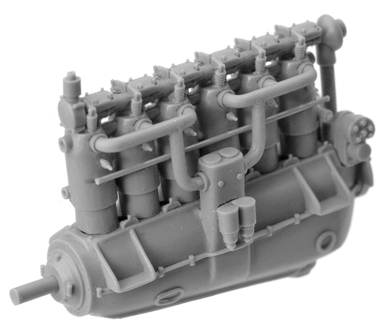
The company that makes them is called Small Stuff: https://www.smallstuffmodels.com/p/products.html#!/1-72-Detail-Sets/c/4286864. However, I just realised that there may be supply disruption due to the war ... Most of the engines are of the radial type, but they also have a couple of others: That's a Mercedes 200 hp one.
-
I think I have seen this strange fore-and-aft arrangement for a steering wheel on some naval launches too. Surely needs a bit of time to get used too - can lead to fatal errors (the pilot-schooner ELBE Nils is building here on the forum was run over by a freighter a few years ago because the amateur helms-man confused putting the helm to starboard with putting the rudder over to starboard ...). Since I saw these beautiful 3D-printed WWI aero-engines available in 1:72 and 1:48 scale I am tempted to make a (free-lance) runabout with one of those - post WWI a lot of these became surplus and were used in speedboats.
-
If have been to the yard, where they built (S.M.S.) GRAF GOETZEN for the lake ... Coming back to the problem in hand: an option would be to roughly cut the disc from 0.5 mm brass sheet and then use what the watchmakers would call a wax- or a cement-chuck - You take a piece of round bar, doesn't matter what metal, chuck up in your three-jaw chuck and then face it off flat; to this you cement your roughly cut brass disc using CA or shellac and turn the outside and the grooves ...
-
As you have a lathe, why don't you simply turn them from brass or acrylic stock. They will have to be painted black anyway, I suppose. They look varied a bit, but they often had shallow concentric grooves as an anti-slip feature and typically to sunk-in handles give a fulcrum to turn them - they were locked with a sort fo bayonett-lock into a circular cast-iron frame in the deck.
-
Line drawing and art - Willem van de Velde son
wefalck replied to Aa-schipper's topic in Nautical/Naval History
I was quoting from memory and my memory sometimes is not the best anymore ... so obviously I only scored a near hit. As to the violin: these were used, inter alia, as 'party boats', so not surprising that there would be also some musical entertainment. -
A 'standing' gaff does not mean that it cannot be lowered. It means it is not normally lowered to make fast the sail. Standing gaff sails were typically fitted with three brails that allows it to be gathered up towards the gaff and the mast. Of course, when reefing, you would lower the gaff. Towards the end of commercial sail and on some steamers there were real 'standing' gaffs and the sails were attached to them with a rail and runners, very much like our curtains, so that they could be gathered up to the mast. It seems that on the British Islands the luff was mostly hooped to the mast, while on the continent and on the other side of the Big Pond lacing was more common, particularly also for smaller boats. Similarly, in Britain gaff sails were only fixed with their clew to the boom, while in the USA they were mostly laced. In the last decades of sail, lacing became more common everywhere. When reefing a loose-footed gaff sail it is not tied down onto the boom, but to itself, in the same way as you would reef a stay-sail or a boom-less gaff fore-sail. If you want to read-up on handling gaff-sails, I would recommend John Leather's 'Gaff Rig', though he is a bit biased towards yachting practice.
-
Line drawing and art - Willem van de Velde son
wefalck replied to Aa-schipper's topic in Nautical/Naval History
Didn’t Ab Hoving built a model after this drawing? -
Hhm, I don't think that this was such a good idea to put the sanding filler onto the wood before glueing - in this way the contact cement cannot key into the wood very well anymore and the solvent from the cement has nowhere to go to ... hope your copper sheathing will stick in the longer term
- 180 replies
-
- 1
-

-
- pilot boat
- Elbe 5
- (and 3 more)
-
That's what I would have thought. It's quite fascinating to see such a schooner being operated by a well-trained crew - around 2000 I was sailing in the British Virgin Islands, when in one of the little ports we stayed one of them arrived at dusk under sail, bearing up to the jetty with precision and taking down the canvass in a matter of seconds literally and making fast. Unfortunately, the next morning, when I wanted to check-up on her, she was already gone again. I finally got around to really read John Leather's 'Gaff Rig' and he write quite a bit about the crews of these pre-1930s yachts, their professional crews and captains, many if not most of which in Europe were fishermen from SE England. They fished in the winter and manned the yachts for racing in the summer.
-
... takes up a lot of space! I wonder how it would affect the sailing, as it is probably quite a deck-load.
-
And no one imagines how much work goes even into such mundane pieces of equipment ... The launch is quite big, where is it actually stowed on board?
-
I just had a look at the images that I had collected for my series of articles in our quarterly DAS LOGBUCH and there are one or two photographs taken by Gutstav Caillebotte's brother that show a Clipper reasonably close and it looks indeed that they used small deadeyes ...
- 153 replies
-
- 4
-
-
- Ancre
- Bruno Orsel
- (and 2 more)
-
Thanks, gentlemen! @Keith Black I don't have a time-plan, it takes as long as it takes. Making and in particular installing the boat will be another challenge ahead, as this arrangement will be very flimsy. @starlight to your questions: - sorry for loose use of terminology, yes they are the same - sometimes my mother-tongue confuses me also, as it is 'Vordeck' in German ... - as said in an earlier post, the idea behind the planking pattern seems to have been to arrange the seams in the direction of the gun-blast to reduce the risk of damage; the muzzle is quite low above the deck. - I do have information what kind of decking material was used by the Navy in principle, but I don't know what was used on this particular class of boats; teak was expensive, but makes sense on this exposed deck; perhaps I should have changed the decking in the barbette to this improved paint scheme, but I don't want to rip it out again and repainting in the confined space will also result in a lot of collateral damage - I tacitly assume that it may have been another species of wood; once the gun has been installed, it will also be much less visible.
-
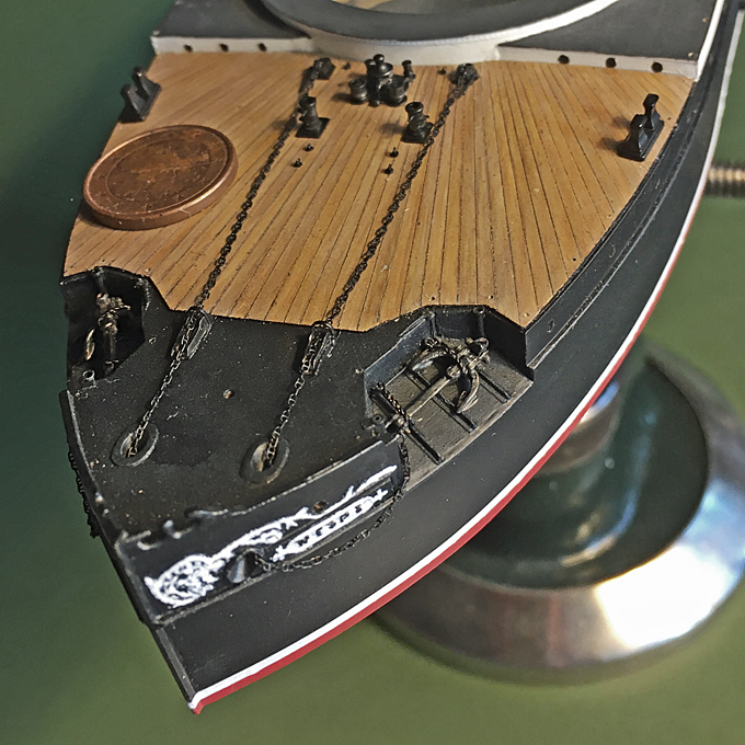
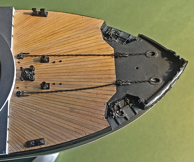
Thanks, gentlemen, for your continued moral support! ********************************************** Quarter-deck – further work Having now satisfactory wooden decking for the quarter-deck, this was permanently cemented into place, allowing to progress with the installation of the various bits and pieces that had been fabricated years ago. These include the anchor capstan, the four patent chain-stoppers, chain-bollards (which are hollow and double as a base for the crew accommodation ventilators), various eye-bolts to which stoppers are shackled, that secure the chains during mooring, and the forward pair of mooring bollards. Populated quarter-deck Probably the only bought-in item will the studded anchor-chain. Recently, some really good 3D-printed chains have become available. My excuse is that that many shipyards did not make the chains themselves either, but bought them from specialised forgeries (apart from the fact that I didn’t want to go insane over making such microscopic studded chains). I choose the smallest size from yxmodels (Product no. YXN700-001). With 8€ plus shipping for a length of 120 mm they are the most expensive (not considering my time) item on board. They are printed in a light brown resin and were given several light dusts with acrylic paint to turn them black without clogging up or cementing the links together. The connecting link with the anchor shackle was bent from 0.2 mm tinned copper wire. The anchors are held in place with chains attached to the release gear that had already been installed. These chains were imitated by twisting together two strands of 0.1 mm blackened copper wire so that each twist is about the length of the assumed link length. The length of twisted wire then was folded over in half and twisted together in the opposite sense. With some imagination this looks quite like a slightly twisted chain. The anchor were secured in place with a couple of dots of shellack and then release chains installed – which not unexpectedly was a really fiddly task. I arranged the chains as they would be kept ready for dropping the anchor or in light weather, without further securing by rope chain-stoppers, as I do not have any pictorial evidence for how that would have been done on the real ship. The quarter-deck later will receive some light weathering and the chain-rails need to be installed, but as they are extremely fragile, this will be put off to the moment, when the model is installed on its final base-plate. Populated quarter-deck To be continued ....
- 935 replies
-
- 25
-

-
-
That's a clever drilling jig for the deadeyes 👍 I am actually quite surprised that such kind of boat still uses deadeyes. Given the quite close connection that the French yachtsmen had with those in the USA, I would have thought, that screws might have been used already. Or hearts and lanyards. Deadeyes look rather 'rustic' on such a boat.
- 153 replies
-
- 4
-
-
- Ancre
- Bruno Orsel
- (and 2 more)
-
Waterslide Decal Paper
wefalck replied to hof00's topic in Painting, finishing and weathering products and techniques
How did you do the colour-matching, by trial and error with the colour settings in the file? -
Dugout canoe build
wefalck replied to reklein's topic in NAUTICAL RESEARCH GUILD - News & Information
Yep, cultures always scavanged foreign materials and traded them. It is difficult to know what an 'original' culture was and what materials and tools the culture used. The Inuit, for instance, have traded in sawn planks and metal tools from European whalers and settlers for centuries. -
Dugout canoe build
wefalck replied to reklein's topic in NAUTICAL RESEARCH GUILD - News & Information
Makes me nervous, when I see something like this: A boatbuilder on Zanzibar shaping the stem-knee for dhow, photographed in 2012.

-
Waterslide Decal Paper
wefalck replied to hof00's topic in Painting, finishing and weathering products and techniques
Would only work, if you could print exactly the colour you needed. Never works, not even even with black and white. Of course there is white decal paper on the market.
