HOLIDAY DONATION DRIVE - SUPPORT MSW - DO YOUR PART TO KEEP THIS GREAT FORUM GOING! (Only 53 donations so far out of 49,000 members - C'mon guys!)
×


jud
-
Posts
1,171 -
Joined
-
Last visited
Content Type
Profiles
Forums
Gallery
Events
Everything posted by jud
-
 Last time my wife asked me to drill some holes in the bottom of a tub she wanted to use as a planter, I just used my 22 pistol to punch the holes, worked great. She had the same need a few months ago and after watching me, used her own pistol to do it. Might work for you, if not, you will have some fun. jud
 -
Probably the iron on those Hatch Boards is over scale, also every hatch board I have seen had the lifting rings recessed when not in use. Hatch Boards were used to seal up an opening in the deck from the elements and were usually covered with a water proofed hatch cover made of canvas. There should be provisions for a ring or Battens and wedges around these types of hatches, unless it is a fish hold and water getting in did not mater. Grates were used for ventilation and warships using black powder needed a lot of ventilation, merchant ships wanted water tight spaces below decks to protect their cargo, hence the differences in covers. jud
-
Nenad, don't think you are doing so bad building this model, you started out the hard way and have been learning new things all the way, the result so far is a good model with some exceptional detail while becoming an expert on the Cutty. Don't change horses in mid-stream and go faultless on us, that would ruin the trip and the model. Way I heared it was; measure twice and wack it off with an axe. jud
- 4,152 replies
-
- 7
-

-
- cutty sark
- tehnodidakta
- (and 1 more)
-
Little Machine Shop 2" Quick Vise Review
jud replied to jhearl's topic in Modeling tools and Workshop Equipment
Sorry but I think that vice was compared to others on their site as being low cost and easy to use, not a machinist or bench vice, so don't expect it to be more than it is. Believe that vice is intended to be roughly set close by hand. It was never intended to be retracted with the tightening screw, only to snug up and release with the screw. Packed in grease, good, there to protect it from rust in the warehouse and during shipping, ever been issued a rifle and had to clean the cosmoline from it. Cosmoline will gum up the works. That vise is not a precision tool, I have one similar on an older power hack saw, it has a pivoting jaw on the adjustable side, never liked the style, but it works. Looks like you got the vise you payed for, just don't understand how it's intended to be used yet, it's not a bench vise and not a precision tool. A little fine tuning with a file and some emery paper might do wonders for it, perhaps using some soft jaw covers would be all you need. jud -
It's a Boat Boom Nenad. That one will have drop lines for two boats and a rope ladder, usually no steadying hand lines on the boom. Gear going in or out of the boat will be hauled using a line from the deck, not the boom. Stern lines leading aft to the ship are used to hold the boat parallel to the ship. jud
- 4,152 replies
-
- 5
-
-
- cutty sark
- tehnodidakta
- (and 1 more)
-
Thanks Nenad, can't argue with that. The brass hand rails on the inboard side of the ladders would be my choice of style. Little work outside of the Bulwarks, so lifelines would not hinder the working of the ship. jud
- 4,152 replies
-
- 5
-
-
- cutty sark
- tehnodidakta
- (and 1 more)
-
Doubt that those Lifelines with nets were part of the working ship, Probably only there because of young or clumsy visitors. A single grab line on the inboard side of those forward ladders, 'plenty of handholds or bracing points on the outboard side of them', may have been part of the working ship. Those ladders are steep enough to descend when facing away from them as Seamen do, safely, if a grab point is needed, the rails of the ladders are within reach. Placing those nets on your model would be a challenge, keeping them from being damaged if placed now and restricted working space if later, I think you can leave them off without compromising the accuracy of the working vessel. jud
- 4,152 replies
-
- 4
-
-
- cutty sark
- tehnodidakta
- (and 1 more)
-
Seats of ease in the days of sail were located at the bows,'head of the ship'. The seats of ease became known as the Heads. Regardless of location, the afloat facilities for some time are known as Heads. Going to the Head means you are going to relieve yourself and you are going to the Head to do it. Your little cabins are Heads, may be others in Officers Country, they too would be heads. jud
- 4,152 replies
-
- 7
-
-
- cutty sark
- tehnodidakta
- (and 1 more)
-
There seems to have been an unusual gun tub surround on those ships. Can't call them splinter shields because the solid part was only about 2 feet high and a rail above it at about 3 1/2'-4' above the gun tub deck. Suspect the stanchions you have in the photo are for that top rail structure, probably to be reinforced by the lower solid surround. Need that solid surround to keep things, 'like empty brass', in the gun tub that would fall out, without it. jud
- 227 replies
-
- 2
-
-
- BlueJacket Shipcrafters
- Stephen Hopkins
- (and 2 more)
-
Nice looking WC Closet, Nenad. Just keep the door shut so it will look realistic, need some leg room so the door could be closed during occupation if you intend to display with the door open. If so, trim the seat boards back to the rear of the existing seat hole, then make another hole. jud
- 4,152 replies
-
- 5
-
-
- cutty sark
- tehnodidakta
- (and 1 more)
-
Looking good Dashi. jud
-
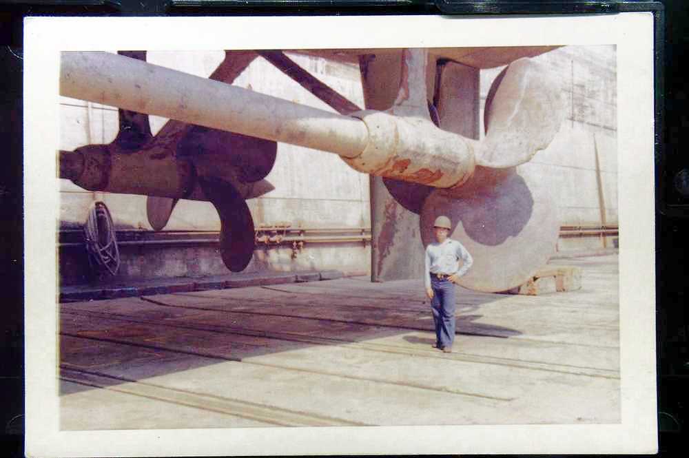
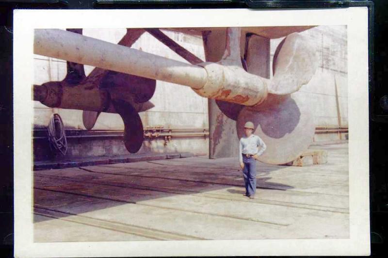
Thought this might interest you. 1960 dry dock photo of the chipped screw after a collision, rudder and shaft brackets were not the focus, but you can see the same type of brackets that you fabricated and placed on your model is almost identical to what was on this Fletcher Destroyer, ' USS Ammen DD 527 '. about the only thing in common with the Arleigh Burke jud ps Me at 17 posing as a scale bar.
- 68 replies
-
- 11
-
-
- Arleigh Burke
- BlueJacket Shipcrafters
- (and 1 more)
-
Thought that the Triple Expansion Steam Engine powered Liberty Ship was replaced by the Steam Turbine powered Victory Ships with 3 Holds forward and 2 aft. There were quite a few Victory Ships steaming around the world in the 60's when I was in the Navy, one was ahead of us Transiting the Panama Canal in 66. jud
- 56 replies
-
- 3
-
-
- sd-14 cargo ship
- card
- (and 1 more)
-
The ships I rode had their accommodation ladder platform hinged to the ship on it's inboard side with chains and slings in place to hold it level when deployed. The ladder itself was hinged to the upper platform and the lower platform was hinged to the ladder so all could be straightened out and turned up to lie against the rail as a unit. There were fittings and clamps in place to secure it all to the rail. Those ladders were used to board or leave the boats when the accommodation ladders were deployed. They were rigged with dedicated slings both top and bottom and could be deployed, recovered and securely stowed quickly. My guess is that the Cutty Sark had accommodation ladders on each side and unlike the ladder in the photo, which looks like an afterthought to me, probably had strong gates in the Bulwarks serving the ladders. As demand for passenger provisions declined with her age, the ladders may have been removed to avoid the maintenance and frequent need to rebuild them. The idea of a large heavy accommodation ladder with its upper and lower platforms being stowed with the boats, is not logical. Merchant ships were a bit conservative with the number of crewmen, they had much more needful things to do than man handle and rig the necessary tackle to move such ladders back and forth. jud
- 4,152 replies
-
- 5
-
-
- cutty sark
- tehnodidakta
- (and 1 more)
-
You have hit the nail on the head about what I have been thinking. We see some good looking rope coming off of those commercial machines but the tension is forced to change along the length of the rope as it laid up. Gravity and an adjustable weight, a free turning spinner on the laid up end, along with a hand held spreader, requiring close attention, would be the more versatile machine. Those commercial machines can make rope that is much better than what is usually provided in most kit's, that and the ability to size the ropes produced is probably the priority for most purchasers of those machines, not a perfectly working rope. Room for both commercial and the home grown variety, which type for you? Depends not only on cost but maybe a little traditional rope production, might be a large part in the choice. jud
-
Why was Mr. Manly in a heap of trouble? Seems to have been stated and affirmed that he left Sick Bay in spite of his bad knee and passed shot and later powder replacing a wounded man. Anyone who has been around work similar to hauling on tackles and the quick movement needed to serve a gun would have known that bad knees would have hindered the working of the gun, causing a slower the rate of fire. A good gun Captain would have kept him away from his gun, I have been a Gun Captain, for training, the duds or healing injured, were second loaders and we didn't fire enough ammo to run short, in combat, didn't want them around. Sounds like a vindictive officer, perhaps the Captains later question might indicate there might have been some earlier intervention, causing a vindictive attitude by an officer, were I on that court, I would have released Mr Manly and chastised the officer responsible for questionable accusations and wasting the courts time. Apparently there was some shirking of duty by hiding that was more worthy of attention than Mr. Manly, with his apparent the day before the battle injury causing him to be held in sick bay, only available for limited duty if sufficient need was there. Also it came out in the testimony that the crew was poorly made up in ability and experience. Testimony also reviled that the crew were in a greatly weakened state caused by winter and probably poor rations. In spite of testimony the state of the crew is probably the greatest cause in the loss of the ship along with poor outfitting. Looks like there could have been a little class warfare going on which the court was attempting to reveal by its questioning, were some attempting to pass some blame to crew members by their testimony, Mr. Manly's conduct was not the cause for losing the ship, it seems that Capt. Wales was supporting Mr. Manly and his conduct with his question about being seen passing powder. . jud
-
DELFT SHIP
jud replied to NavalArchAngel's topic in CAD and 3D Modelling/Drafting Plans with Software
X, Y and Z Coordinates define a point within a Rectangular Coordinate System, sometimes those points are located using a Polar System, direction and distance for the X, Y and adding the vertical angle and slope distance to get the Z, easier to reduce the slope into horizontal and vertical differences. Those who work with Rectangular Coordinate, except for Mathematicians, do so using the NE quadrant so there are no negative numbers or zeros floating around. I have set my LST Rectangular Coordinates up in the NE quadrant. My plans have the profile view from the Starboard side, the plan view in relation to the profile view with the bow to the right, the end views are standard with the bow rearward on the right and the transom forward on the left. Frames are numbered from the bow rearward. These plans use a horizontal base line under what would normal be the keel, being a LST, no keel but a Center line on the skid plate, not a big deal for plans, does effect steering, drift and ride, The decks are parallel to that Base line and the Frames are perpendicular, the bottom is on a slope for beaching. My X coordinates begin with zero being about 108 feet aft of the transom and increase as they move forward, My Y coordinates are along the Center line and the center line coordinates are 100 with offsets based on that, the Y component is not seen from the profile view. The Z coordinates are based on the noted base line and the base line is at 100, that makes a Z component of 114.0000', 14 feet above the base line. Using 2 D software forces me to sometimes use the Y coordinate as an X coordinate and the Z coordinate as a Y coordinate when working from an end view of a frame. Not a problem, easy to deal with and just an inconvenience to properly arrange the numbers for the final 3 D coordinate. The Frames are numbered from the bow but the frame numbers will be shown in the descriptors for each X, Y and Z Coordinate. All set up so each 3 D coordinate will show where along the hull, how far left or right of center line and how far above the Baseline the point is as well as the frame it is an outboard part of. those points will be the control points for contour lines,'waterlines', from which I can extract adjusted and corrected cross sections. jud- 15 replies
-
- 1
-
-
- delft ship
- 3dmodelling
- (and 1 more)
-
soldering iron or torch? advice please
jud replied to Mark Pearse's topic in Metal Work, Soldering and Metal Fittings
Acquired a US Oxy Acetylene mini torch as a gift, it has 5 different brazing or soldering tips. Haven't had the need to use it yet, but checked, it will hook up to either one of my Oxy Acetylene setups and use their regulators. Will need to go to the shop or wheel a set of tanks down to the house to use the mini, if I choose the house, I will probably leave the tanks and regulators outside, unhandy but the risk of acetylene collecting on the floor would be reduced. Acetylene needs watching and good ventilation is a must. In the shop, the doors are usually open, if not there are plenty of openings at floor level to allow heavy gas to get out. This mini torch looks well made and should heat well for soldering or brazing on the properly sized objects. Were it setup with small portable tanks and regulators, I would expect most modelers would prefer it over other heat sources for soldering, the heat is fast and can be concentrated as it is with full scale torches.. jud -
Military.com The birth of the U.S. Navy didn't take place till a few months after the start of the Revolutionary War, and was disbanded shortly after. It wasn't brought back into existence for nearly 20 years, and it wasn't until 1817 that the first official uniforms were created. The War Department officially declared that enlisted sailors wear "blue jackets and trousers, red vest with yellow buttons and a black hat." But, at that time funding was short, so uniform regulations were not heavily enforced. Certain aspects of the uniform evolved over time to signify ranks such as master-at-arms, yeoman, and to distinguish officers. I was issued a flat hat in 1959, never wore it as part of my uniform, still around in the stored plunder. jud
-
DELFT SHIP
jud replied to NavalArchAngel's topic in CAD and 3D Modelling/Drafting Plans with Software
In Marks link, the last unlabeled piece by Kempson explains waterlines, those waterlines are contour lines. They are parallel to each other in vertical spacing and each line follows one elevation around the hull. That is what I have been aiming for on my LST efforts, my primary waterline is the main deck and it's projection under the rise on the bow. Creating them from the frame shapes I obtained from photos and best guess from dimensionless plans. I have been been obtaining X, Y and Z coordinates at one foot or less intervals to draw my Waterlines, "contours". With ample contour lines, "water lines", I will be able to visually pick out any blunders I may have made in my frames before building. I chose contours because I have software that is designed to create contours from X, Y and Z coordinates then use those contours to draw cross sections, "outside frame shape", to scale. jud- 15 replies
-
- 1
-
-
- delft ship
- 3dmodelling
- (and 1 more)
-
John, I also have read that pig bladders were used. jud Will add that having looked through lots of Transits, levels and total stations I have learned a bit about what colors can best be seen from a distance when the distortion and shimmer is doing it's thing. Surprisingly it is the color black that makes it easier to determine the center of the shimmer, orange, red or white not near as good, keep in mind this is at distances greater than a thousand feet. Can't pick out the center of the target because of shimmer, go to the grocery store and obtain a cardboard box, cut it into a target, paint it a flat black, set it over the point and go wind up your angles. A black pigs bladder makes lots of sense to me.
-
attaching grommets to sail feet/luff/head
jud replied to hamilton's topic in Masting, rigging and sails
I have used a formed grommet anvil placed on the bottom with a grommet half in it and a die on the top with the other half of the grommet, all placed on an anvil or hard surface and then whacked with a hammer. You will soon learn how hard to wack the thing, those grommet tools come in different sizes for different size grommets, one size does not fit all. Even if you have a press, if it is a good one, it will require anvils and dies for each size grommet you use. There are some snaps and grommets used mainly for decoration that can be set using a hard surface and a small hammer, that is probably what you have, if you have extra or can obtain extras, practice, not as easy as it looks or sounds to get nice looking and a well set grommet without some practice. jud -
DELFT SHIP
jud replied to NavalArchAngel's topic in CAD and 3D Modelling/Drafting Plans with Software
Contour lines as I know them are a way to show 3 D surfaces on a sheet of paper using X, Y and Z coordinates. You will find them on USGS Quad maps and some other mapping depictions. I am moving toward that for my LST hull, converting flat plans to contours using X, Y and Z coordinates jud- 15 replies
-
- 1
-
-
- delft ship
- 3dmodelling
- (and 1 more)
-
Q-Tips will work but you are right about it being feasible. That is probably nicotine residue that is greasing up the model. Think I would look around for someone who cleans up and details heirlooms after fires, they have access to methods and chemicals that most of us know nothing about or don't have the license to obtain if we wanted them. This might be a project to do the best you can and the build a display case for it. If you can root out more history like, by whom and why, it was created, a lot of aging may become part of the models attraction. jud
-
Semaphore has been around a long time for ship to ship or shore communications, believe that it is expected for a signalman to send 8 five letter words a minute, from my Merchant Seaman's Manual, 'fifth edition 1964' and numbers were spelled out. I would expect that those Wigwags used a fleet prearranged code, like some prearranged Flag Hoists were used., not general semaphore that all in sight might read. jud