jud
-
Posts
1,171 -
Joined
-
Last visited
Content Type
Profiles
Forums
Gallery
Events
Everything posted by jud
-
Be careful of using a side view of a curve to determine spacing, distance along the ark of a curve is always greater than the chord, that is true even if the image was perpendicular to the chord. A side view using C/L as the base, any curves will have constantly changing rates of distortion depending on the position of the radius point and distance from C/L. The top view and the compass arc method as shown by Sam will provide the more accurate locations of points along a curved hull, both inside and out. jud
-
I think that you are doing well in determining a comparable proportionate match between your model and the ship itself for the mast diameter, think I would use a stem to stem comparison to determine a scale to use for all mast component sizing for your model. Applying that new scale to all of the top-hamper would result in a pleasing appearance of your model that would be in proportion to your model as built. You could compare 7.75 MM which has the appearance of being the ideal diameter using your photo comparisons that you just posted as the ideal deck level mast diameter against the actual mast diameter for a check of the scale determined by using the overall hull lengths, if it is a reasonable match, you are set. Use that scale and real shipboard dimensions to build your masts and spars. If you have confidence and made your checks and comparisons in computing that scale, use it and stick with it all the way through, easy to second guess yourself and run in circles until the cows come home. The letters KISS come to mind. Good luck, Probably as may ways to do this, as I have words in this post, won't bother me a bit if you reject all or part of my input. jud
- 4,152 replies
-
- 6
-

-
- cutty sark
- tehnodidakta
- (and 1 more)
-
 Would not be using the Main Battery and the Secondary Battery guns mounted on the turrets at the same time. Guns were not mounted for long on top of turrets until the need for more AA guns in WW 2 came along, Then the US Navy installed quad 40's on top of turrets 2 and 3, manned only during AA action, other countries did the same. The Dreadnought was the first of a type that rapidly was overshadowed and improved upon as more of the Steel Navy evolved, think that Germany had a larger and better armed vessel on the ways before the Dreadnought had her first sea trials, beginning the Battleship race. jud
- 342 replies
-
- 7
-
-
- dreadnought
- zvezda
- (and 2 more)
-
Probably, from plans or record measurement of the masts and yards on the Cutty Sark, I would determine the actual size of all. Once I had that I would pick one scale and build all to it, using the actual dimensions for the base. Mast spacing, proportion it, as long as your installed rigging points will work. Doesn't really matter what I might do, you have proven yourself skilled at resolving such problems. Good luck, looking forward to seeing your solution. jud
- 4,152 replies
-
- 6
-
-
- cutty sark
- tehnodidakta
- (and 1 more)
-
Those were the days of, 'more blood, the greater the glory', he showed much better judgment than that. He used enough judgement to win without heavy loss to men and great damage to his command. That matters little to those who were not there, just like it is today with the arm chair warriors requiring the need for a reason for not wanting a bloody close engagement. Regardless of motive, he displayed the characteristics of a commander I would sail with. Willing to go into harms way, but do it wisely. Having enjoyed some exciting times aboard ships might cloud my view. jud
-
Sounds like the Constitution was wisely managed during the whole engagement. jud
-
Don't believe that whatever is used for a surface plate needs to be level, just a uniform flatness, you are measuring from a reference plane and as long as your model stays put, it makes no difference how plumb it is. Glad to see that you made your own, sorry to hear that you found it needed improvement. Obtaining the Surface Gage you used was a good follow up. From what I can see, it looks like you are doing well with your model. jud.
-
A surface plate and one of those devices does a good job for this kind of marking. You can make your own, as many here have done, the home grown models can be simple or complex, both working well for the intended use. A block with a hole bored with it's C/L at the desired height with a pencil poked through the hole, a table or even a clear spot on the floor, will do the job. Good that these types of aids are brought up in posts periodically, new builders may not have seen the things that others have found useful in the past. jud
-
soldering iron or torch? advice please
jud replied to Mark Pearse's topic in Metal Work, Soldering and Metal Fittings
Most will say Silver Solder which is good and you will need a torch to do it. You can obtain solder with different melting points that would allow you to do the work in steps. I would probably braze the flanges on one at a time, You can fabricate a heat sink to protect earlier work while working your way around. You also can obtain a putty like, "Heat Stop" from Brownells. Heat Stop would work with Silver Soldering also. jud -
You may not be overdoing anything, some woods will dry skin and some people are more sensitive than others. Happens often around here. When working some things and dry weather will dry the skin, those splits on the skin at the edges of the fingers and thumb nails are painful, as are the rare splits down the center. Bag Balm is what I have used for years, it will prevent drying out, sooth and help heal splits. Kind of messy stuff in large amounts so a little goes a long way. For bad splits I place a small gob on the split and cover it with a band aid, by morning the pain is gone and healing is well on it's way. Bag Balm was designed for milk cow tits, when they are chapped, prevents getting kicked, when I was a kid milking the cow, it was in the barn and I used it when needed, usually in the winter. Those who were using it before me noticed it was good for dry and split fingers, so it found its way into the house as an accepted treatment. My step mother also used it on small wounds on her horse, helped heal and kept flies from bothering the wound, unlike some treatments, the horse didn't mind. Today you can buy it in drug stores, at least around here, in small tins. Shelf life seems to be forever. jud
-
Thinking things through: Some bits about the bitts
jud replied to dafi's topic in Masting, rigging and sails
Would appear that these tables prove an unadvertised fact that the Royal Navy segregated it's sailors by height. The extremely tall were sent to the 100 Gun vessels and the midgets went to the sloops, every seaman between were distributed on a height and guns ratio. Interesting what can be gleaned from and proven from dissociated standardizing tables. jud -
Looking for Suitable Material Used For Making Shear Poles
jud replied to HKC's topic in Masting, rigging and sails
Not quite sure what you are asking about when you say rigging pins, I see turnbuckles in your photo that are used to set and adjust tension, they work by having a center tube with left hand threads on one end and right hand threads in the other that the eye bolts are threaded to. They are placed with the turnbuckle at it intended longest length with the bolts fully engaged and then the slack, in this case shrouds, is taken up and secured. Then the tension is put into the rig by turning the center piece of the turn buckle with the eye bolts kept from turning while that adjustment is done, then the locking nuts are set to prevent any movement so it is unlikely that your poles in question, are anything other than spreaders that also could provide a place to temporarily tie something off. I would expect them to be wood in a rope rig and steel or iron in a cable rig. Nice work. jud . -
Sails were valuable and expensive to replace, so if some were furled and some set would be normal, some furled and some struck below was just as likely. The answer can only be, 'It Depends', Any combination would have happened at one time or another. I like the idea of furled sails on that model. jud
-
The horizontal column of water coming from the props of old freighters is not spinning, it does have a boiling appearance, the props turn through stationary water and compress it aft, hence the boil. Also the liberty ship was not a new design, the hull was a design that was at sea when the war started and had been there for some years. Accommodation were shifted for the crew to occupy the passenger spaces amidships. The crew members and Officers lived and ate in the amidships structure and the Navy Gun Crews were accommodated under the aft 5" gun. Ships were needed and this type would serve the need if there were enough and there were already plans, specifications and the teething problems had been worked through except for the rivet to a welded method of construction which did need some refining. If in fact the top and bottom of the rudder was offset as shown in the photo, 'I believe the photo is of a failed slip joint in the rudder post ', in practice would have more to do with the loaded ships draft as opposed to an empty one. Ever watch a lightly loaded freighter go by with half the prop in the air? Offsetting the rudder would cause drag when speed was a life saving part of life at sea in those times, running with brakes on, slows you down and places extra and useless stress on the rudder gear, Not buying into the idea that offset rudder halves was the norm. jud.
- 227 replies
-
- 4
-
-
- BlueJacket Shipcrafters
- Stephen Hopkins
- (and 2 more)
-
Steel Navy, the single post masts survived through WW 2 and were supported by steel cable. If there were no ladders up the mast then shrouds were doubled with wood cross members clamped to the cable, 'served as ratlines', look close and you will probably see turn buckles on the lower ends of the shrouds. As the top hamper gained in size and weight, triangle masts were retrofitted. We used rat guards on the mooring lines and a Seaman Apprentice to place and remove them, those Apprentices allow themselves to be fished out with lots of enthusiasm, they also drip dry well. No rat guards, rat lines or boards in the rigging, climbing stubs welded to the mast or ladders were used to climb the masts. jud
-
Disappearing lines in drawing
jud replied to Mark P's topic in CAD and 3D Modelling/Drafting Plans with Software
Suspect you are not using the proper command. 2 points, if used as end points can define a line, it's direction and the length between them, also 2 points on the line can define direction but not length. Two points will never define position, size or anything on a curved line except that there should be some kind of curve that passes through those points, the relationship between the points can be determined but does not even hint about a curve. If you can't draw a curve using those two points, nether can your computer. Try using straight lines and at the angle points ask for a fillet, need to tell your software what radius you want, it should draw you a nice tangent circular curve, unless your radius length won't work at that corner and it will tell you about the problem. A part from a description I once wrote for a property line alongside a State Highway with a circular curve, 'no transition spirals' involved. Putting it here only to show there is more to circular curves than radius points used in the real world. Thence N 76°42'21" E 300.53 feet along the southerly right of Way line of Oregon State Highway ---------- to a 5/8" X 30" Steel Rebar with a plactic cap stamped LS 8888; Thence 334.22 feet along the Arc of a 3010.15 foot Radius Curve to the Right, the Chord of which Bears N 79°53'15" E 334.05 feet to a 5/8" X 30" ....... " On the Plat I included the Length of the Tangents, '167.28 feet', in and out as well as the Degree of Curve, '1°54'12" ', the Deflection Angle was 6°21' 41" all shown on the Plat". If fillets won't work or you want another simple way to make your curves, using your intersection points from above, determine where you want your curve to begin and end, average the two and make a point on the tangents in and out of the corner at the average distance. From those points draw perpendicular lines to an intersection and use the intersection as the radius point for your curve then draw it. It will fit, it will be tangent and it can be repeated. jud -
Interesting devices, those bow sprint travelers. Can see some advantages in having the ability for the toe of that sail to be moved back and forth along the bowsprit. How is that line attached to the traveler and running to the foremast kept at the proper tension after each traveler shift, if not adjusted for length it would go slack or over tension'd with each shift of the traveler? jud
-
A follow up on lying out those circular curves is to locate where the tangents points are or where you want them to be first, then extend those tangents ahead and back to an intersection with the neighboring tangent. Laying the tangents out first will enable you to locate the radius points so all connecting curves are tangent to each other and also the curves will be tangent to any straight lines coming in or out of the curve or set of curves. Works with curve segments running in the same direction or for reversed curves, much easier to work with than spirals. Working with tangent circular curves is much easier than working with non tangent circular curves although there is a place for them, minimizing their number is good planning. jud
-
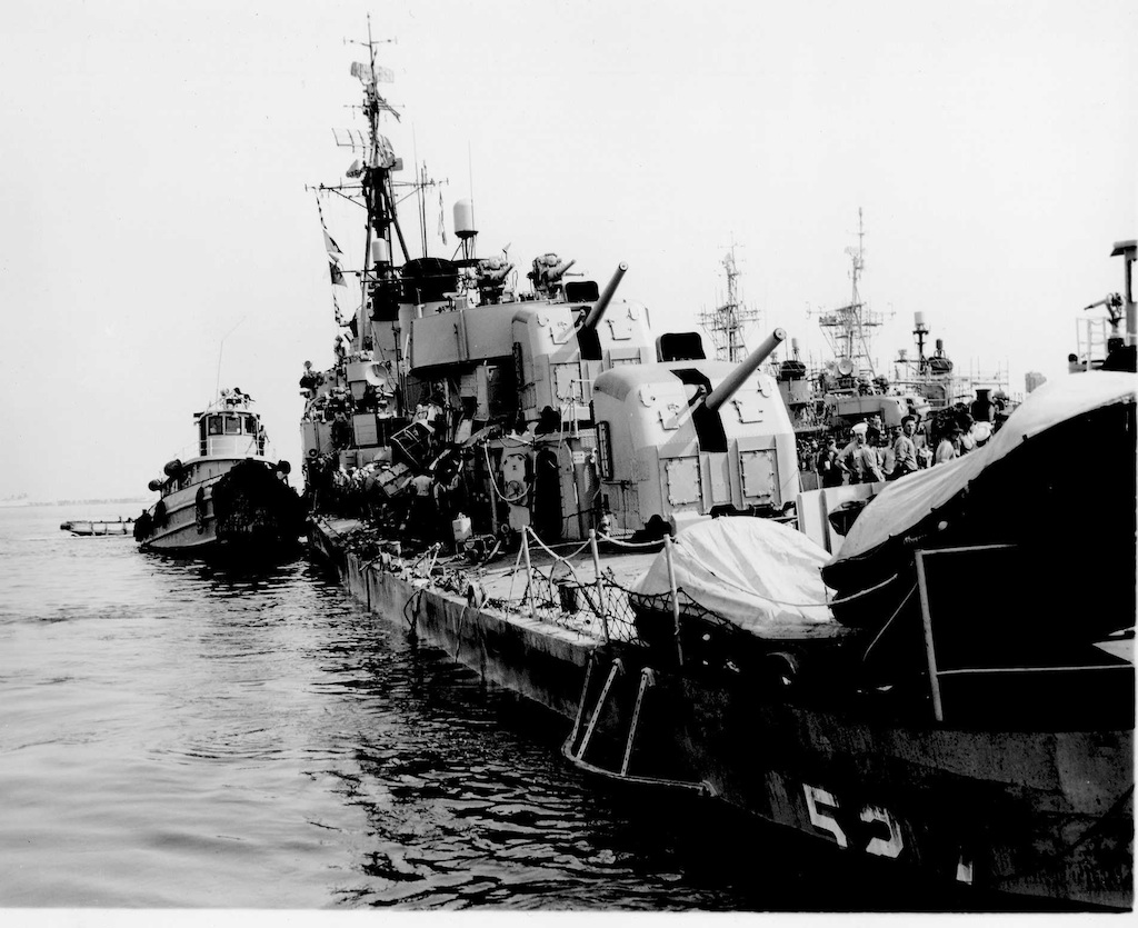
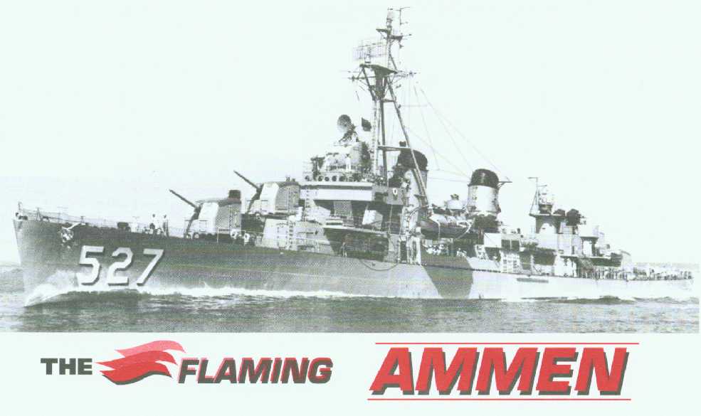
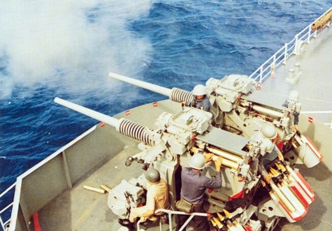
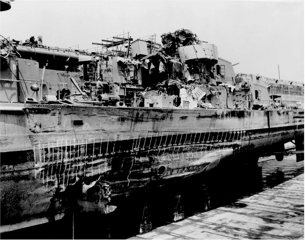
Some photos of the Fletcher I was a gunners mate aboard, we were in a collision on 19 june 1960, killed more than the Kamikaze that hit between the stacks while she was on picket duty in Leyte Gulf, both on the net if interested. The 3" 50 is not aboard the Ammen, but it is a good photo of the 3" gun, the 5" guns are in the configuration you want for the updated Fletcher you have, photo was just after collision, just before dry docking, counter flooding had leveled her out. Doing some nice work, other than the lack of K guns, different torpedo tubes and the hedge hog launcher and guns needing some fine tuning, she looks good, only someone who served aboard such ships would be as fussy as I.

- 31 replies
-
- 10
-
-
Would be happy to except it's long gone, made it in the 70s when my wife wanted some decorated boards for Decoupage or whatever she was doing at the time, routed a bunch for her and friends. All it was, was a 1" X 12" pine board about 2 feet long, drew a circle that matched the router base and routed it out part way through for the base to fit into, bolted the router in and routed a center hole for the bits to fit through. Then attached the thing to a frame of a TV stand I had lying around, sometimes I used a board for a guide, 'fence', used C clamps to hold it in place. Worked well, had both hands free to control the work, took about a hour to make including gathering up the materials. Haven't needed it since and has been a while and several moves ago when I saw it last. Did do something similar using a jig saw that worker better than free hand, it also has disappeared. If the need comes, making replacements will be no problem. All you need is a surface with an opening for the blade or cutter to protrude from, a way to attach the saw or router below on a stand of some kind, C clamps and sawhorses would work, a board and C clamps for a guide if needed. Most of the time a guide is not necessary, many cutters will guide themselves and a jig saw, just follow the lines and finish on a sander. Good luck. jud If your first one comes out a little rough, use it to make a better one.
-
Having built my own router tables using ply board before they were commercially available, I would say no. Would something like it be handy to have around, sure would. If you have the ability to use such a device, you also have the ability to make your own custom version, that is what I would do. jud
-
Those 3 jaw chucks are seldom concentric with the rotating C/L. Two choices, a face plate and turn between centers with a centered head stock or oversize stock so you can true it up, both quick and useful methods. Don't see much about turning between centers on this site but I expect there are some here who use the method. 4 jaw chucks also are good except for the setup time and not often used for turning of round stock. There are instructions on line that will allow you to true up your chucks but they will never reach the precision of collects. Looks like you are getting a good start with you machine knowledge, that with your own observations will be serving you well in years to come. jud
-
Could that be where the issue of two was misinterpreted? Ran some numbers based on the 800 man crew mentioned, each hammock, I will quick guess, without looking it up, as being 6' X 3' for a total of 18 square feet per, without considering lashings rings or hooks, etc.. Each man washing a hammock and using a dry one would be looking for his 18 square feet of the needed14,400 sq feet of drying space on deck to lay his hammock while drying, that is 120 feet square, or 30' X 480' of space, 30' X160 feet on 3 decks, really? Was stepping on someones freshly washed hammock accepted by those owners being stepped on by those looking for their own space or were there some confrontations? Don't know the truth of the tale, but 2 X 2 seems to be coming out 5? Hammock cranes did exist and were used to hold hammocks, no question in that, But something is not quite right in modern mans understanding on how they were used, expect it to be a lonely group of us wondering about this and it really does not matter much anyway. jud
-
Mark, that is the accepted norm, glad to see you introducing some exceptions. 8 bells was the length of the watch as it is today, but it was a Port and Starboard system, anyone who has stood Port and Starboard for long sure grows fond of the 3 watch system. jud
-
OK, I read it. don't think it makes a bit of sense to issue two hammocks to each sailor. Two men to each hammock and hot bunk it would make more sense, except the hammock did double duty as a storage place for each seaman. It is the accepted idea that the hammocks were kept in the hammock cranes except when in use, that's fine. I don't think that was the norm, have pointed that out and everyone is free to make up their own minds. jud So I don't come across as a complete jerk, I did look at your work, was impressed with the quality. Have painted canvas to water proof it and it works well as long as there is very limited movement, doesn't take much for the paint to crack and chip. Where canvas was used on some of the ships I was aboard for awnings or other decorative trim, unlaced and retied into knot patterns, it was kept washed, not painted. jud