HOLIDAY DONATION DRIVE - SUPPORT MSW - DO YOUR PART TO KEEP THIS GREAT FORUM GOING!
×


jud
-
Posts
1,171 -
Joined
-
Last visited
Content Type
Profiles
Forums
Gallery
Events
Everything posted by jud
-
 Is there a university or trade school in your area that is more refined with their equipment and knowledge. Once had to go 150 miles to find a school shop that could drill a pin hole in a hardened hydraulic motor 1" dia. shaft, they kept it a couple of weeks, used it as a class demo., used their equipment to drill with electric spark etching, hole was perfect and it saved me a bunch of money. Think I would produce a well detailed and finished pattern, then cast your cannon, once the pattern is done to your liking, many casting methods are available to you. 3 D printing is still developing and skill in picking the subject, is probably more valuable than the printing method.
- 125 replies
-
- 2
-

-
- 9 pound naval cannon
- 3d cannon barrel
- (and 1 more)
-
I would expect wheels and axles to be well greased using a vegetable oil or grease. That form of maintenance and lubrication would work itself into the wood as a sealer, keeping water out so cracks would not develop caused by water content changes. Color was probably the result of that oily grease, not paint pigment and varied from tan to dark brown during the service life of the Truck Wheel.
-
Does anybody have any experience of this?
jud replied to Moxis's topic in CAD and 3D Modelling/Drafting Plans with Software
Not a surprised that this machine has made an appearance, 3D printing, laser engraving and CNC Routering all require the same software and motion provisions, the only real difference is the configuration of the Head and a way to provide the working Tool requirements to make the cut or deposit material. That being said, I wonder why it took so long for the first to appear. The Spillway gate has began to open, the wise will give it time to develop and sort out the keepers from the Want to Be's. The needed software has been around for a long time, started seeing flat table plotters in the late 60's, adding the Z component was child's play. The Router tool and the printing head are add on's that will see a flurry of development improvement until a best approach reveals itself. That is the time to buy. Let those with deep pockets bear the cost of refinement. -
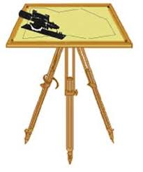
Just found your log active again, glad to see the progress. Your build is beginning to obtain that cluttered look that would have been necessary to sustain Cook and his crew, on that voyage. Surprised and pleased to see the plane table, few even know what they are. I was an instrument Man for a company that had two different Dam projects, they had flown and photographed the route for a relocated road system around the expected lake pool and they plotted all on drawing sheets and wanted us to run the Preliminary Line using the 'Plane Table and Alidade', one of the telescopes had a right angle prism for an eyepiece which minimized the squats but increased the bending over, that work is hard on backs. Anyway I did get about 6 weeks of experience with that technology. Read a book about an American that went on a mapping voyage and although not noted, two plane tables, one on each end of a base line would have allowed them to survey prominent points and prepare a good map with some precision. It was interesting because they used the speed of light and the speed of sound to measure the length of the base lines between boats. They would do the preliminary scouting and choosing the control points for the two boats that were collecting the angles, did not say if they used a sextant or angles from a Compass orientated along the base line. They could easily obtain the Bearings of those Base Lines by several means. The length was needed with precision for determining the positions of their points of interest on the shore. To obtain distance between the anchored boats, they placed small cannons in each boat, the mappers would have stop watches. When all was ready, one boat would fire their cannon, first smoke from the bore was the signal to start the clock, the sound of the shot stopped it. Several shots from each boat would provide an average time to compute distance from, follow up surveys years later revealed accurate work was done using that method. 'Welcome back,', thinking you did some digging to come up with the Plane Table idea, I not only like it, I suspect you are correct.
-
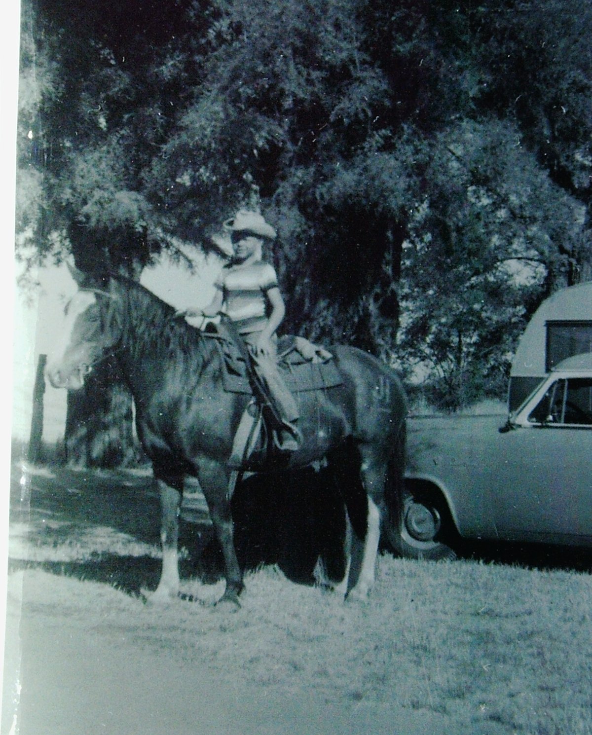
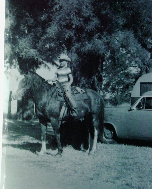
Started early playing with rope. Me, over 60 years ago on my Cayuse Mare. Had to run her in a corner and rope her to catch her. Enough bad habits and tricks so no one but me would ride her, we got along fine. Bucked Dad off 3 times in a row before she had him properly educated that she was my horse, not his.
-
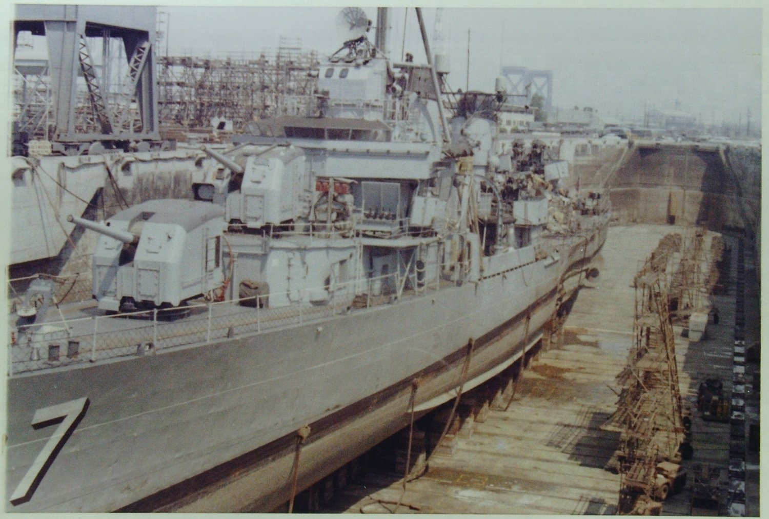
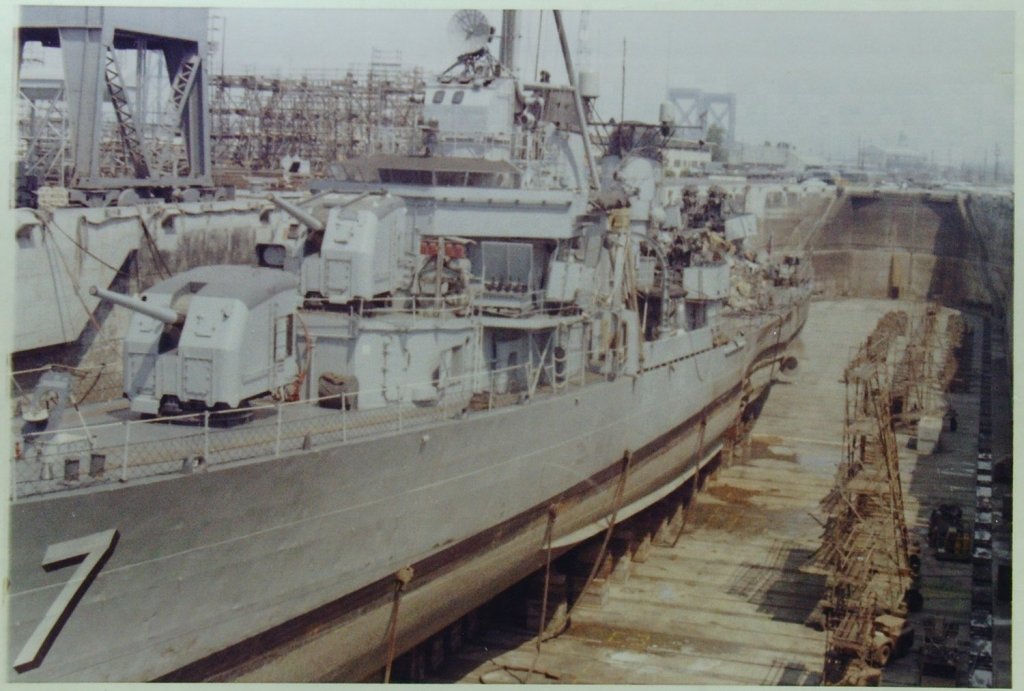
The first 58 Fletcher's ordered were referred to as the High Bridge or Round Bridge. The remaining 117 Built were referred to as Low Bridge or square Bridges. The change was made to provide more anti aircraft defense, had nothing to do with the coast they were built at. The Sullivians DD 537, was a Low Bridge as was the USS Ammen DD 527, which I served aboard as a Crew Member before the Fram Modifications became common. Photo is the USS Ammen by me in a Long Beach Drydock after the 19 July 1960 collision with the Collet DD 730 off of Seal Beach, California.
- 140 replies
-
- 10
-
-
- the sullivans
- trumpeter
- (and 2 more)
-
You need to go find a Seaman or a Working Cowboy, and ask them how they would tie such a line to a rail without open end access. Just doubling the line back on itself, making a couple of turns around the rail secured with a half hitch would produce a secure and handy hold-fast, throw another half hitch and you could hold the world. Reread carefully what wefalck said, believe there were some conditions about using the clove hitch you may have missed, his best advice was hidden from most who lack experience.
-
Going to be sitting in on your Sullivans build, My first ship was the USS Ammen DD 527, a Fletcher, so your model will look like home to me.
- 140 replies
-
- 6
-
-
- the sullivans
- trumpeter
- (and 2 more)
-
Don't know what your line of interest is used for, but it is unlikely that you want it to be tied with a knot or hitch that draws up tight and is slow and difficult to untie. Also sounds like there is plenty of line left over to make up into a coil, so any knot or hitch requiring the bitter end to be threaded through it's self would be a poor choice. There are several quick release knots available to use, I would probably just use the single overhand knot and tuck a doubled piece under the loop so I could grab the free end and jerk the knot apart, the coil could lay on the deck or you could lash it up with small stuff, every sailor has a knife handy to cut such lashings. Toggles are sometimes used as safety's on those knots or tuck a piece of line through the loop where a toggle would go.
-
H.M.S. Atalanta - Drafting my own plans
jud replied to Ben752's topic in CAD and 3D Modelling/Drafting Plans with Software
At scale, using a median that expands and contracts with humidity and age, who has the tools to measure such small differences? Be difficult at full scale using the materials at hand and the measuring tools of the day. With computers it is handy to have precise mathematical data so that not accounting for minor details does not slowly accumulate and distort the whole. When Surveying, I did my Comps. to ten thousands, drawings were shown to hundredths and to be truthful on the ground be lucky to hold tenths, when monuments were set, time and natural movement moves things around, so discovering later measurements does not match the record is normal and seldom caused by mistake or sloppy work. If you have the time, tools and ability to take such things into account as the tapering of framing, great, just don't then forget that the outside of each frame is on a curve and not account for that also, most have little need for such detail to build dimensionally acceptable models at scale. The refinement of the data can get very detailed or it can be limited to actual useful data to accomplish the task at hand. -
Made one that used the whole firecracker for the propelling charge, Small threaded pipe, a couplier with a bored out grease zirk to run the fuse through. Hand held pistol like grip, worked fine except lighting that fuse and waiting for it, was impractical, after firing, most of the firecracker remained in the chamber and needed to be removed, accessed by unscrewing the zirk, scrape out and reload. Don't know where it ended up. Those things were always made so the projectial had little resistance, didn't take much to get it out the bore, even those that fired 22 ammo, I started the bullet from the case before loading. Never damaged or hurt anyone doing this stuff. I knew what I was playing with, had heard all the stories about kids being injured or killed, Loaded firearms were available to me all my life, so was aware of the energy involved. Loaded rifles were next to the doors to grab and go with, considered tools and were no mystery or conditioned fear of them, just part of the household.
-
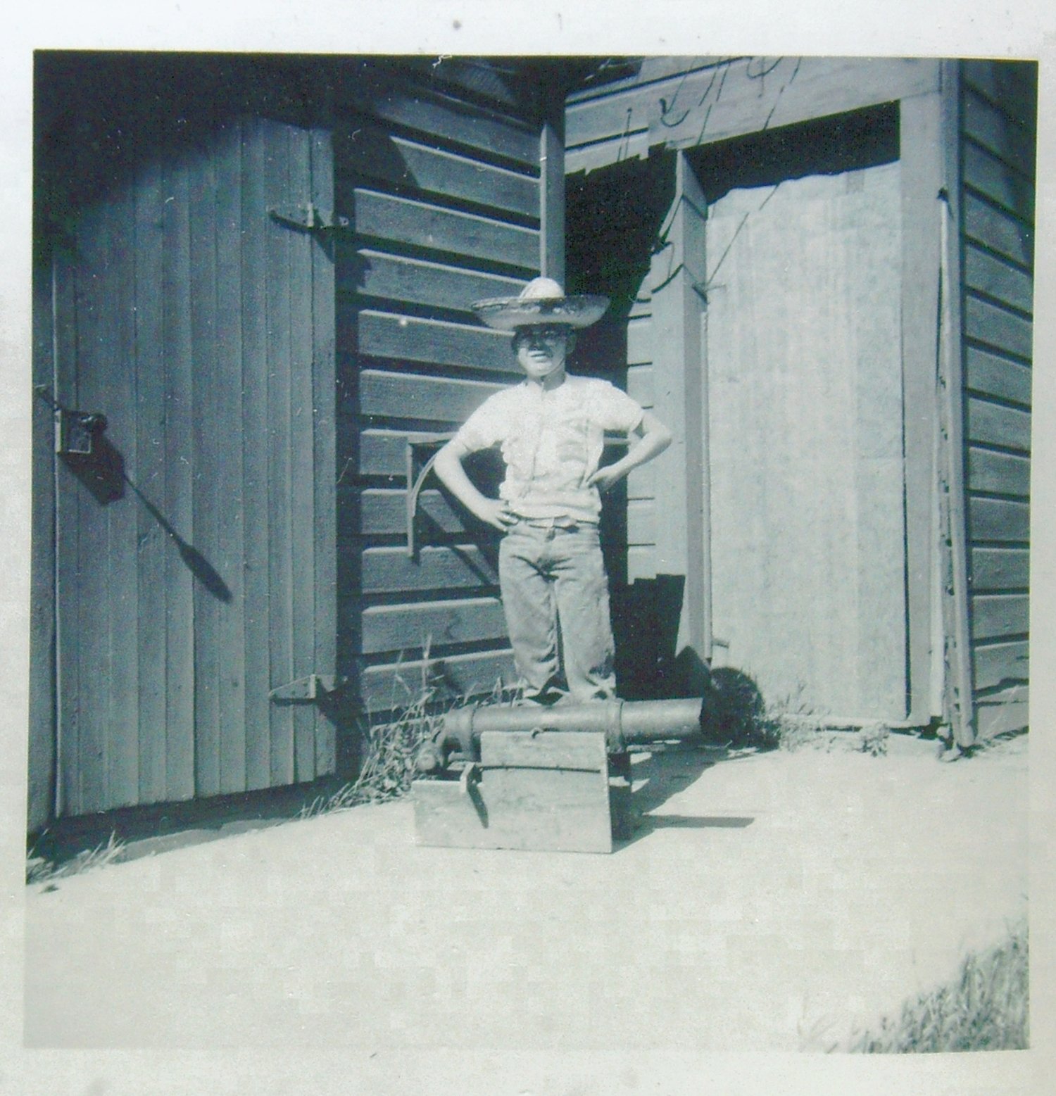
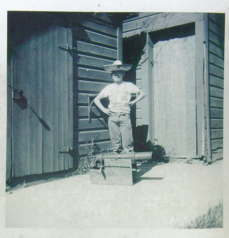
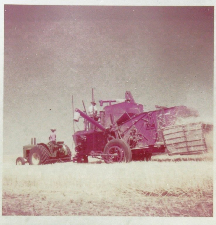
Should not be much of a problem with ring bolts. As a kid, I made at least 6 out of various stock and used black powder in them without excessive recoil except for 2 instances, one was a little over a 30 cal and loaded it with ample powder packed well, used wading around a 30 cal bullet and rammed it, it was a boat tail or I couldn't have started it, I stapled it to a 2 X 4 and buried the 2 X 4 into a hole in the dirt and packed the ground around it, the gun was up about a 1/4 inch, block stayed where I put it but was loose after the stapling failed and the barrel moved about half it's length rearward. The other was a 8" brass napoleon that I bought, shot ball bearings and BB's in it. Wondered what it would do if I filled the bore clear up with black powder, so I did, leaving room for wading. that time it flipped over on it's back, no harm done to the gun. Normal loading of any of my guns never produced any destructive recoil, Force, Mass and Distance tamed it well. This one only shot full rolls of caps and made ample noise and some smoke. Was 13 when I put i together. Pulled the combine in wheat harvest the same year, that is Dad on the machine, plenty of work for a kid on a ranch in the 50s.
-
Chock, the kind you can buy for a Blackboard are good fillers for files. With a clean file just rub the chock over the teeth, knock the loose chock off and it will help prevent plugging. I use in on files and rasps, transferring chock to your work should not be a problem, wiping a rag over the teeth before use should prevent that. Use diamond hones for edges, never had a diamond file in my hand.
-
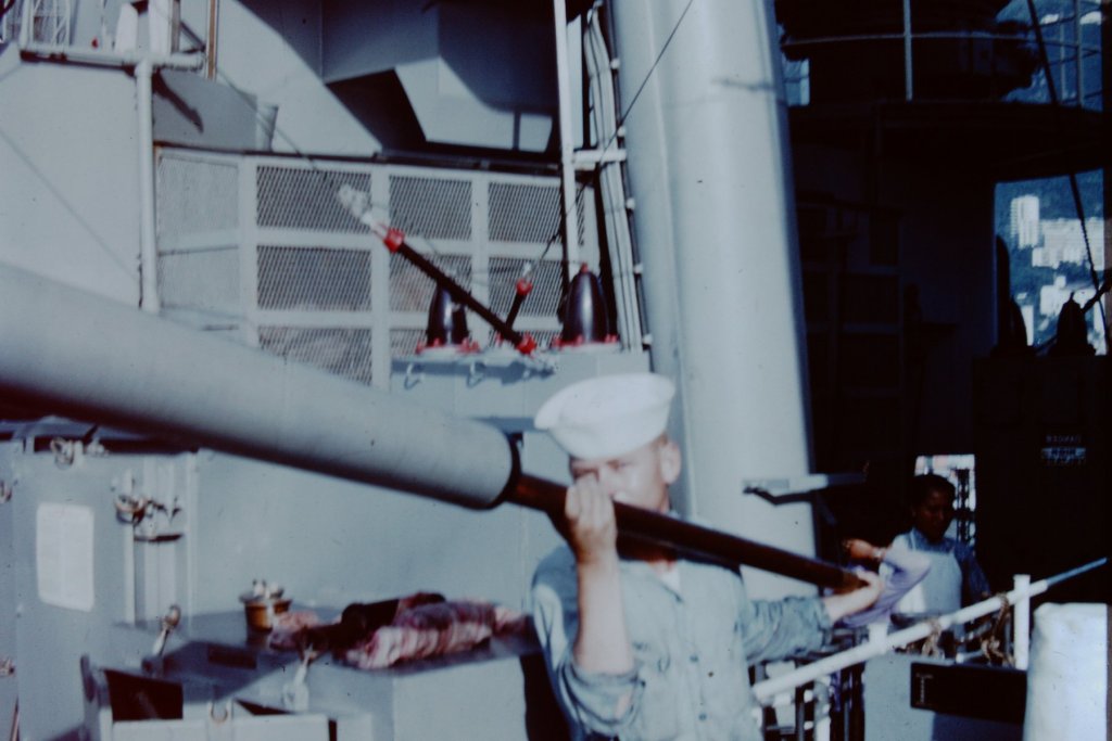
Cannon Maintenance. 3"50, Mount 34, USS Helena CA 75, 1961.

-
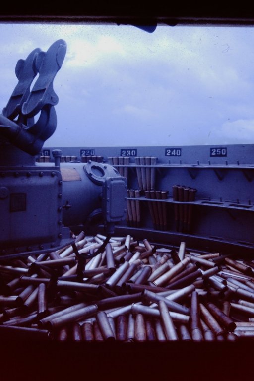
When fast torpedo boats and aircraft came into their own, going to Action Stations or General Quarters in a war Zone for Sunrise and Sunset became the norm, because attacking from out of the sun just coming over the horizon or dipping into it was advantageous, with the Radars and Gun Control Systems of today, not so much. Although ready service ammunition was at the gun or very close to it, it was not normal to load it, in the days of sail there was plenty of time for that and as Breach Loaders became the norm, it did not take long to load the guns. Muzzle loaders had, as part of their equipment a large screw device with a pointed end to the screw all mounted to a ramrod. It was used to work the projectial loose so it could be withdrawn or rolled out on it own and the powder bag also was hooked and withdrawn with that tool. Fixed ammo for a breach loader all is contained and held together by the cartridge case that is manufactured with a way to control head space and to extract the cartridge with or without it being fired. With rifled guns the lands and groves do not start abruptly, there is a forcing cone built into the barrel that allows for transition for the rotating band or brass bullet jacket to fit itself. On Semi Fixed or Bag type guns, all that is there but the rammer does not ram the projectial far enough into the forcing cone that it can't be backed out with a ramrod through the muzzle if it does not follow the cartridge out with a raised muzzle for Semi Fixed Ammo, Bag Guns require the ramrod after the powder bags have been withdrawn. and are a pain in the butt unloading in any manner but through the muzzle, in other words, shooting the dam thing. Never had to unload a Bag gun, we did not load them unless we intended to shoot and the loading was done on command, not an automatic part of manning the guns. Have unloaded many times misfires from 3"50s and a few 40MM Bofers, but always attempted to get them to fire by rigging a firing circuit or in the case of the 40 MM Bofers re-cocking the firing pin. Re-cocking the firing pin on a Bofers is not taught, because it involves unlocking the breach, but by marking the side of the housing at the point the cocking lever can be moved to, too re-cock without moving the breach can safely be done. The first thing I did when going aboard a ship with Bofers was to determine that spot, and mark it with red paint. Photo of some ready service ammo and a few empty's, Mt 46, Harnett County LST 821, TF 116, TU 76.8.3, RVN 1967.
-
Congratulations on a job well done. Need to copy this log onto a couple of Thumb Drives, one to go with the model and one to keep. jud
- 749 replies
-
- 3
-
-
- albertic
- ocean liner
- (and 2 more)
-
If and when that glue breaks down, those coils should be well trained and stay as they are.
-
Was a discussion on this subject several years ago, venting the case using cotton waist as a dust filter was one of the solutions.
-
Built that model in 72. Only rigged the standing rigging and my painting was with a brush. Would have been a big help and had a nicer outcome if this site had existed, my experience with modeling was with the Ships, automobiles and airplanes available in the late 50's up to about 66, so the results were rough, but she looked good up on the shelf, dust was a problem and after some top-hamper was damaged, I gave it away. Will be watching, makes an attractive model and worth the effort to build.
- 82 replies
-
- 3
-
-
- revell
- cutty sark
- (and 3 more)
-
All encompassing compass considerations
jud replied to JerseyCity Frankie's topic in Modeling tools and Workshop Equipment
Bruce, have one similar hanging in it's box on the peg board, $16.95 in 1994 on the tag glued to the box., 'C2E Bavarian' 6 1/2". -
All encompassing compass considerations
jud replied to JerseyCity Frankie's topic in Modeling tools and Workshop Equipment
You are not drafting for others, quality requirements are yours to determine. You have been presented with options with reasons. Being the judge, obtain what you wish, if it someday needs upgrading, you now have some background about what to look for. -
All encompassing compass considerations
jud replied to JerseyCity Frankie's topic in Modeling tools and Workshop Equipment
Have several drafting compasses that are for lead and ink, they are equipped with two outside heads, the lead sticks and a piece of sand paper are easy to obtain. The Ones I prefer are the drop bow type, they have an inner radius needle that slides so you can place the point on the mark unencumbered with the rest of the device and when satisfied the point is where it needs to be, release the remainder of the tool and draw the circle.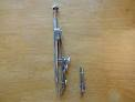
-
There are also Tides in this world where that happens, like in Alaska. Tying up to a piling supporting a dock, do it so the line will slip up and down with the tide, then stand watch over it, or go anchor with plenty of scope on the anchor line.,
-
The stop bars on the drain doors would restrict the opening arc. I suspect it was discovered that without them, with the laden ship in heavy sea's, there was a tendency for those doors without stoppers to be opened a bit by gravity then caught and lifted wide open by outboard sea's, allowing more water to come aboard. Stoppers would greatly restrict that flooding and outboard water acting on the outboard face of the door might close and hold closed, that door. Kind of like a flapper valve in a bellows. Regardless, this is a fascinating and well executed modeling of a ship whose time has long ago passed. jud
- 281 replies
-
- 3
-
-
- falls of clyde
- tanker
- (and 2 more)