


EdT
-
Posts
2,214 -
Joined
-
Last visited
Content Type
Profiles
Forums
Gallery
Events
Everything posted by EdT
-
Rob, your measurement of .155 for 10 turns, if it is a No. 30 thread sounds about right to me. My measurement of DMC 40 by this method is .135" and .17" for DMC 20. All to be divided by 10 of course. At 1:72, I use DMC40 for 3" line and DMC20 for 3 3/4". Some suggestions: the turns should touch but not overlap, the tension should be about what you expect on the model - snug but not overly tight. I use a 1/2" dowel. The best way to increase accuracy is to increase turns - 10 happens to be convenient and I believe sufficient. You are correct in not compressing the turns with the calipers. I have a lot of thread, so if you tell me the thread you are using, I would be happy to measure it for comparison with your measurement. We should be careful here not to get hung up on precision. Proportionality to the model and consistency between rope model rope sizes is more important than absolute precision. All these measurements will be approximate, as will assignment of a particular thread size to a model rope size. A 3" rope should look about half the diameter of a 6" rope. At 1/128 scale. the smallest lines, say 1 1/2" ratlines, will be only .004" diameter. The smallest thread I use is 100 crochet cotton that I measure at .008" - this would be about right for a 3" line at 128 scale. I have some Coats T1 and T4 mercerized polyester that I have measured at .004" and could be used for your ratlines, but it would have to be de-fuzzed. Assignment of thread or made rope to model rope sizes takes some time, some judgement, and some compromise so that the lines look right in relation to each other and in the right proportion to the model itself. Ed
- 3,618 replies
-
- 5
-

-
- young america
- clipper
- (and 1 more)
-
Circumference. Rope size was always expressed in inches circumference - in rigging tables, drawings, documents, etc. so that is the common usage. It would also be easier to measure with a length of string or tape in the absence of calipers. Measuring circumference is impractical at model sizes, so diameter is used to measure of threads and ropes - with conversions to circumference to relate to sizes in tables and other rigging documents and to apply common rules of thumb for relationships between, say for example, rope size and block size. I should clarify my comment about only rope 4" and above being "made". I should have said that all rope 4" and above is made - that is, spun into rope from threads. I actually do use made rope in some smaller sizes that fit between common the common thread sizes. Ed
- 3,618 replies
-
- 5
-
-
- young america
- clipper
- (and 1 more)
-
For example, Rob: 10 turns of DMC40 cotton thread measures .135", divided by 10 the thread diameter is .0135" which at 1:72 converts to 72 x .0135" =.972", times 3.14 (pi) this equares to a circumference, ie rope size, of 3.05", so I use this thread for 3" rope - about the average size. Keep in mind that measurement error makes all these sizes approximate, but certainly adequate for modeling. Ed
- 3,618 replies
-
- 3
-
-
- young america
- clipper
- (and 1 more)
-
Thanks everyone. Paul, I appreciate the difficulty of visualizing many of the lines and will try to put arrows where it will be helpful. Living with this everyday, it is easy to underestimate the difficulties. Johann, I looked at your post with the thread. I am not familiar with that brand of linen and would like to know the name. It looks good, fairly tightly wound. Some fuzz, but this may be removed after the rope is made by passing the line slowly through an alcohol flame, a process called "gassing" in the thread industry. The best test is to make some rope, dye it, gas it, then make a judgement. With linen, slubs are the big problem. None are visible in your photo. I use quite a bit of DMCcotton thread and like it. It is somewhat softer than the other brand I use, Fincrochet. I use these interchangeably in sizes 100, 80, 60, 40 right off the spool and to make larger ropes. All get dyed and passed through the flame - twice. The numerous 3" lines on my model are DMC 40. The 1 1/2" ratlines are Fincrochet 80 - for example. Rob, thread sizing is nightmarishly complex with numerous systems. You may wish to research thread measurement online. There are several good explanations. Generally the larger the number the smaller the thread. Sometimes the number of plies is shown, for example 100/3 or 60/2. Measurement is the best bet. Wrap 10 turns evenly around a dowel, measure the overall width with calipers and divide by 10 to get the diameter. This is more accurate than trying to measure a single thread. I used a lot of small mercerized cotton-polyester on my Victory model and after 10 years it looks the same. I believe polyester is for strength and cotton for the finish. Polyester may be less susceptible to the effects of moisture than natural fibers. Ed
- 3,618 replies
-
- 2
-
-
- young america
- clipper
- (and 1 more)
-
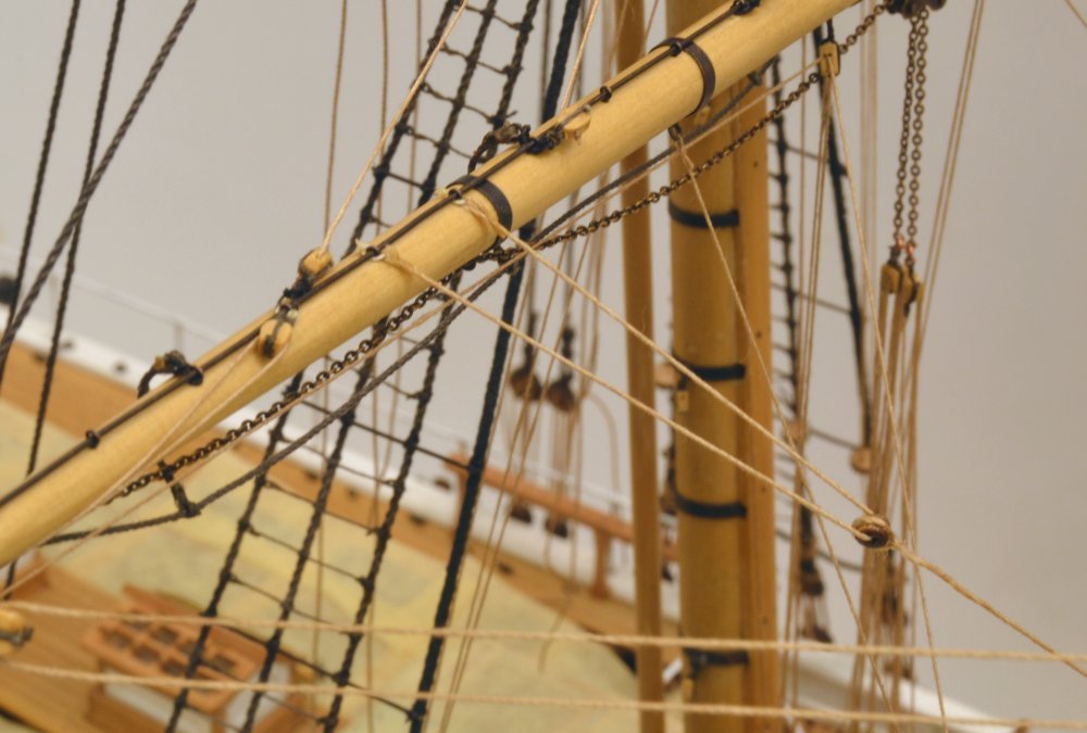
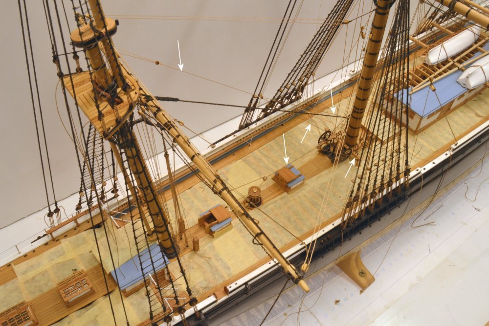
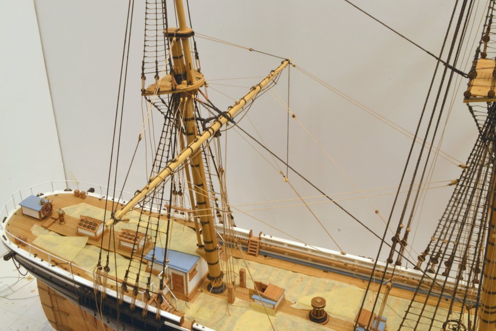
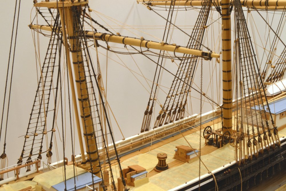
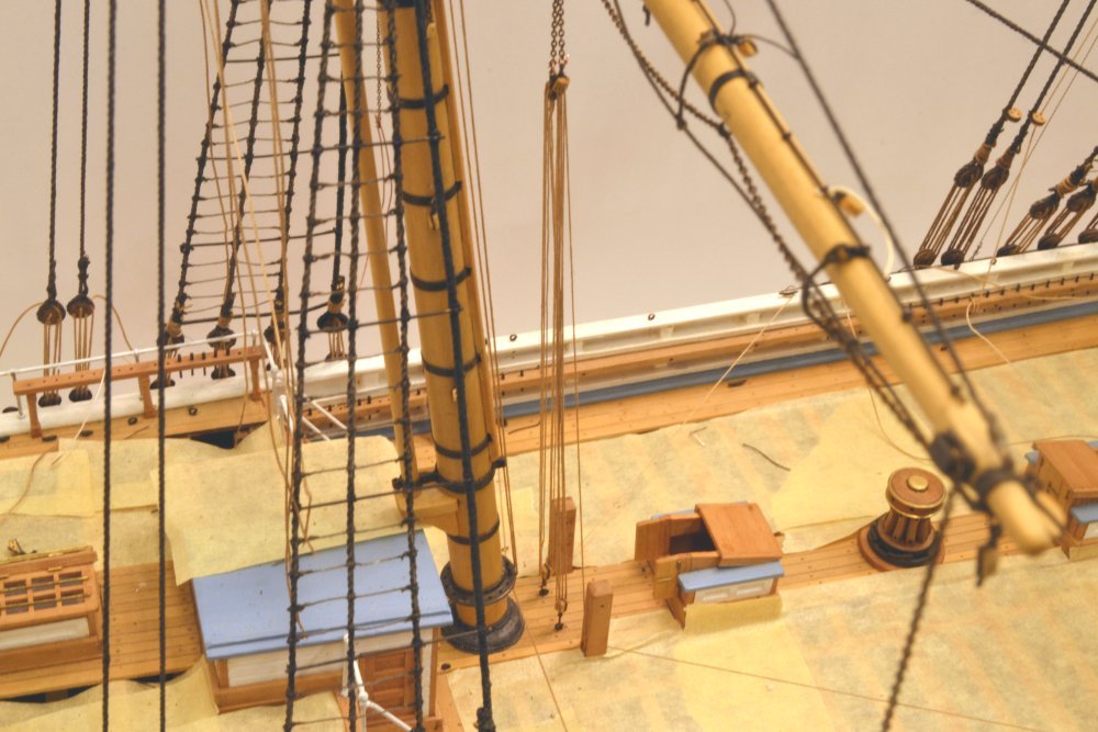
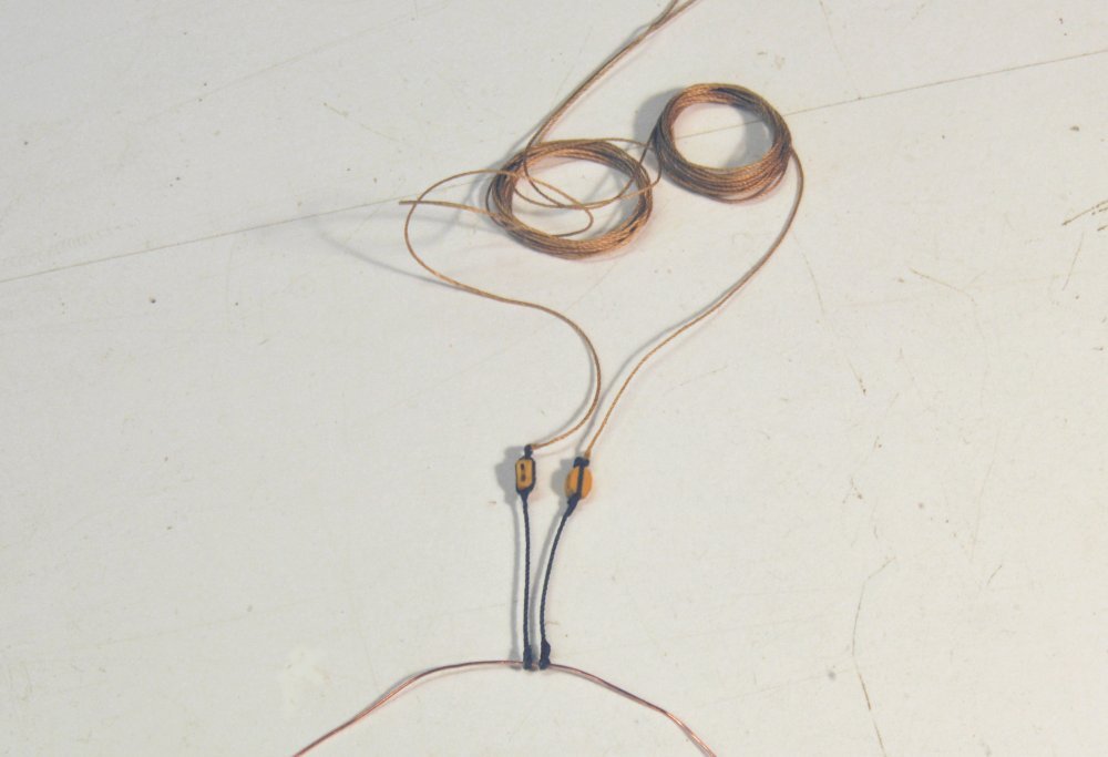
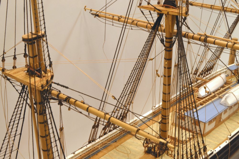
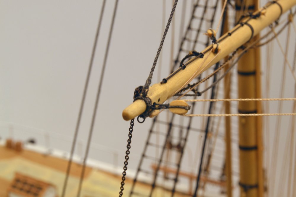
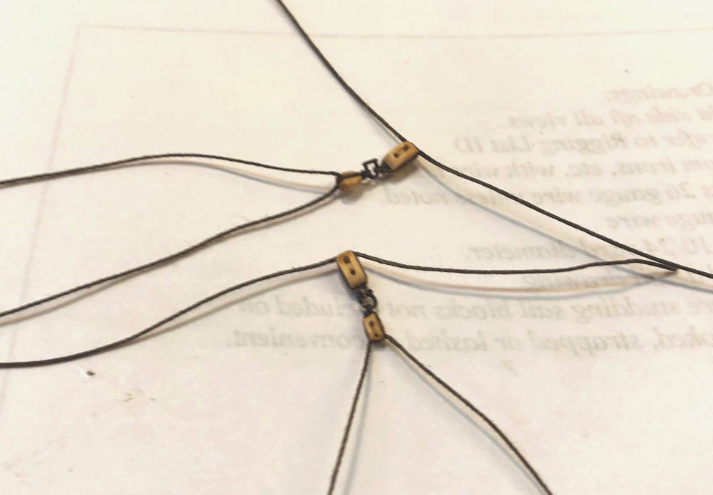
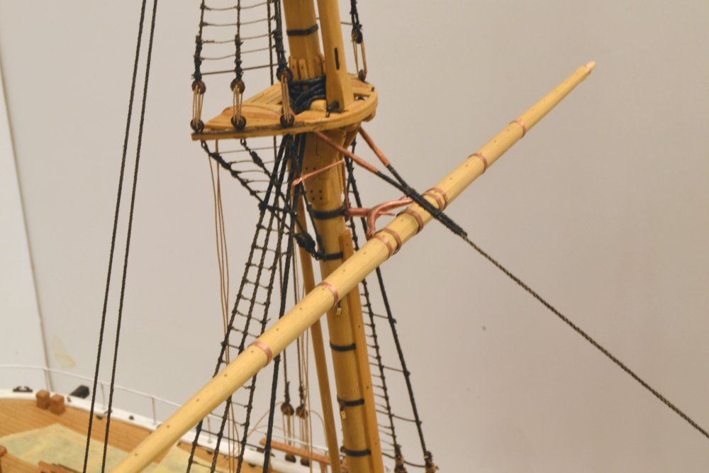
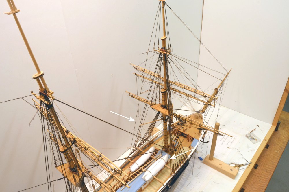
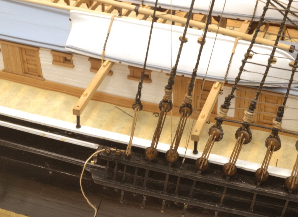
Young America - extreme clipper 1853 Part 299 – Crojack Yard 4 This part will wrap up the rigging work on the lower mizzen yard – aka the Crojack. The last lines to be installed were the bowlines. These were used to control the windward leech of the sail when the yards were braced at an angle. They consisted of three parts each: the 3" bowline, itself, a 3" lizard" about 25' long, with bullseyes spliced into each end, and one or more "bridles". The single starboard bridle is shown in the first picture. This is about 20' long and also 3". The splices at the ends of this would be fastened to the bowline cringles on the sail, but since there are no sails on this model, the bridle is tied off to the jackstay where it could be cut loose and tied to the cringles when "bending" the sail to the yard. The picture shows the upper bullseye of the starboard lizard. The the full length of the lizard is shown in the next picture. The next picture shows both bowlines installed, with arrows to help see the parts of the lines. The standing end of each bowline is secured to the lower part of the mizzen topmast stay, passes up through the lower lizard bullseye, and finally belays on the outer arm of the main mast fife rail. The last two pictures show the fully-rigged crojack at this stage. The loose chains hanging from the ends of the yard are the lower topsail sheets that will be connected to the clew lines when that yard is rigged. So, as I mentioned in one of the responses, this is the seventh spar to be rigged, with another dozen to go – most being simpler, however. Ed
- 3,618 replies
-
- 24
-
-
- young america
- clipper
- (and 1 more)
-
Understood, Druxey. The spinning just takes a bit longer. Ed
- 3,618 replies
-
- 1
-
-
- young america
- clipper
- (and 1 more)
-
At the risk of getting too worked up over the linen-cotton comparison, I took the two photos shown below. The first photo shows three white threads labelled by type In this picture the Lacis lace-making linen is decidedly more fuzzy. Not so clear in this picture but probably in the next is that the linen on the right is less tightly wound and has more variation in diameter. In the next picture, taken closer-up, the same threads have been dyed with the aqueous natural walnut stain that I use for hemp rope. This highlights the twist and seems to suppress fuzz. Fuzz is not a too major an issue since all ropes are passed through a flame to remove it before use. The twist direction is very visible in this photo. The right-handed cotton is very uniformly wound and simulates rope very well. I use this size for 2 to 2 1/4" inc rope. The Barbour linen is more tightly wound than the Lacis and the left-handed twist is evident on both - though less pronounced than the uniform twist on the cotton. For these reasons linen thread alone is not a good choice for right-handed rope. However, its left-handed twist makes it easier to spin up into right-handed rope. When I get the Londonderry thread I will get some comparisons with that , including some made rope. Ed
- 3,618 replies
-
- 9
-
-
- young america
- clipper
- (and 1 more)
-
Johann, thanks. As a linen enthusiast, I would not want to discourage you from testing it. Also, I have found that slubs in the linen thread may sometimes be picked out of the strands with tweezers before spinning to reduce their visibility in the finished rope. STM, thanks, I do agree that it is easy to spend too much time on this issue - I know I have. Also, I would not use linen thread straight from the spool, if only for the reason that all I have seen is left-handed, and small left-handed lines would be rare. All the lines on YA are right-handed. If you could associate a brand with the AMMG standard that would be helpful. I have ordered some Londonderry 100/3 linen and will try it and report back. Ed
- 3,618 replies
-
- 4
-
-
- young america
- clipper
- (and 1 more)
-
Thanks for the tip, Dowmer. I will get a spool and try it. Ed
-
Johann, Your posts are quite understandable. Do not be deterred by this. Your rope-making gear looks a lot more sophisticated than mine and should serve you very well. I assume the the sliding tray for the top moves very freely along the track. It appears that the "looper" is not motorized. This means that the hook must rotated very freely allowing the rope to be wound up entirety but the torque from the twist in the strands. It looks like you are well equipped. Friction is the major issue with this configuration - and equal tension on the strands. Finding good quality linen thread is another matter - and a real problem. The thread I use was made by Barbour Co. of Lisburn, Northern Ireland. I believe it was used mainly for veterinary sutures. It is almost entirely free of slubs - bumps in the thread from irregularities in the flax from which it is spun. Barbour was sold some years ago and taken over by Coats - a large sewing thread manufacturer. I have found that their quality is not nearly as good and that the finest size, No. 100, does not appear to be available. This is the most useful size for making model rope. My guess is that bookbinders, that primarily use the product today, are probably not too concerned by slubs. The other primary use, I think, is lace-making. I have tried lace-making linen without much success, but this may be a better source in EU - perhaps Belgium. I suggest an online search for "linen thread" but I would not be optimistic - based on my experience. Hopefully, you will have more success. After being committed to linen, I have found crochetting cotton to be a very satisfactory material and use both DMC and Fincrochet brands for making rope and as-is for smaller lines. This thread is made from long-staple, probably Egyptian, cotton and has no synthetic content. I have experienced no noticeable stretching with changes in humidity, but will be more comfortable after this winter. We go from very low humidity in the winter to sometime over 95% in the summer. Hope this is helpful to you. Good luck. Ed
- 3,618 replies
-
- 4
-
-
- young america
- clipper
- (and 1 more)
-
Thank you, Johann. I admire your work very much so your comments are really appreciated. How do I make rope? Ropemaking is such a big topic that I did not try to address it in these posts. I do expect to provide detailed information on the methods I use in Volume III of the books. There are many ways to make rope and many methods have been described - some no doubt better than the way I do it. Only lines 4" and above on my model use made rope. Smaller lines are crochetting cotton (DMC or Fincrochet) right off the spool - white, that I dye with diluted India Ink for black and natural walnut stain for hemp. This thread is right-handed so it models rope well. In making rope I use linen for most standing rigging because it is harder less prone to stretch, but linen thread quality has deteriorated and finding good quality linen and small sizes is difficult. Linen is also laid up left-handed, so it makes right-handed rope quickly. I use cotton crochet thread to make larger running lines. Because cotton is laid up right-handed the strands must first be unwound then rewound to lay up right handed line. This just adds some time to the process but results are still good. I use a ropewalk much like the one described many years ago by Longridge, with many modifications over the years - mostly to overcome various effects of friction and unequal tension in the strans. I use a hand drill for spinning the strands via a four whorl gearhead, normally using only three whorls. Unlike Longridge, I use a motorized louper to wind up the rope after spinning the strands. Setting the amount of twist in the strands and tension in the strands are key variables. Sizing line based on different combinations of thread size and threads/strand is time consuming up front work in addition to setting the variables for each size and material. I am not sure how much more I can tell you without a major dissertation. Considering the amount of made rope on this 1:72 model, the initial set up and testing is considerable. Other processes and hardware may be more efficient. Ed
- 3,618 replies
-
- 8
-
-
- young america
- clipper
- (and 1 more)
-
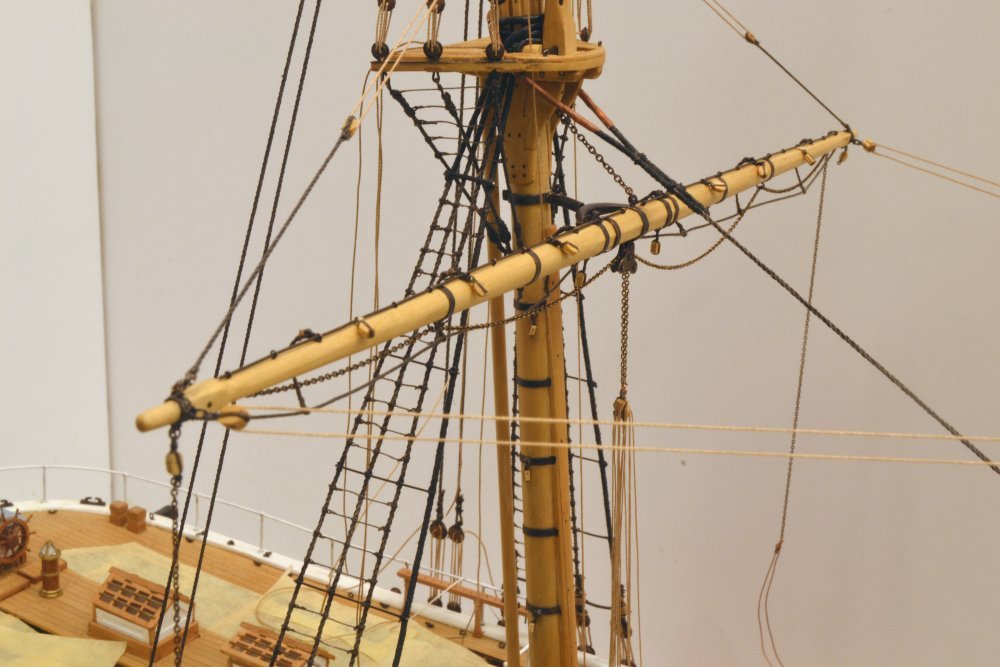
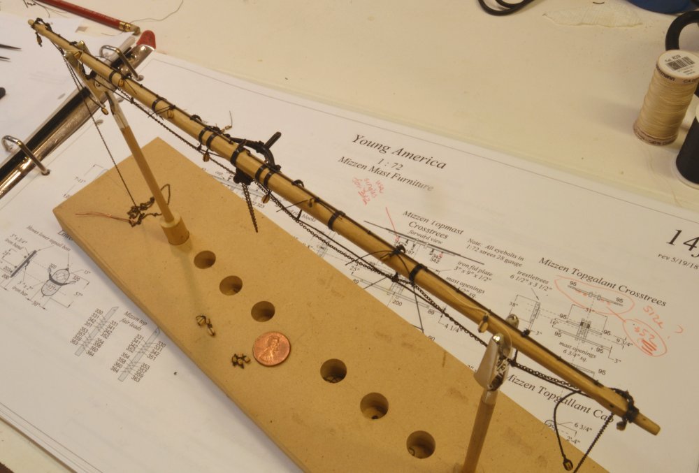
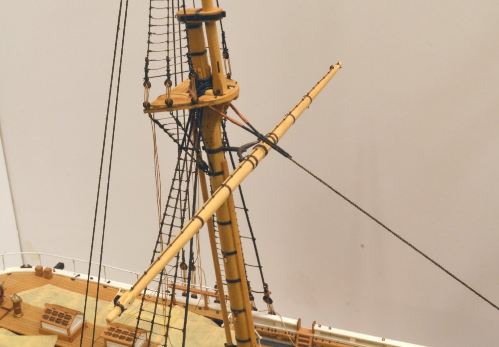
Young America - extreme clipper 1853 Part 298 – Crojack Yard 3 In the first picture, the yard has been permanently hung on its truss, the sling chain fastened to the mast, and the two triple tackles for the lower topsail yard sheets rigged. These are shown in the first picture. The tackles are fixed to the sheet chains with wire shackles, formed in place. At the lower ends the blocks are hooked to deck eyebolts. The tackle falls pass through sheaves in the sheet bitts and will be belayed on pins through those bitts. The next picture shows the two yard braces with their pendants. I am installing the mizzen braces as each yard is rigged because they run forward toward the center and should not interfere with later rigging access like those on the forward masts that run outboard. Those are being deferred until later. In the picture the two pendants are threaded on to a wire that will form the common shackle by which they are secured to an eyebolt on the main mast. The next picture shows that shackle being formed. To make the shackle, the wire is passed through the eyebolt from both sides. A single overhand loop in the wire is then pulled tight through the eyebolt to simulate a shackle. The wire will later be painted black. The braces are spliced to eyes in the block straps as shown in the previous photo. The lines then run through blocks shackled to eyes at the yard arm, back through the pendant blocks and are belayed on the main mast fife rail below. The next picture shows the run of the two braces. The next picture shows the brace connection at the yardarm. The blocks are shackled to the forward band eyebolts on each side as shown below. The next lines on this yard to be rigged were the clue garnets with their sheet blocks, tacks and lazy tacks attached, followed by the bunt and leech lines. These are virtually identical in configuration to their counterparts on other masts that were described in earlier posts. They may be seen in the next photo. The clue garnet blocks are positioned by temporary belaying of the tacks and lazy tacks. This will be adjusted later when the sheets are rigged. These, along with most other outer rigging is being deferred until later to maximize access. The next picture shows the bunt and leech line blocks on the yards and hooked under the top. These six lines pass through fairleads on the lower shrouds, then belay on the main pin rails port and starboard. The reef tackles were then rigged, one of which is shown in the next picture. The standing end of the reef tackle is spliced to an eye on the yardarm block that is shackled to the bottom eye on the yard arm band. It then passes through a block tied off to the jackstay as shown, then back through the outer block, inward to the double quarter block on this side, then down to the fife rail. This picture also shows a close view of the shackled brace block and the shackled topping lift pendant on the top eye of the band. The loosely hanging chain is the lower topsail sheet that will be rigged later. Whew! These descriptions are like a rewrite of the rigging list. Next, the bowlines. Ed
- 3,618 replies
-
- 34
-
-
- young america
- clipper
- (and 1 more)
-
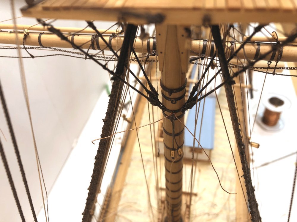
Thanks again for all the comments and likes. Rob, there are two sheaves through each topmast, one at the base and one toward the top just under the hounds. The upper sheave carries the halyard tye for the mast's yard. The halyard tye, usually chain on these ships, supports the yard by the center band, then passes up through the sheave and down behind the mast where it is connected to a gin block, at least on the larger yards, that is used to haul up the yard. The lower sheave has no operational purpose and thus no rigging. It is used to erect and lower the topmast. To do this,with the topmast set vertically and just forward of the mast below, a tackle is rigged from the mast cap above, passing down through the forward opening in the top (or crosstrees), through the mast sheave and back up through the opening to the tackle block. This sheave is set at an angle through the mast to allow the tackle ropes to clear the tight framing of the opening. Striking down topgallant masts was quite common at sea. Topmasts less so. Lower yards would have to be removed or swayed out of the way to strike or raise a topmast. One item to note: Topmasts were normally of a length to fit between the deck and the underside of the top. If longer, a hatch would be required in the deck just forward of the lower mast to accommodate the excess length. Kurt, thank you for your interest in the books and shame on you for losing the beautiful dust jacket with the painting of YA in the Irish Sea off Liverpool by Derek Gardner - one of my favorite marine artists. It is true that I am an engineer by training and by profession, at least in my early years. Although I try to avoid the stereotypical engineer labeling, it is sometimes hard to suppress, with ship modeling being prime territory for its emergence. At the risk of being too meticulous, I want to point out an omission in the last post. The photo showing all the yard blocks is incomplete in that the leech line blocks are not in place. I had installed, then removed them in some confusion over whether these were used on the this yard. They were - and they have been re-lashed as will be seen in the next posts. And Maury, my wife would never call me patient - or when it comes to things I do for her, meticulous. Ed
- 3,618 replies
-
- 6
-
-
- young america
- clipper
- (and 1 more)
-
Pandora by marsalv - FINISHED - 1:52
EdT replied to marsalv's topic in - Build logs for subjects built 1751 - 1800
Congratulations on the medal and on the beautiful model. Ed -
HMCSS Victoria 1855 by BANYAN - 1:72
EdT replied to BANYAN's topic in - Build logs for subjects built 1851 - 1900
Nice work, Pat. There must be a ton of these hammocks to make? Ed- 1,013 replies
-
- 3
-
-
- gun dispatch vessel
- victoria
- (and 2 more)
-
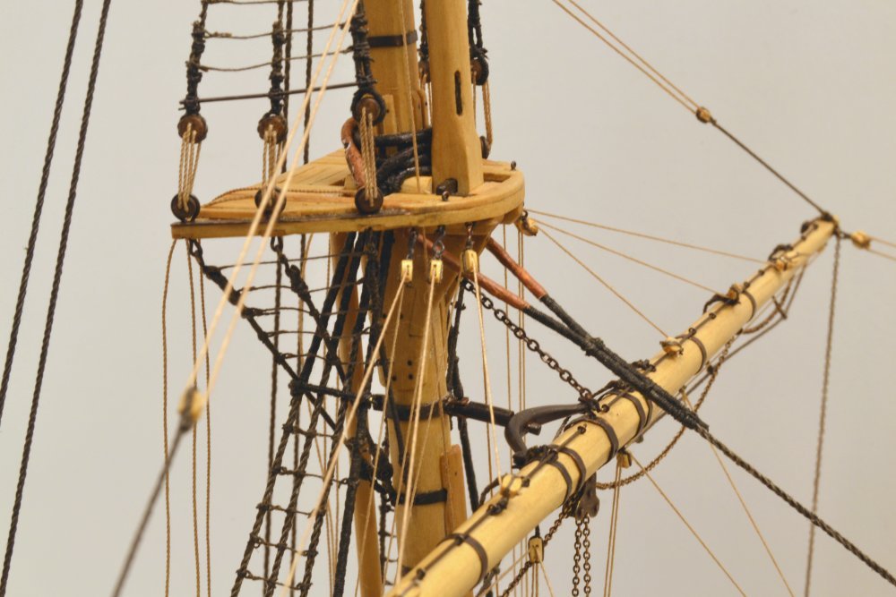
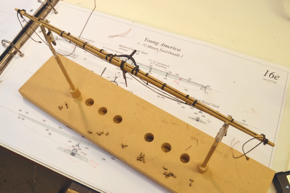
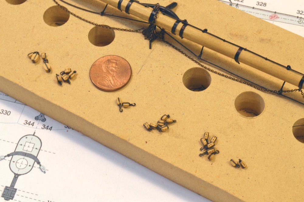
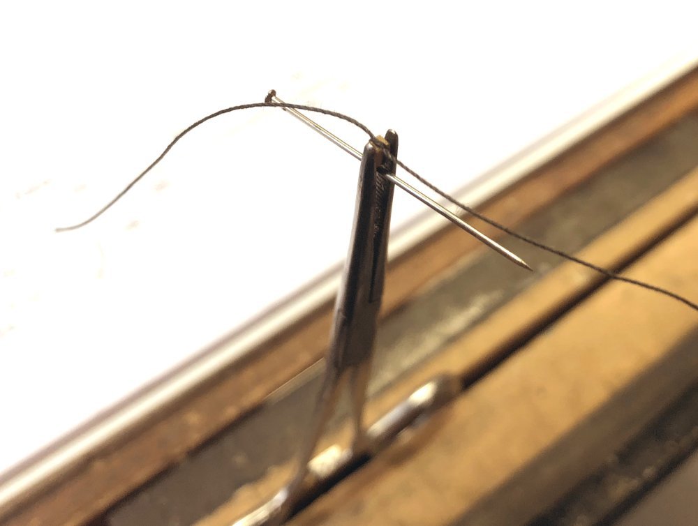
Young America - extreme clipper 1853 Part 297 – Crojack Yard 2 The first picture shows the crojack yard set up in the fixture used for rigging. The footropes, topsail yard sheet chains, topping lift pendants, and reef tackle yardarm blocks have been installed. The blocks for this yard that remain to be installed have been strapped and are shown on the fixture base ready to be lashed on. Altogether, there are 30 blocks associated with this yard – not the most or least for a yard but perhaps an average for the 18 yards. The next picture shows a closer view of these blocks. From left to right, these are: 2 assemblies of shackled sheet and clew garnet blocks, 4 triple blocks for the topsail sheet tackles, 2 iron-strapped, hooked, double quarter blocks, 4 + 2 spare bunt line blocks that will be lashed to the jackstays, 4 + 2 spare of these to be hooked under the crosstrees, and 2 reef tackle blocks that will be tied off to the jackstays. Except for the two 11" sheet blocks, all are 8". The next picture shows the method I use for the simplest strapping configuration – a strap with a single eye. Strapping line, about 1/3 in size to the size of the block, is first tied in a double overhand knot around a pin to form the eye. With the block held in a surgical clamp, the splice at the base of the block is formed with a single overhand knot. The pin left in the eye is helpful in centering the eye on the top of the block when tying the splice. The splice and the top knot are then brushed with diluted dark glue. This simple method works well for small blocks – and is easy – especially helpful if you have 100's to do. The next picture shows the sheet/clew garnet block assemblies before cutting off the excess strapping. For these, the eyes were first tied around the shackles then spliced below as described above. The shackles are large enough to handle the eyes of the sheet, tack and lazy tack – to be shown later. In the next picture all the lashed blocks have been installed. The last picture shows the attached blocks on one side. Below the yardarm is the reef tackle block lashed to the lower collar eye. The topping lift pendant is shackled to the top eye and dangles behind the yard. The brace pendant, will later be shackled to the forward eye on the collar. From the left, just inside the clamp, the first block fixed to the jackstay is the other reef tackle block – tied with hemp since this is cut free and fixed the sail when it is set. The next two on the jackstay are the permanently lashed bunt line blocks. Next, hanging below the yard, is the hooked iron strapped quarter block. The loop of chain below the iron sheet block will have the triple tackle blocks shackled and the chain separated into two falls later. Ed
- 3,618 replies
-
- 24
-
-
- young america
- clipper
- (and 1 more)
-
Thanks, again, everyone. We'll see about the spreaders when all 3 pair of backstays are rigged, Harvey. I do believe they will be well restrained in the up-down direction, but will the stays tend to pull them inward? We should soon find out. Ed
-
Wow, that is impressive progress - and beautiful work. I look forward to seeing more of your model and learning more about you as well. Good luck with the project. Ed
- 3,618 replies
-
- 2
-
-
- young america
- clipper
- (and 1 more)
-
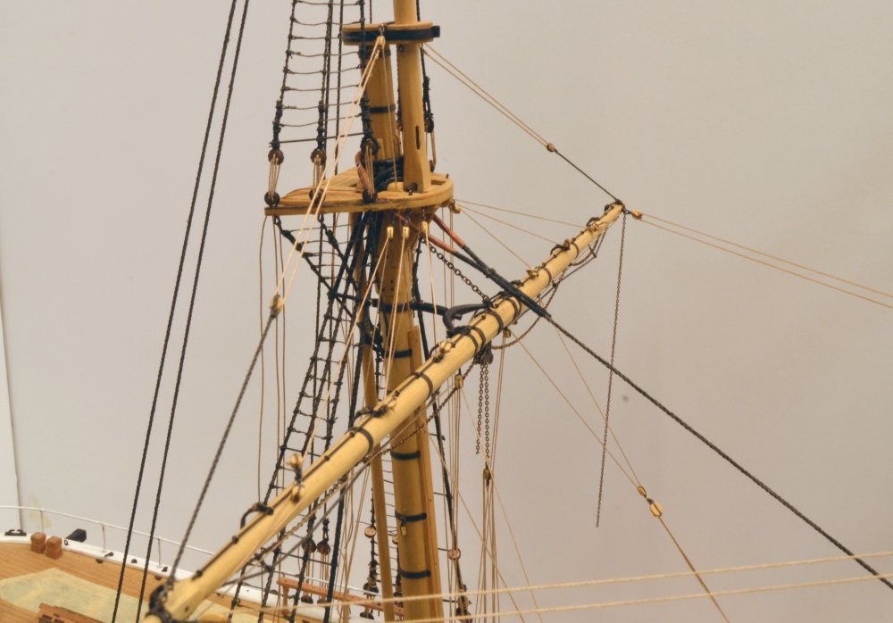
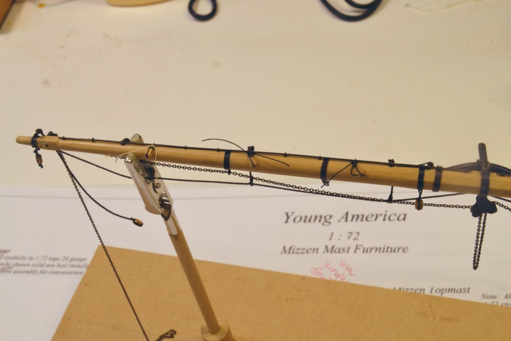
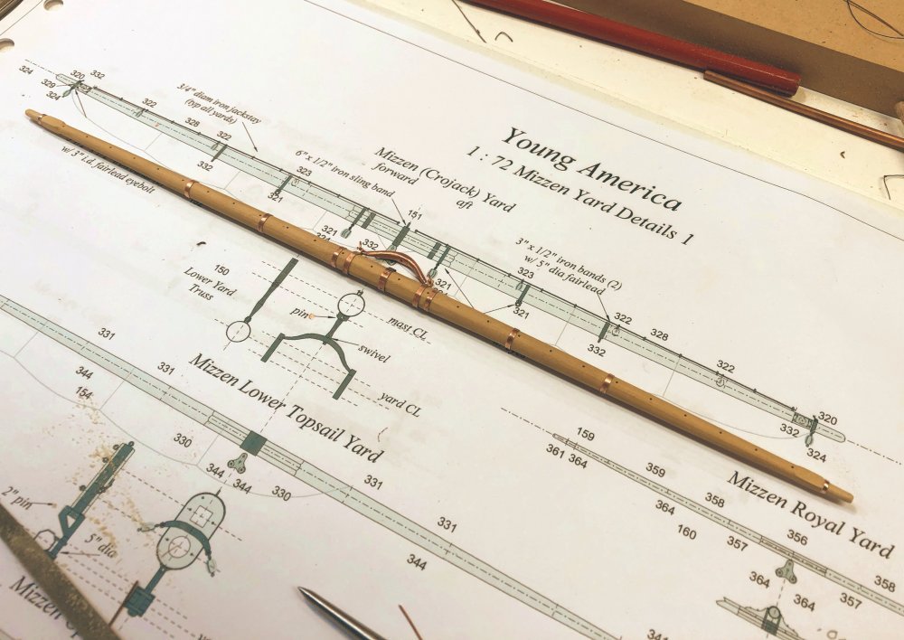
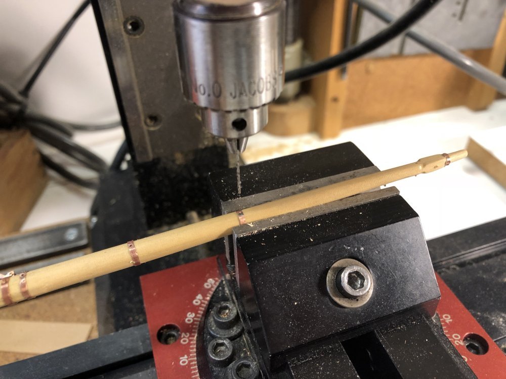
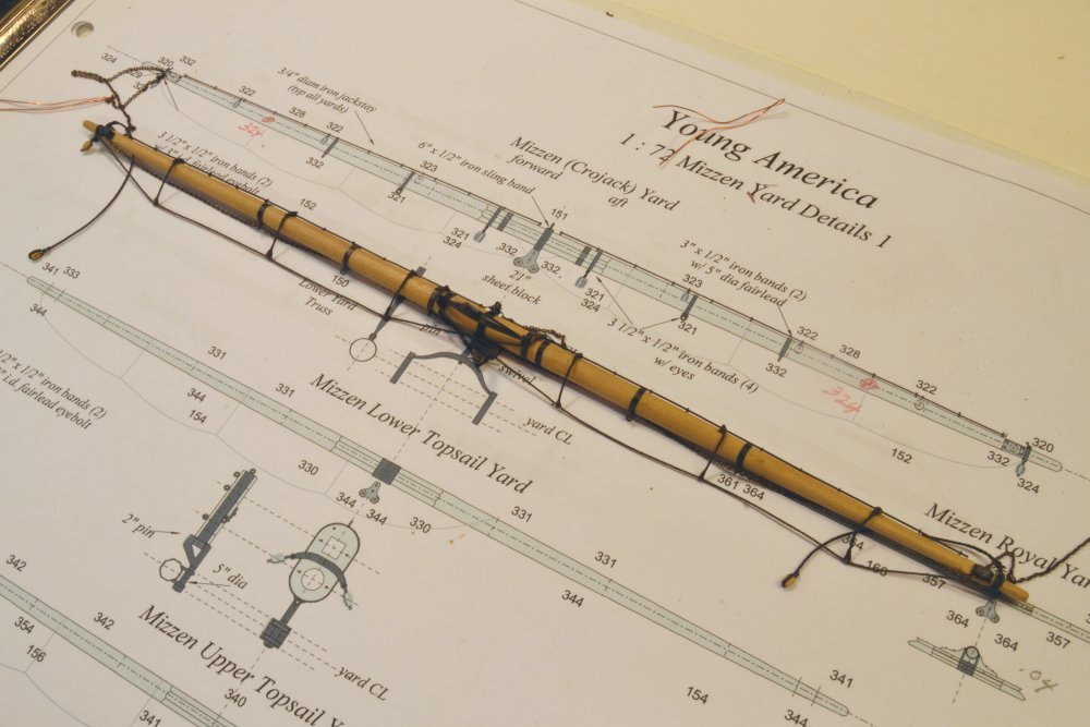
Young America - extreme clipper 1853 Part 296 – Crojack Yard 1 The lower mizzen sail was a late development, but common on the fast clippers. Its unique name, crossjack, more commonly "crojack", pronounced "crojick", was devised to distinguish it from the lateen yard of earlier days, previously called the mizzen yard. The term crossjack may have derived from the run of its braces. These ran forward toward the center in a V to pendants on the mainmast – rather than aft to belay at the sides. Other than that, the yard is much like the other two lower yards. The first picture shows the yard with its bare copper banding and part of the truss assembly installed. Since the mizzen carried no studding sails, this yard had no boom irons – a welcome omission to the modeler weary of making these complex metal fittings. The next picture shows the yard temporarily mounted by its truss. Once returned to the bench, the jackstay stanchions, 28 gauge copper wire eyebolts, were pushed into the holes atop the yard. Before blackening all this copper, holes for the various eye bolts were center-marked and drilled. Drilling the small yardarm bands requires care, since each has three holes. In the next picture the ironwork has been blacked, the jackstays slipped in and the yard again mounted temporarily. Blackening of the ironwork, using liver of sulfur solution while rinsing the yard under running water was discussed earlier. The next picture gives a better view of the truss. With the mounting shown above, the length of the length of the chain sling assembly may be measured and the hole for the mast eyebolt drilled. The sling assembly consists of a yard eyebolt, a shackle, chain and a mast eyebolt. In the next picture, this assembly plus other rigging has been added to the yard. The standing rigging on these lower yards consists of the chain sling and the 4½" footropes with their 4" stirrups. The topping lift pendants and one of the reef tackle blocks suspended from the yardarms may be seen in this picture. Less visible, but also present, are the chain sheets for the lower topsail yard and the central iron sheet block. Before setting this yard, blocks for all the running rigging will be added – next post. Ed
- 3,618 replies
-
- 35
-
-
- young america
- clipper
- (and 1 more)
-
A masterful job, Micheal, from start to finish. An encyclopedia of interesting problems and innovative solutions. Bravo. Ed
- 749 replies
-
- 3
-
-
- albertic
- ocean liner
- (and 2 more)
-
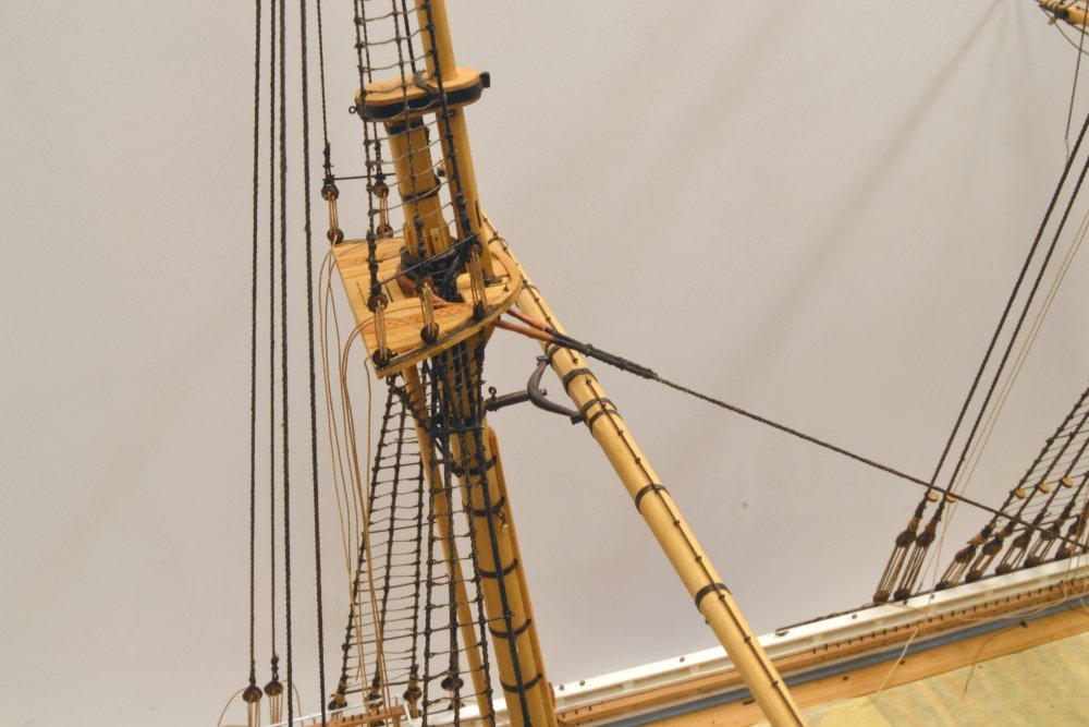
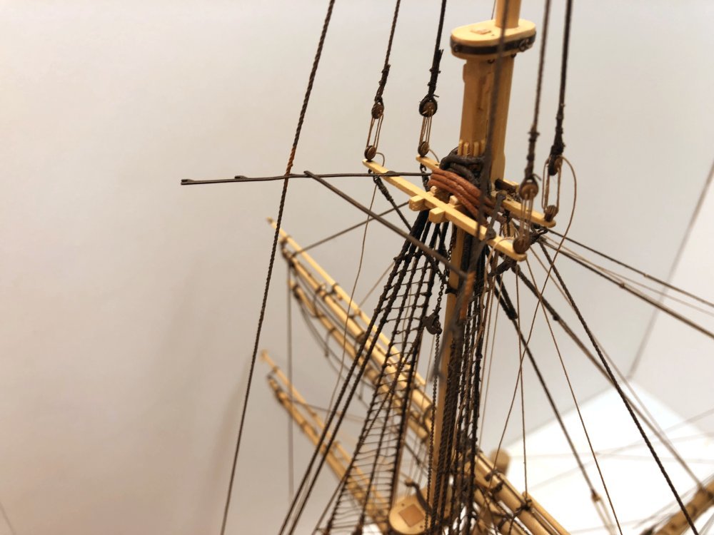
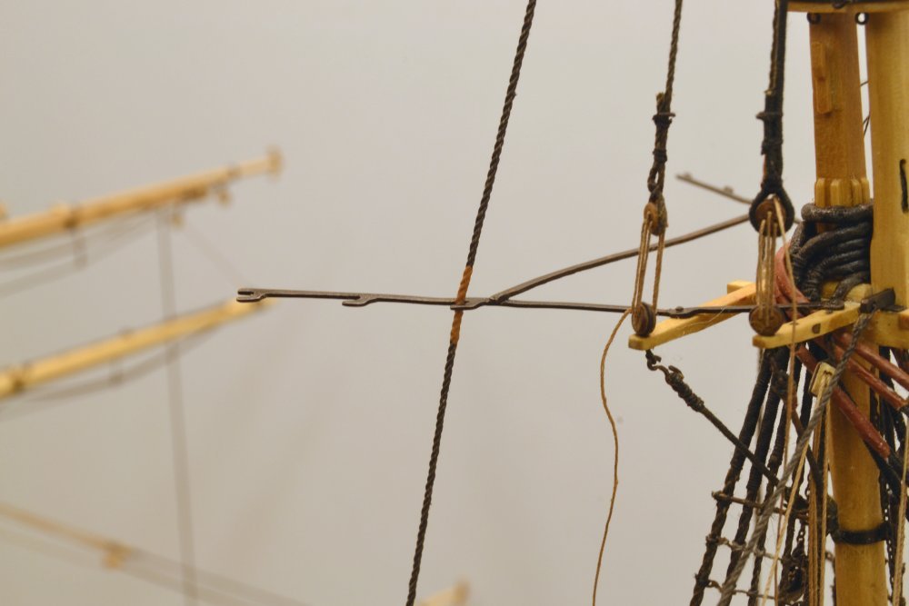
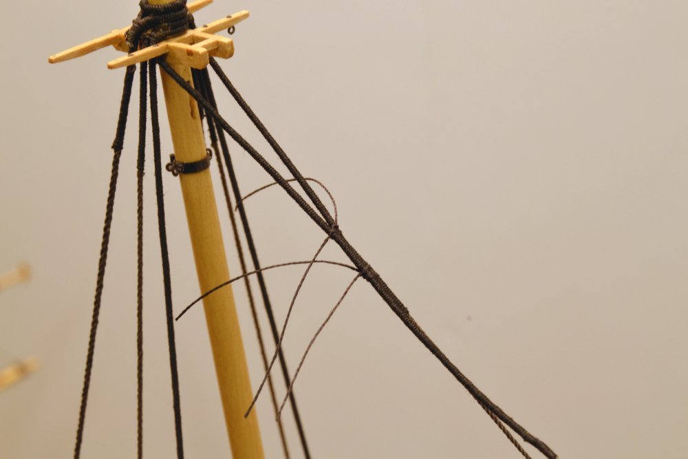
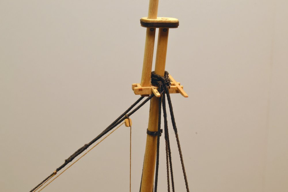
Young America - extreme clipper 1853 Part 295 – Topgallant Backstays Progress continues to be sporadic as the summer wanes and other unfinished items on the season's household do-list demand attention. I am down to an average of an hour or so a day on the model this month, so there have been fewer posts. This one is short, showing only the fore topgallant backstays mentioned in the last post. The first picture shows the two lines installed with white arrows pointing them out in an increasingly dense array of rigging. The two 7" stays go over the masthead after the shrouds - as is normal. They are guided through cleats on the iron spreaders that extend aft from the topmast crosstrees. The next picture shows the spreaders with the backstays threaded through. The stays were leathered in the way of the spreader cleats to reduce wear. The next picture shows this simulated with brown acrylic paint. I expect to finally straighten the metal spreaders as the three sets of backstays are rigged. The stays should help prevent bending, which up to now has been a problem. Note that the topgallant shroud lanyards remain loose pending final tensioning of all the topgallant standing rigging. This is also apparent in the last photo showing the deadeye/lanyard arrangement on the starboard channel. The two remaining smaller deadeyes on this channel will support the royal and skysail backstays. Other current work includes some upper yard fabrication as well as fitting out and rigging of the mizzen lower yard – the crojack. That will be described in the next post. Ed
- 3,618 replies
-
- 33
-
-
- young america
- clipper
- (and 1 more)
-
Thanks for all these comments and likes - very much appreciated. Let me address some comments. Frank, there seems to be as much planning and preparation as there is actual work. All should be revealed if I can manage to complete the model and get Volume III written. The short version is that a very detailed "rigging list"is the heart of the process. There are far too many lines to show on a large drawing or even more than one. The 21 page list contains all details of each line including routing. Line numbers on the list are also placed on detailed drawings of all spars, structures and on a belaying plan. There are around 350 line numbers, many representing multiple lines - like shrouds (6 pr/line no.) or bunt lines (2 pr/line no.). Some lines like halyards are part chain, part rope and part wire. Many lines have multiple parts - eg. pendant+tackle+fall. The list will of course be part of the book. I prepared the list and related information based on contemporary data from several 19th century sources, Underhill's book, Crothers YA plan. The list should be applicable to most ships of this class. Pat, I suppose that small scale rigging - like most modeling - involves compromise in level of detail. Shortcuts acceptable at 1:72 would not look good at 1:48 or 1:32. Those scales require much more meticulous modeling of each component - not my forte. Scott, in these posts I did not say much beyond a brief comment about making or staining rope. I stain running rigging (hemp color) with a walnut extract stain, diluted to the desired color. This non-fading, water soluble stain was made using "Van Dyke" crystals made from natural walnut extract. After making and stretching the cotton or linen rope - or just using cotton thread on small lines - I drag the line through a container of stain and hang it up straight to dry. When dry, I de-fuzz it through the flame of an alcohol burner - two passes, then wind it onto a spool. Same for standing except substitute diluted India Ink. Ed
- 3,618 replies
-
- 12
-
-
- young america
- clipper
- (and 1 more)
-
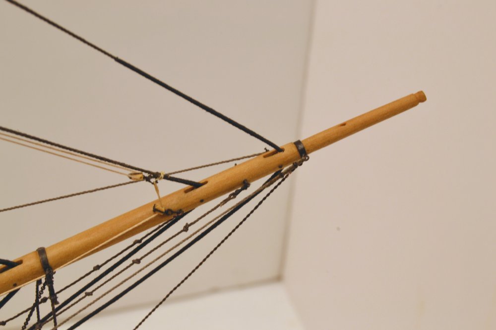
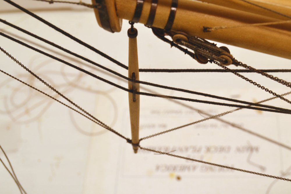
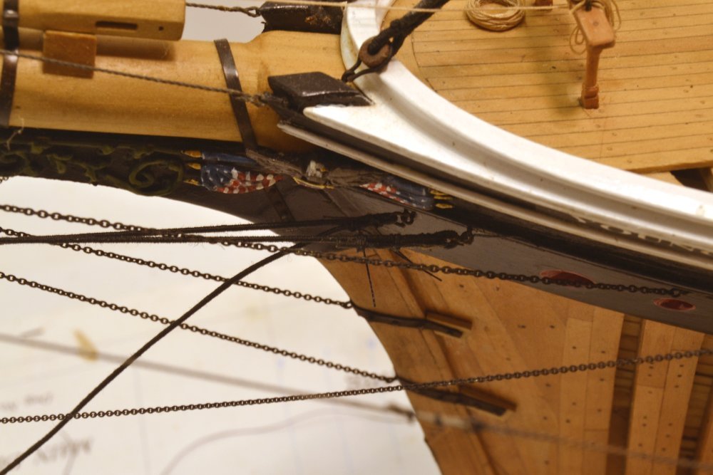
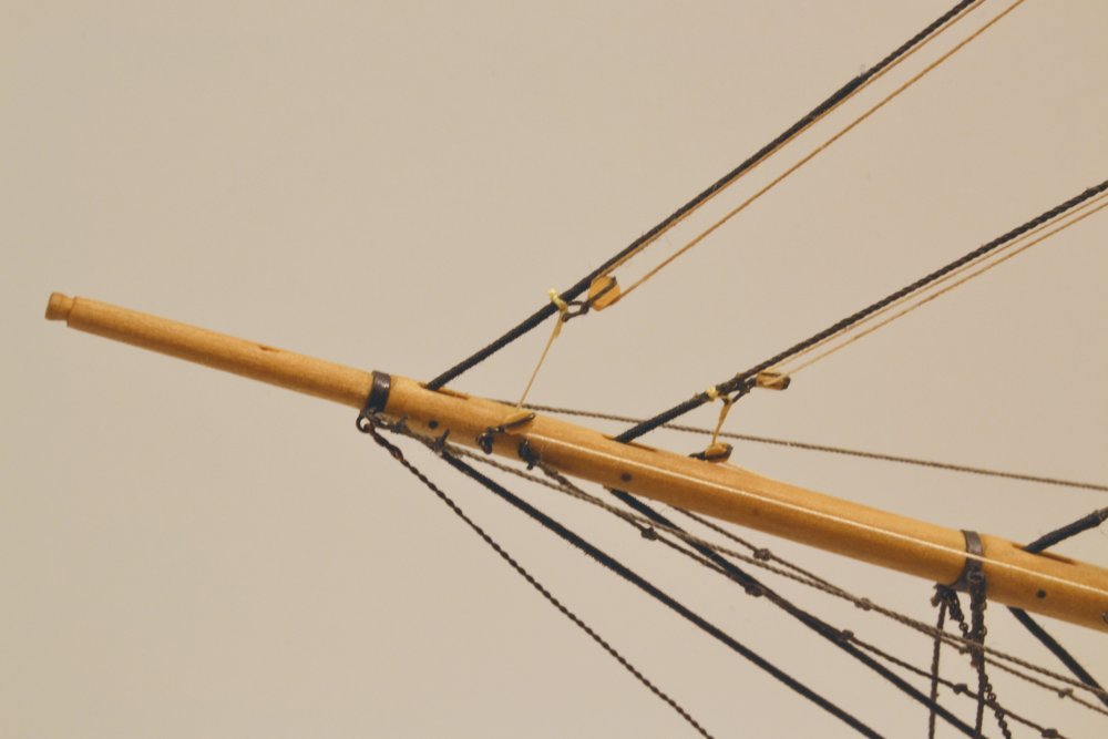
Young America - extreme clipper 1853 Part 294 – Flying Jib Stay In the last post, I mentioned that I had gotten out of sequence by installing the fore topgallant shrouds before the forward stay – also known as the flying jib stay – so this had to be slipped under the two pairs of shrouds. In the first picture the seizing on the stay collar have been put on but not yet trimmed. Both the upper and lower ends of this 5" stay are served. When the diluted glue on the seizings and short served end has dried, the excess rope will be clipped off. At the lower end the stay passes through a sheave in the flying jibboom as shown in the next picture. The serving extends from above the boom over the entire remainder of the stay. The stay then passes through the lower cleat on the port side of the martingale as shown in the next picture. Finally the end is secured with seizings to a shackled eyebolt in the hull – just below the flag in the next picture. Again, the loose ends will be clipped off later. As its name implies, the stay supports the flying jib. The next picture shows running rigging for this sail tied off to the lower end of the stay. The jib halyard passes through the block shackled and tied to the stay in this picture. The downhauler is attached to the shackle, passes through a block hooked to an eyebolt on the spar and then runs back to belay on the forecastle pin rail. The shackle shown in the picture is tied off temporarily to the stay. When the flying jib is bent, this shackle, with both lines, would be connected to the head cringle on the jib. The tack cringle at the lower end would be made fast to the lower stay. Hanks would be placed along the luff of the sail, connecting it to the stay. The jib could then be hauled up with the halyard and back down by the downhauler. At the upper end of the stay the halyard passes through a block lashed to the stay as shown in the next picture. The standing part of the halyard may be seen tied off to the stay below the serving in this picture. From the block shown, the line runs down along the mast to the foremast fife rail, most likely making this 2½" rope the longest in the ship. The last picture shows the model with the stay and flying jib rigging installed. The topgallant backstays may also be seen in the picture. I will describe those in the next post. Ed
- 3,618 replies
-
- 40
-
-
- young america
- clipper
- (and 1 more)