EdT
-
Posts
2,214 -
Joined
-
Last visited
Content Type
Profiles
Forums
Gallery
Events
Everything posted by EdT
-
HMCSS Victoria 1855 by BANYAN - 1:72
EdT replied to BANYAN's topic in - Build logs for subjects built 1851 - 1900
Wonderful work, Pat. I love the hammock railing - neat as a pin. Ed- 1,013 replies
-
- 4
-

-
- gun dispatch vessel
- victoria
- (and 2 more)
-
Thank you, Daniel. It is a pleasure to hear from beautiful Bergamo that I have visited a number of times when on business in Mozzanica. I am reminded of it whenever I open a bottle of San Pellegrino. Cheers, Ed
- 3,618 replies
-
- 1
-
-
- young america
- clipper
- (and 1 more)
-
HMS ANSON 1781 by albert - 1/48 - 64 guns
EdT replied to albert's topic in - Build logs for subjects built 1751 - 1800
The beginnings of another masterpiece I am sure, Albert. I look forward to your progress as always. Ed -
Catching up again, Frank. Love the meticulous attention to detail - and the methods. Bravo. Ed
-
Beautiful work as always, Chuck. Ed
- 421 replies
-
- 4
-
-
- medway longboat
- Syren Ship Model Company
- (and 1 more)
-
Thank you, Druxey and Pat and to those who "reacted" with a like. So, Druxey, the short answer to your question is - I don't know. But, as usual, there is more. My usual 19th century sources , Luce, 1868 and Murphy and Jeffers, 1849, are clear that the forward tg stay goes over first, but without explanation. The latter of these as well as Underhill, who agrees, describe the stay with an eye splice to fit over a masthead strop on a pole mast. Since I am modeling the masts per Webb's original plan, that is, stepped up to the royals, the eye splice is probably not appropriate. Crothers shows a seized collar like the lower stays on his plan, which follows Webb's stepped upper masts. I have adopted this method with the stay going on first. One could debate the order on this arrangement, but that is the choice I made. I wrote up the rigging notes based on that, then overlooked them in my haste to get on - typical, but an easy fix. Pat, I agree that some rigging tasks are chore-like, for example ratlines, or making rope coils, but others can be quite interesting, especially if you think of each line from an operational view. Cheers, everyone. Ed
- 3,618 replies
-
- 6
-
-
- young america
- clipper
- (and 1 more)
-
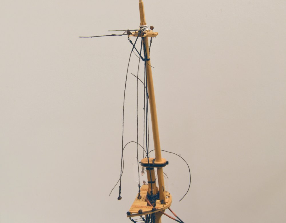
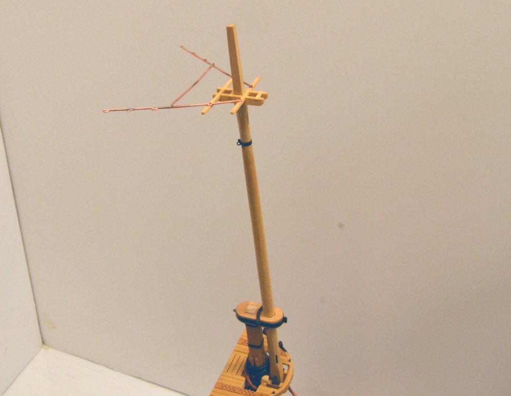
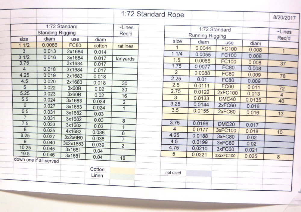
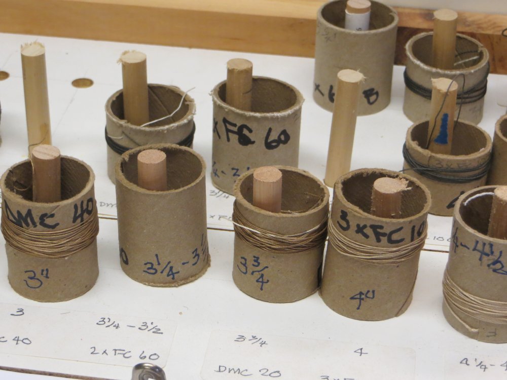
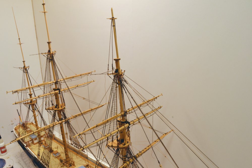
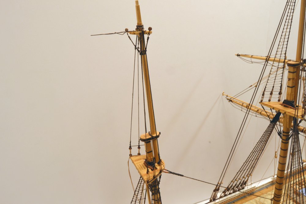
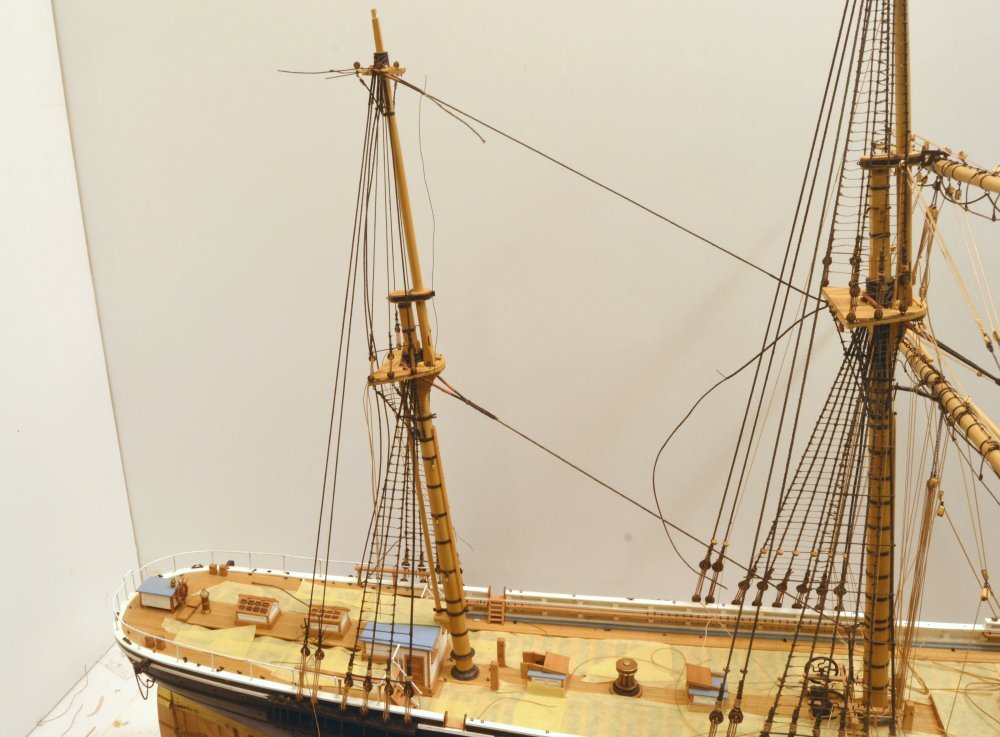
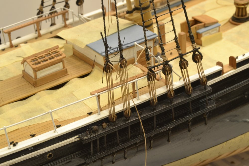
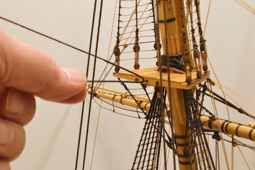
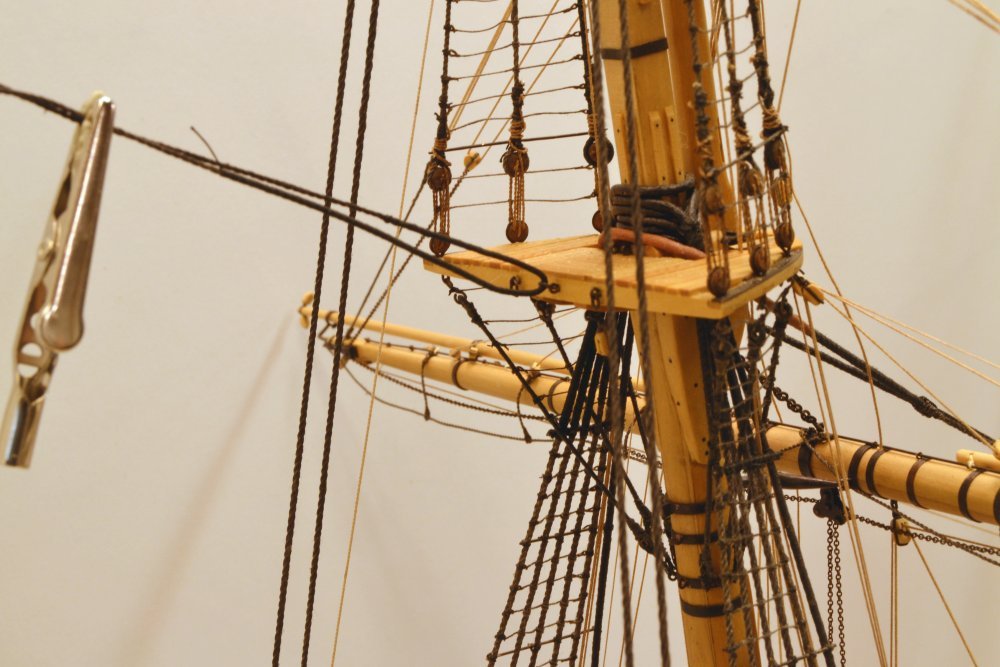
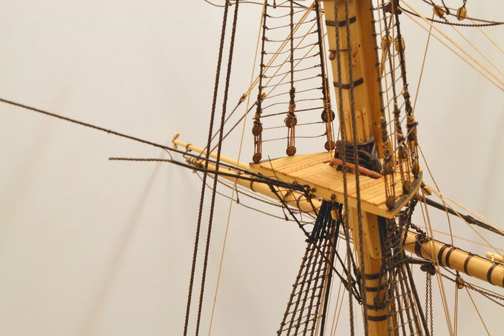
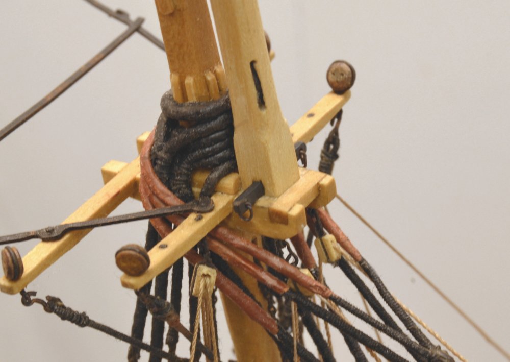
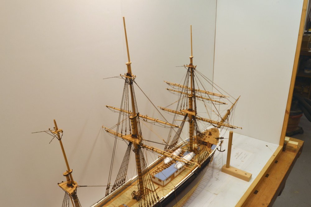
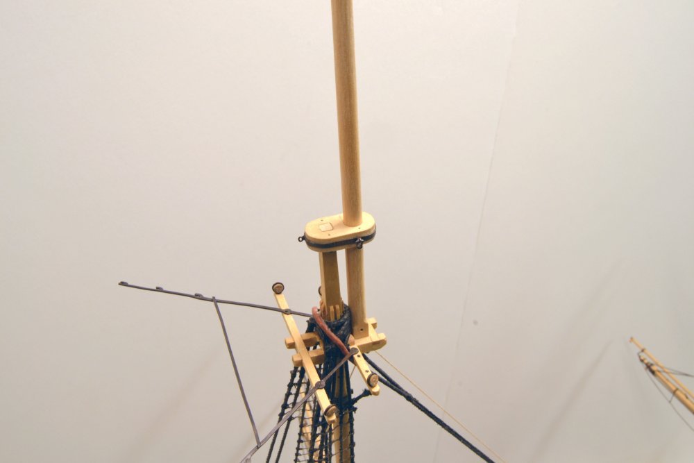
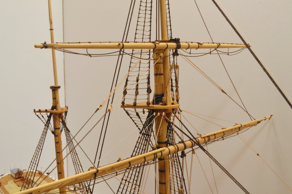
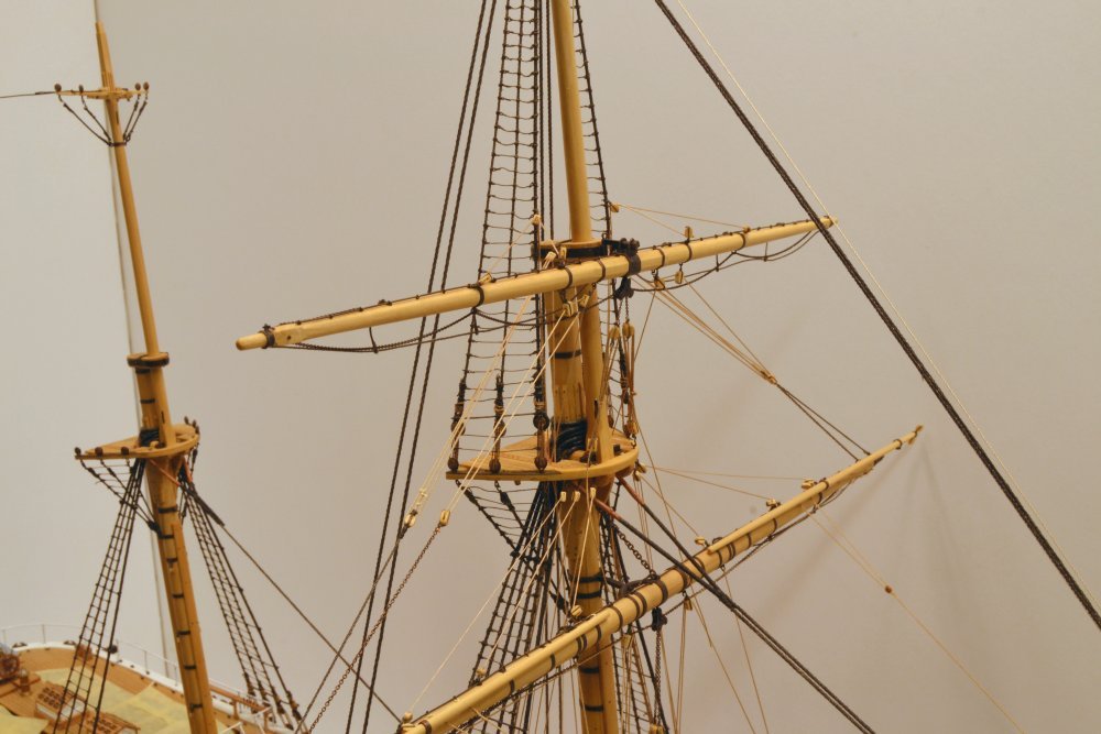
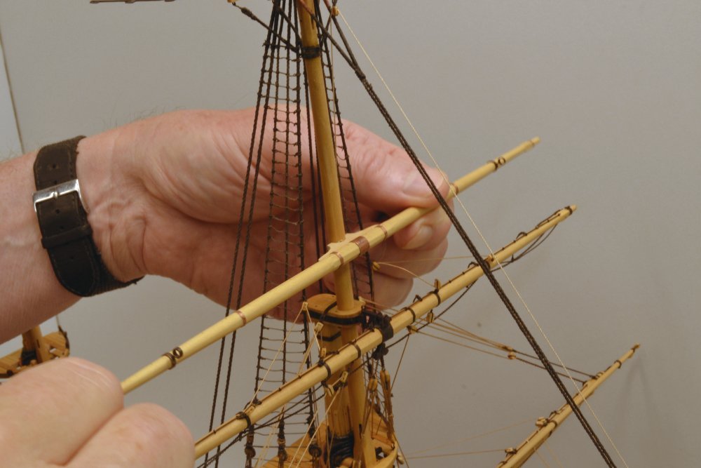
Young America - extreme clipper 1853 Part 293 – Fore Topgallant Mast Work continues to go slowly this summer. Much of it is repetitive, so there is not always something new to report. After the last post there were some interesting comments on rope sizing, so I included a couple pictures of things I use to simplify the selection and sizing process. The fist photo shows a table – an Excel spreadsheet actually – that tabulates 1:72 scale rope sizes and makeup. I generally use linen for standing rigging because it stretches less and is stronger than the cotton I use for most of the running rigging - and occasionally for some standing lines. The left table is for standing and the right for running. Green indicates linen and yellow for cotton. The left column on each table is rope size (actual circumference in inches). Next to the right is its 1:72 diameter, then the thread makeup for each size showing number of threads and thread designation, then the diameter of the model rope. The last column is a rough count of lines for each size, but this is not used much. Line is made on an as-needed basis. Creating this table involved making rope from different thread combinations, measuring the rope and then assigning sizes and creating the tables. The next picture shows line on spools marked with rope size and makeup. Rope is put on these spools after dyeing and de-fuzzing. There are two sets of spools, - one for standing and one for running. Sizing is not always precise, so some judgement is applied when selecting rope. This all involved a lot of work up front, but once done selection is quick and easy. So, back to the work. The first picture shows the overall state of the model at the time of this post. In the picture the three lowest yards have been installed and mostly rigged on the main and fore masts. The fore topgallant mast has been permanently set and the upper main and mizzen masts are temporarily placed. The next picture shows the fore topgallant mast just before lowering to its final position. Iron plates under the fid were slipped in and glued with some CA just before lowering the mast on to the trestletrees. In the next picture the mast is set and the starboard shrouds have been fitted. The lanyards are left loose for final tensioning. At this stage, with the fid installed, the standing lifts for the upper topsail yard could be rigged. The picture shows eye splices on these shackled to the fid eyes on either side. Fid shackles were discussed in an earlier post. The next picture shows the fastening of the lift at the starboard yardarm. I am securing these to the upper eyes on the yardarm band with hooks on eye splices – a common method that probably preceded shackles. I am using both methods, reflecting a likely evolution in practice at the time. These could also be shackled. Standing lifts were used on all yards above the lower topsails. Lower yards had topping lifts and the lower topsail yards had no lifts. When under sail, with the yards raised, the standing lifts draped loosely behind the yard. On the model, all yards will be lowered with the lifts taut, as would be normal in port, with no sails set. The last picture shows some corrective work involving threading the topgallant stay under the already installed shrouds – the result of a small oversight in fitting the shrouds first. For some reason, the forward stays on the topgallant masts were the first lines to go over the masthead, unlike on the masts below, where they go over last. I had the correct order in my rigging list, but overlooked it. So, in the above picture, the stay was threaded under the already installed shrouds. I will cover the installation of this line and the topgallant backstays in the next part. Ed
- 3,618 replies
-
- 34
-
-
- young america
- clipper
- (and 1 more)
-
I use a simple method for quickly selecting the correct rope size, which in my case is specified on the rigging list in the actual (inches circumference) for each line, lanyard, pendant, etc. Once the right size model rope is assigned - either made rope or right off the thread spool for small lines - the model rope is dyed (black or hemp) and put on spools marked with the actual rope size. All the calcs, spreadsheets and tables were done once. I'll put a picture in the next post. Ed
- 3,618 replies
-
- 4
-
-
- young america
- clipper
- (and 1 more)
-
Too complicated for me, Greg. Reminds me of the circular slide rule I always carried in my shirt pocket 50 years ago - before going digital. Ed
- 3,618 replies
-
- 2
-
-
- young america
- clipper
- (and 1 more)
-
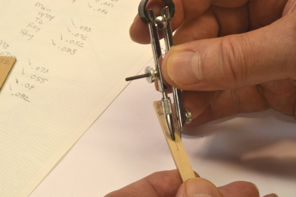
Thanks for the comments and thank you for your explanation wefalck. Measuring rope by circumference is as old a ships, I believe. Certainly all the rigging tables from earliest times adopt the method, so that one becomes used to it. I believe it would have been most convenient for early riggers and others to measure a rope with a length of string - perhaps knotted at intervals. The use of even crude calipers would be unusual and certainly not as convenient as a length of string in one's pocket. I measure rope diameter using digital calipers over a length of 10 tightly wrapped turns of rope on a dowel, then divide by 10 and multiply by 3.14 and then 72 to get rope size - or reverse the process to get the desired model size.. A calculator is a frequently used tool in the shop for this and many other tasks. Pat, I have not found - or looked very hard - for actual real life specs for the number of seizings. Based on various diagrams and drawings, my made-up rule seems reasonable. I wanted some guideline to follow for this - and to provide for future readers - and this seemed reasonable - and hopefully not controversial. So, the big 11" stays have four, the 8" stays in the post three, and for small lines a minimum of two - or perhaps an overhand slip knot with one. Ed
- 3,618 replies
-
- 4
-
-
- young america
- clipper
- (and 1 more)
-
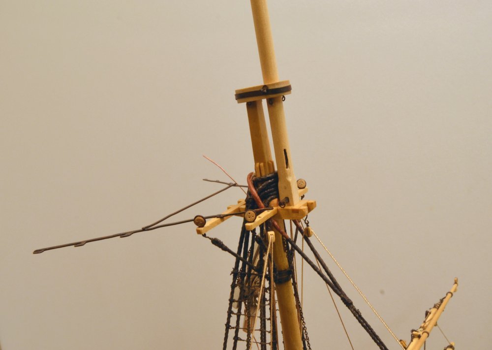
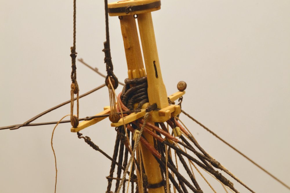
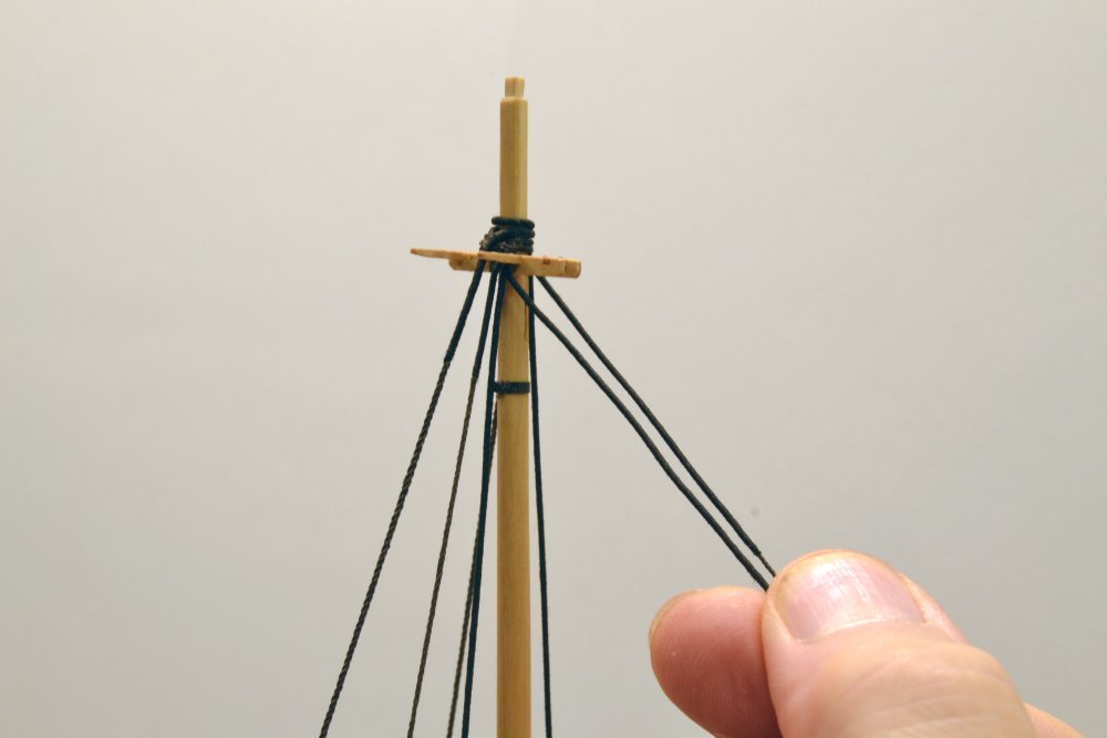
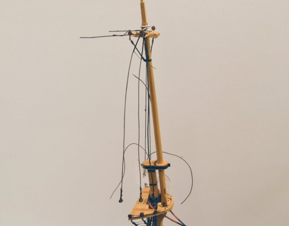
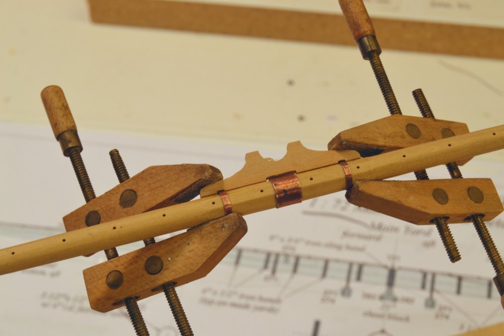
Young America - extreme clipper 1853 Part 292 – Mizzen Topmast Standing rigging It has been a few weeks since the last post. Busy summer, but work has been proceeding to the tune of one or two hours a day. The work in this post was completed in early July. The first picture shows the mizzen topmast set in position with some of its standing rigging fitted. The futtock shrouds for the topgallant mast shrouds were put on before the mast was set – as described for other masts in earlier posts. In this picture the six topmast shrouds were temporarily put over the masthead to allow the glue on the parceling to dry. The seizings were then tied. The serving ends have still not been clipped off. The deadeyes have been turned in on the starboard side. The next picture shows further work on the shrouds. The parceling has been "tarred" with black acrylic paint, the deadeyes have been threaded and given an initial tension, and staves have been lashed on top and bottom. These were made from stiff blackened brass wire. Drawn boxwood staves that were used on some of the earlier rigging have proved too fragile and most of these have been replaced with wire. The next picture shows the backstays rigged and the mizzen topmast stay seized at the top collar and loosely fitted. On all the masts the topmast backstays are the same size rope as the lower shrouds. This was discussed in an earlier post. These seemingly large sizes were mandated by the underwriters at the time, probably due to mishaps caused by overly aggressive captains. The backstays go over the masthead after the shrouds and before the forward stay. In the picture the starboard backstays have been secured. The next picture shows the lower ends. The lengths of the backstay lanyards are longer than those on the lower shrouds to allow for more tightening of these longer, structurally important lines. The excess seizing ends will need to be clipped off. The lanyards are left loose to allow additional later tensioning. This progressive tensioning has been necessary on all standing rigging. The next three pictures show the method used to secure the lower end of the mizzen topmast stay. This stay cannot be secured before at least the initial tension is set on the backstays. The top end of the stay has the typical collar – served, parceled, leathered and the seized below the crosstrees. The forward connection shown above is made with a seizing through a shackled eyebolt on the main mast top. In the picture the stay is being pulled through the shackle and hauled tight. The lower end of this stay is served. In the next step the stay is clamped as shown in the next picture before applying the seizings. In the next picture the seizings have been applied. I am using a rule-of-thumb of one seizing for every 3" of rope size – rounded up – so there are three seizings on the 8" stay. Rope size is circumference. After tying, the seizings as well as the served short end, are soaked with thinned, darkened glue. The excess ends are then clipped off when the glue dries. The final tension of this stay is set by hauling on the four backstays and the topmast shrouds. Ed
- 3,618 replies
-
- 27
-
-
- young america
- clipper
- (and 1 more)
-
Thank you all for these comments. I have been away lately and have not been keeping up very well, so I am late in some replies. Mike, I find that isopropyl alcohol does a good job degreasing and cleaning away any residual copper dust, but I have also observed that liver of sulfur does not require as much cleaning as the selenious blackeners like Brass Black or Hobby Black. Maury, food coloring is interesting because it is likely to be vegetable dye and therefore probably non-fading. Have never used it. Calhoun, thank you for your endurance in reading through the thread - as evidenced by the volume of notifications recently. Sorry for the nautical vocabulary. I am anything but an old salt, but in developing the rigging list for the model and through using it everyday in the work, the labels stick. Clippers, large ships designed for long voyages across the globe, and specifically those destined for regular Cape Horn service had to be built very strong - and so they were. Ed
- 3,618 replies
-
- 4
-
-
- young america
- clipper
- (and 1 more)
-
I have not tried India Ink to darken glue, but use it for other dyeing because it is non-fading - as is the dry pigment. India Ink does contain a binder, usually shellac, to make it waterproof after drying. The binder may affect the PVA glue. The best answer for this is to test glued parts with and without the coloring used. Make some identical wood samples, glue them, then pull them apart.
- 3,618 replies
-
- 1
-
-
- young america
- clipper
- (and 1 more)
-
Lawrence, The problem with adding an acrylic to the PVA glue is that it will very likely affect the glue strength - and not in a good way. The artists pigment has shown no ill effects on the properties of the glue. I suggest ordering it online from an artist supplier - perhaps Jerry's Artarama - link below. I use burnt Umber. I described the mixing process both in the Naiad Volume I and in the Young America Volume I. https://www.jerrysartarama.com/sennelier-artist-dry-pigments Good luck, Ed
- 3,618 replies
-
- 1
-
-
- young america
- clipper
- (and 1 more)
-
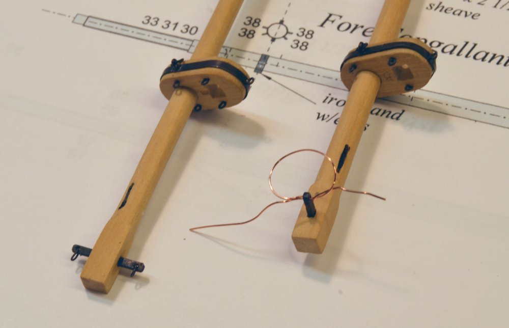
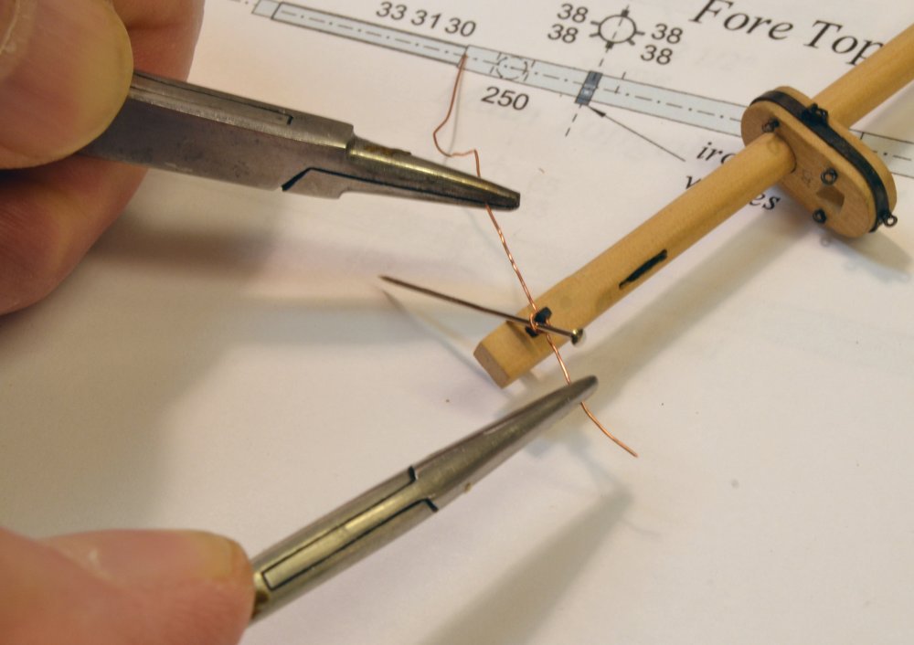
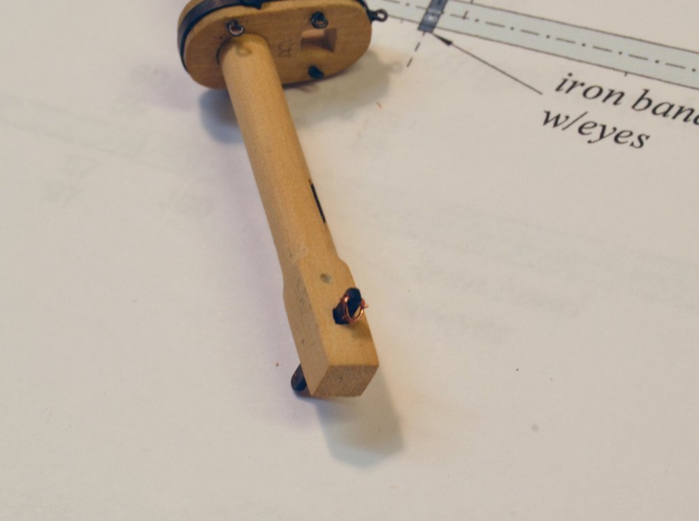
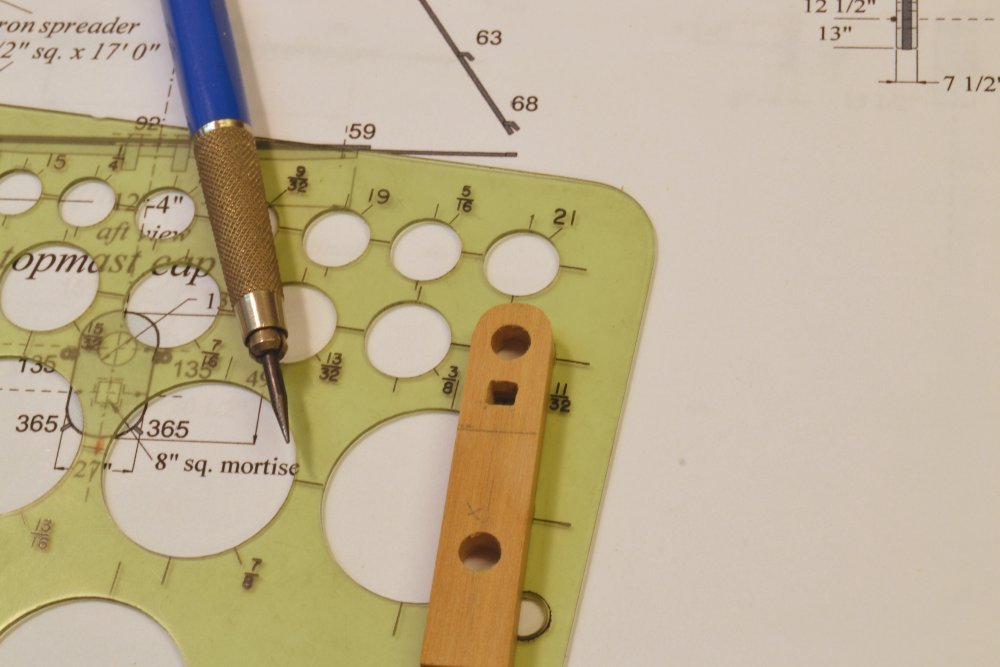
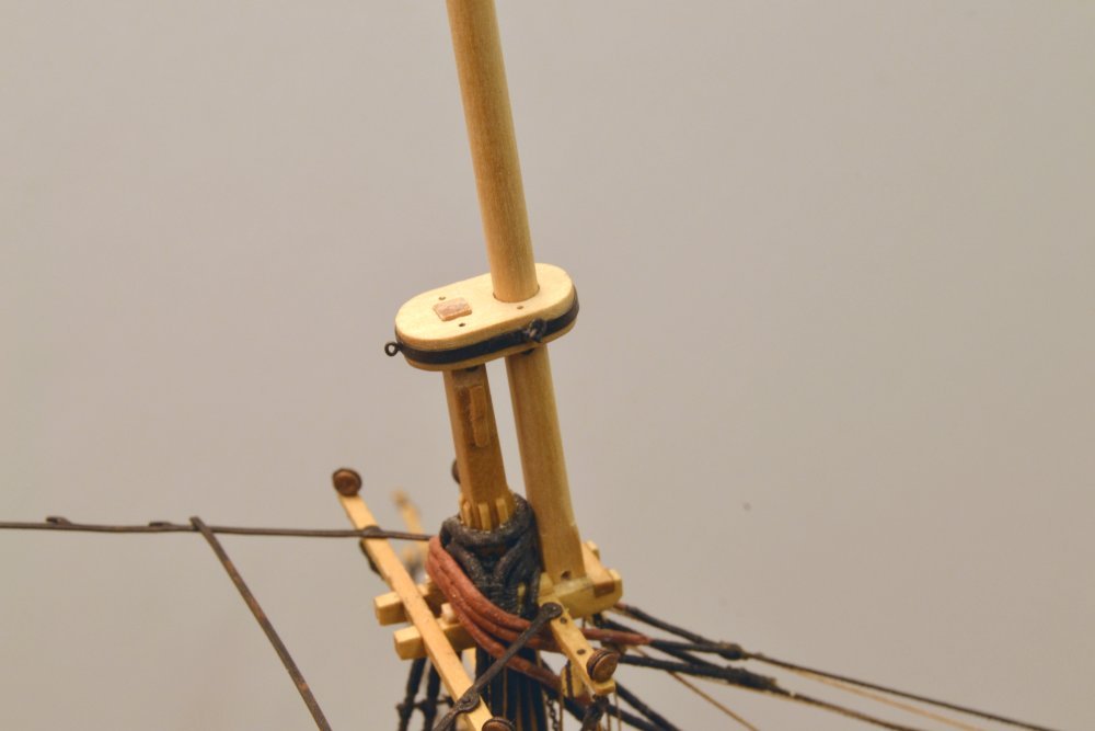
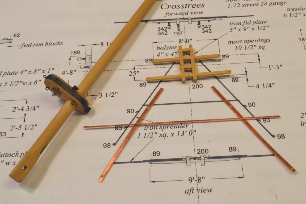
Young America - extreme clipper 1853 Part 291 – Upper Mast Fids Young America's upper masts would have been supported on iron fids that passed through a rectangular mortise near the base of the upper mast. The fid then rested on the trestletrees. Masts were hauled up through the forward opening in the top or crosstrees, the fid slipped in, and the mast lowered into place. Fids on the topgallant and royal mast sections had horizontal holes bored in the ends for shackles that held the standing lifts for the upper topsail and topgallant yards respectively. The base of one of the topgallant masts with its fid shackles is shown in the first picture. Most shackles like this would be shaped and the bolts soldered to the yokes off the model – an impractical solution on these fids that had to slide through the tight mast mortise. My initial idea was to solder the shackles then cut the fid in the center and insert it from both ends – using CA glue to anchor the two pieces. However, other situations arose where shackles had to be formed in place on the mode, so a different method was adapted for those and for the fid shackles. The next picture shows a finished fid – on the left - with shackles fitted. Because the model masts are inserted from above, the fids may be inserted before setting the mast. The mast at the right in the picture shows a shackle in the process of being formed. To make the shackle, ends of a length of wire were inserted through the fid eye from opposite ends. An overhand knot was then tied in the wire as shown. The wire was then pulled tight as shown in the next picture. The overhand knot becomes hidden in the fid hole. The pin was used to maintain an opening in the yoke of the shackle. Once the wire was pulled tight, the ends were clipped off to form the final shackle shown in the last picture. This method has also been used on a number of in situ chain connections and wherever a shackle is required but not able to be pre-soldered. Shackles made in this way look realistic at this scale and are quite strong – more than strong enough for the tightest rigging. Shackles on these fids and at the yardarms allowed standing lifts to be made with spliced eyes at each end. Later. Ed
- 3,618 replies
-
- 36
-
-
- young america
- clipper
- (and 1 more)
-
Hi Micheal, Any water-based finish is likely to be have an adherence problem on unprimed metal. Suggest a solvent-based primer for metals first. Your spray booth probably doesn't catch solvents, so you may wish to spray the primer outdoors. Ed
- 749 replies
-
- 6
-
-
- albertic
- ocean liner
- (and 2 more)
-
Thank you, Pat. The work is non-sequential and somewhat piecemeal these days, so I am drifting into a one-post-a-week mode. Ed
- 3,618 replies
-
- 6
-
-
- young america
- clipper
- (and 1 more)
-
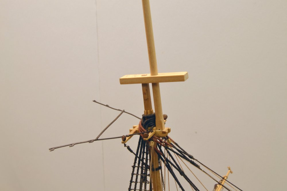
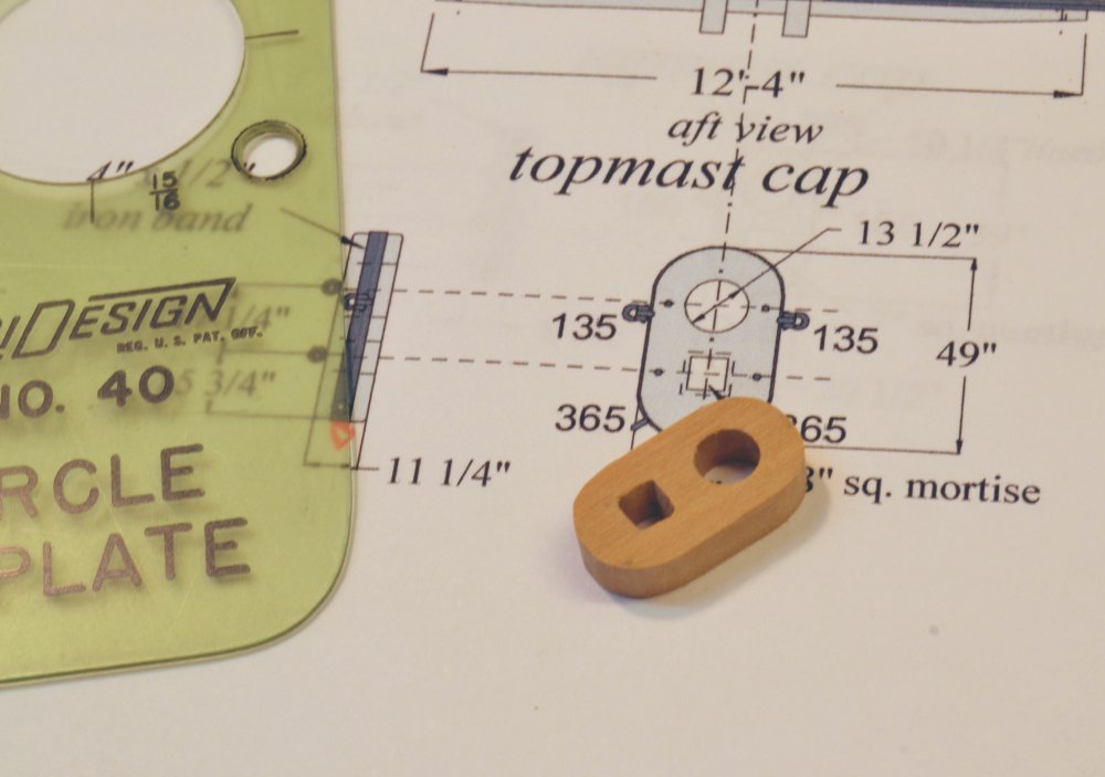
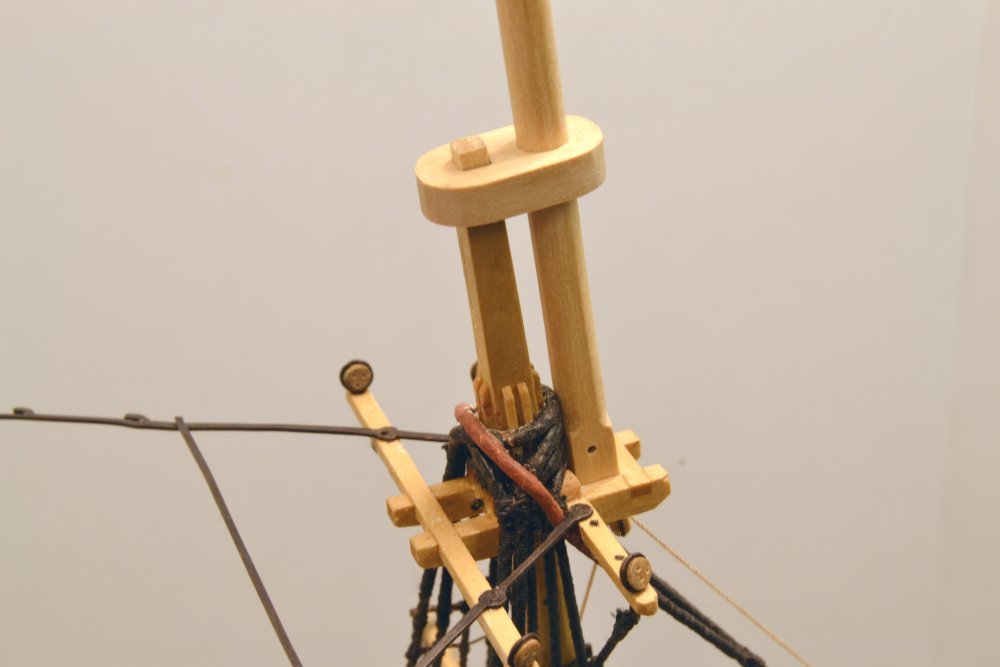
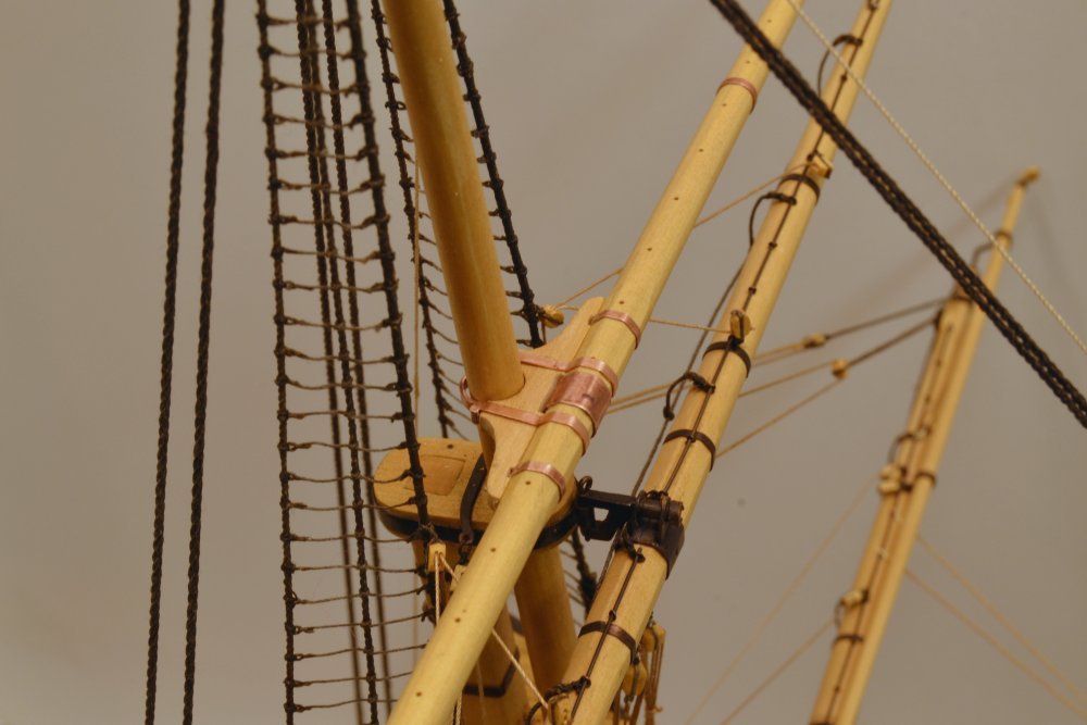
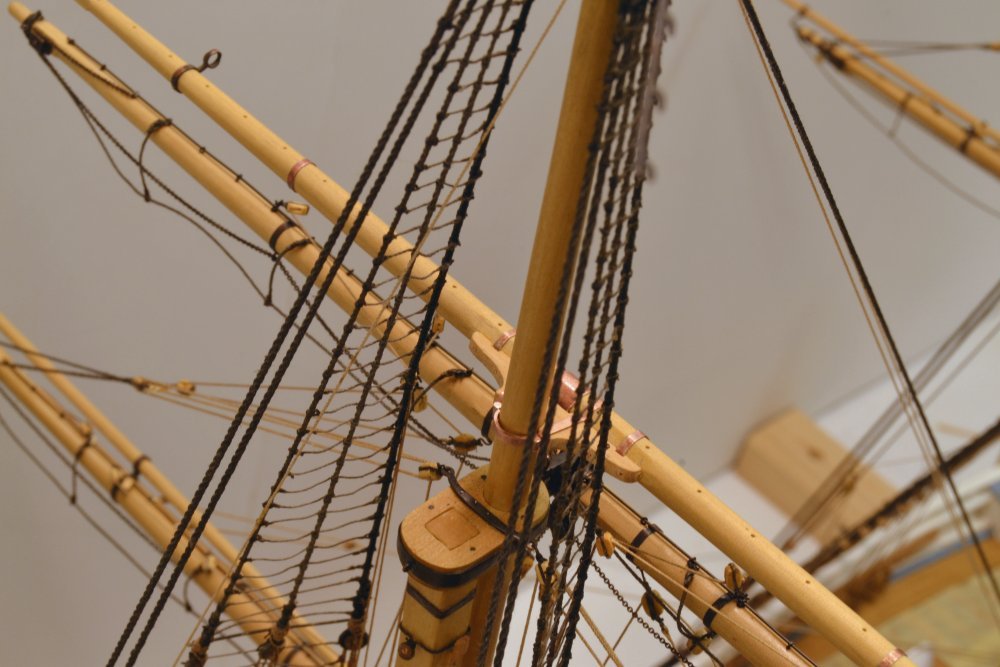
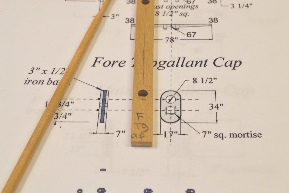
Young America - extreme clipper 1853 Part 290 – Upper Mast Caps Part 287 described making basic pieces for mast caps and parral yokes that had correctly sized holes for the upper mast sections bored on the milling machine. In the first picture one of those basic pieces has been mortised to fit its square masthead tenon – in this case on the foremast. Cutting and trimming the square mortise with a piece of this length helps to visually align the cap on the ships centerline as the square mortise is finished. The spacing between the lower and upper mast sections was also carefully marked and cut to ensure the total mast assembly was straight. In the next picture the forward end of the cap has been cut to its round shape. The circle template in the picture was used to mark the rounded ends, allowing the curves to be cut and sanded to the final shape. These curves could have been drawn with a compass before boring or mortising the holes, but this would require precise centering of the hole for boring in the rotary table and reliance on measured marking to correctly locate the square mortise in relation to the bore. Using the template to mark the non-critical shape of the ends was much easier and more efficient. The next picture shows the final cap shape. The next picture shows the main topmast cap and topgallant mast fitted temporarily. The next picture shows the fore topmast cap with its ironwork in a test fit. The topgallant mast fid mortise has been sized in this picture but the diagonal rigging sheave above the lower square has not yet been drilled and cut. The next picture shows the model with the fore and main topgallant masts temporarily fitted. The last picture shows the ironwork mounted on the main topmast cap. The ironwork on both these caps includes the reinforcing band, four eyebolts for mast rigging tackles on the underside, an aft rigging eyebolt, and side eyebolts with shackles for the upper topsail yard standing lifts. Ed
- 3,618 replies
-
- 36
-
-
- young america
- clipper
- (and 1 more)
-
Young America - extreme clipper 1853 Part 289 – Mizzen Topmast 2 I have been focusing recently on completing the remaining upper mast assemblies. Making the upper masts and boring caps to fit was described in earlier posts. There is benefit in making many of these parts together. Boring the caps and parral yokes using one milling set up was one example. Making the remaining, small crosstree assemblies will be described later. Ideally, the masts should be fitted into the crosstrees before cutting the square masthead mortises in the caps – so the masts will be straight. Installing the mizzen topmast with its crosstrees, the last of the three, will allow the topgallant masts and caps to be fitted. The first picture shows that mast, its assembled crosstrees and the parts for its iron spreader. Shaping and soldering the spreaders was described in an earlier post. The next picture shows the mast temporarily fitted. The crosstrees were glued to the mast in this position so they could be leveled in place. This levelling and side-to-side alignment was done before gluing by adjusting the angle at the hounds and the square masthead base. Final adjustment was checked and refined right after gluing. The next picture is a closer view. This picture shows the fastenings of the spreader. These are copper wire rivets through the cross tree members. An alternative to this method would be to solder in the wire bolts then glue the whole assembly into the bolt holes later – as was done with the whisker booms. This would avoid accidental bending of the assembly during rigging work. The method I used will require straightening of these before rigging the backstays that pass through the cleats. These are so vulnerable that I suspect that final straightening would be required in any case. In the next picture the ironwork has been blackened. The served futtock shrouds and deadeyes have been installed at the workbench as described in an earlier post. The picture shows the mast gripped in the vise for sizing of the masthead tenon. The mast is set in the vise with the jaws set at the base of the tenon. This allows the jaws to be used as a guide for filing all four sides of the masthead to produce the finished 8" square tenon. In the next picture the mast is set up for installing the bolsters and the eight masthead battens. The bolsters are rounded squares that prevent chafing of the shrouds. When the glue had set on the tiny battens, the tops were chamfered at an angle. The last picture shows the mizzen topmast permanently installed by gluing the lower cap to its masthead and the topmast square into the lower mast top. As with the other topmasts, gaps between the square at the base and the crosstree opening were filled with wood shim pieces. The caps for all three topmasts may now be fitted up and their square mortises marked and cut. Next time. Ed

- 3,618 replies
-
- 40
-
-
- young america
- clipper
- (and 1 more)
-
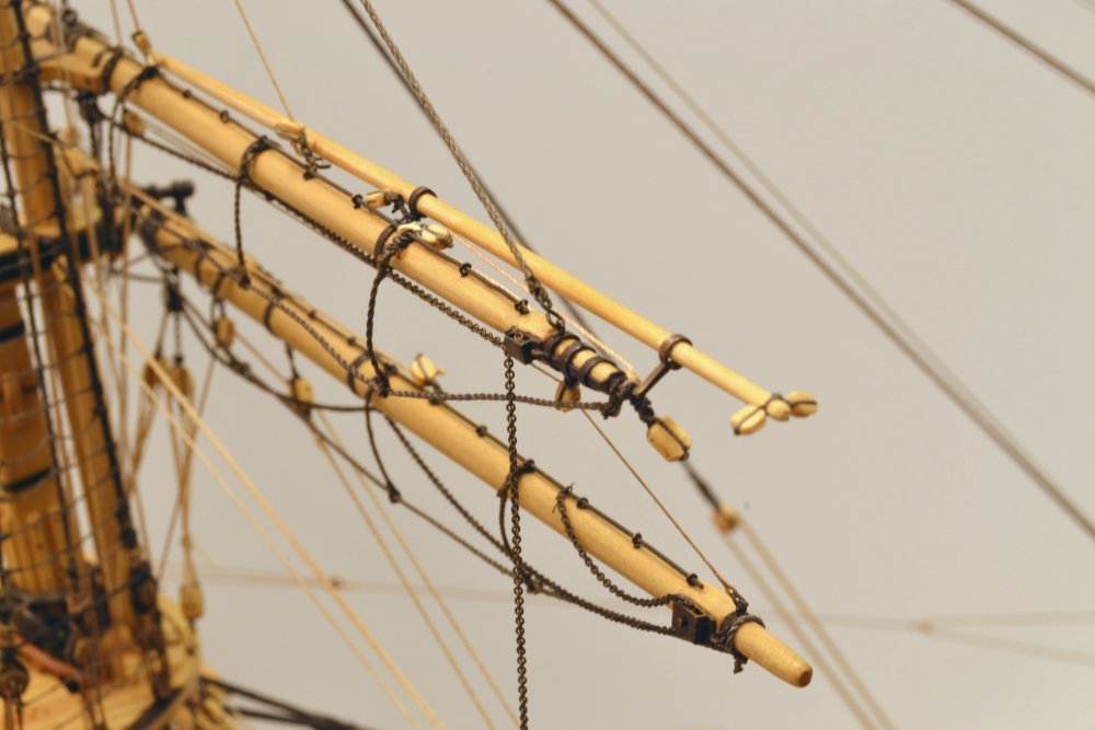
Young America - extreme clipper 1853 Part 288 –Main Topsail Yards In the first picture the main lower topsail yard has been permanently installed and rigging work is in progress. The triple tackles for the upper topsail sheets have been rigged between the sheet block and eyebolts on the main top rim. With no sails and no clew lines on the upper sail, the other ends of these chains pas through the cheek blocks and are lashed to the jackstays slightly inside the yardarm at a convenient location for shackling to the upper sail when it is bent. The length of this chain above the yard is limited to less than the working length of its tackle. The starboard lower topsail sheet and clew line has also been rigged in the picture. The next picture shows the completed rigging for this yard – except for its braces. The rigging added in this picture includes the four bunt lines and the port lower topsail sheet. The buntlines pass through double blocks lashed to the #1 top mast shrouds, then down through fairleads in the top, through fairleads on a lower shroud, to their belaying points on the main pin rails. In the next picture, the parral for the upper yard has been roughed out and is being test fit to the upper yard. After gluing and bolting to the yard, it is being test fit to the topmast in the next picture. In the next picture the hinged clasp and its strapping have been fitted and the yard again tested in position. The last picture shows the after side of the parral. The hinge and pin connections were modeled using short lengths of 18 gauge copper wire. These are fitted with pins that slide into the wood yoke. This method was described in an earlier post. The yard was then removed for further ironwork and rigging to be added. Ed
- 3,618 replies
-
- 37
-
-
- young america
- clipper
- (and 1 more)
-
ancre Chebece 1750 by Jeronimo - FINISHED
EdT replied to Jeronimo's topic in - Build logs for subjects built 1501 - 1750
Thanks for explaining, Karl. Ed -
ancre Chebece 1750 by Jeronimo - FINISHED
EdT replied to Jeronimo's topic in - Build logs for subjects built 1501 - 1750
Another masterpiece, Karl. Somehow I have allowed myself to fall behind in following your posts, but I spent some time this morning catching up. There are so many impressive features to your work. My favorites are wood finish, clean joinery, and of course the carving, to name only a few. I would love to see more of how you do this work, even if language barriers deter full explanations. Very impressive work, as usual. Ed -
Thank you, Rob, and thanks for all the other comments and likes. Yes, the masts and yards are a lot of work - even before getting to the rigging. A lot of pieces and a lot of ironwork. Ed
- 3,618 replies
-
- 4
-
-
- young america
- clipper
- (and 1 more)
-
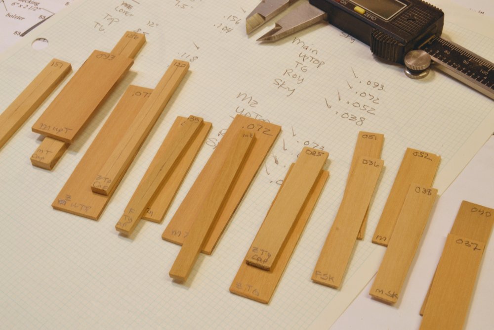
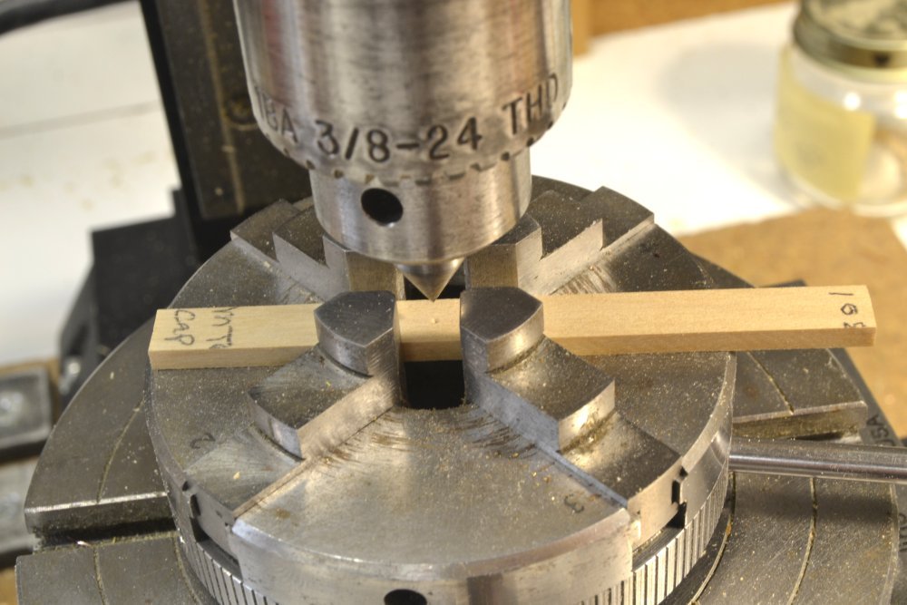
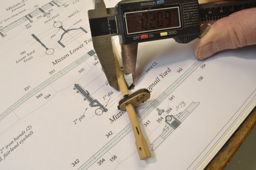
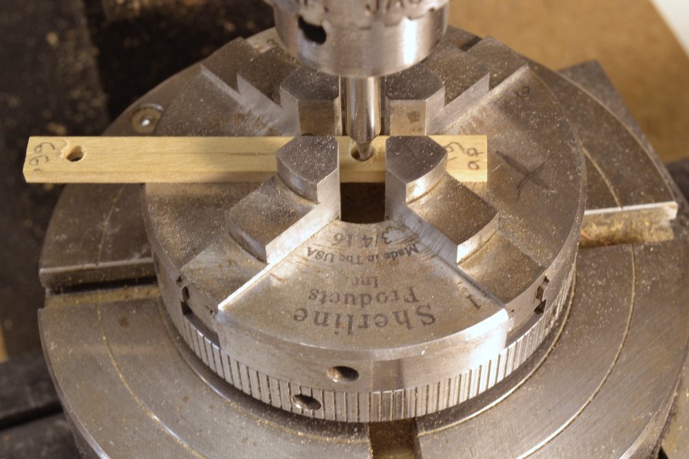
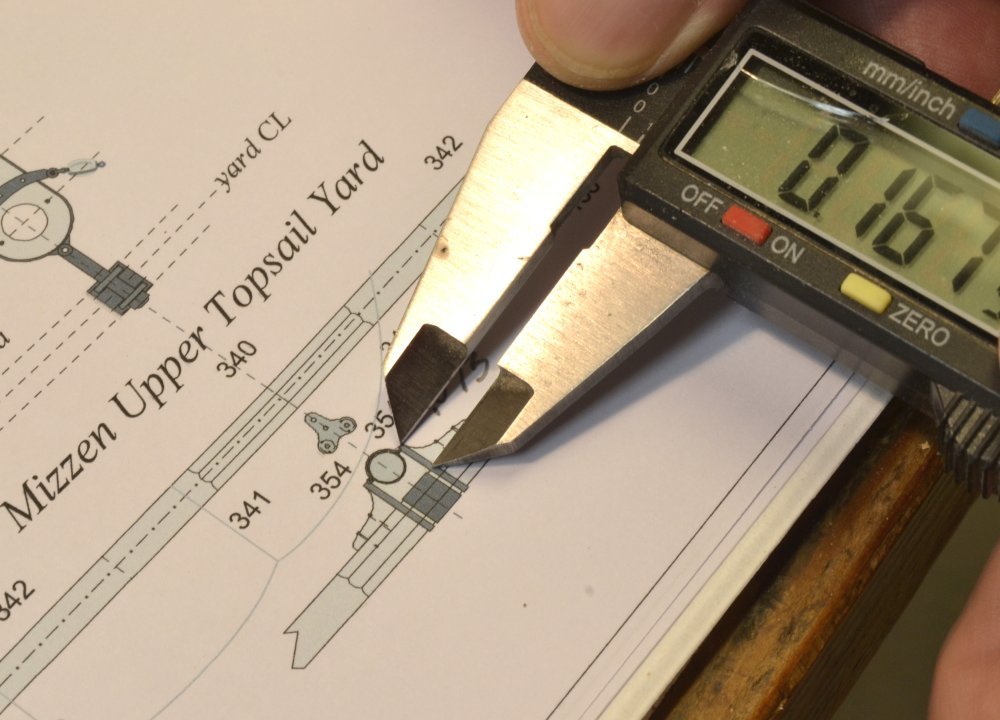
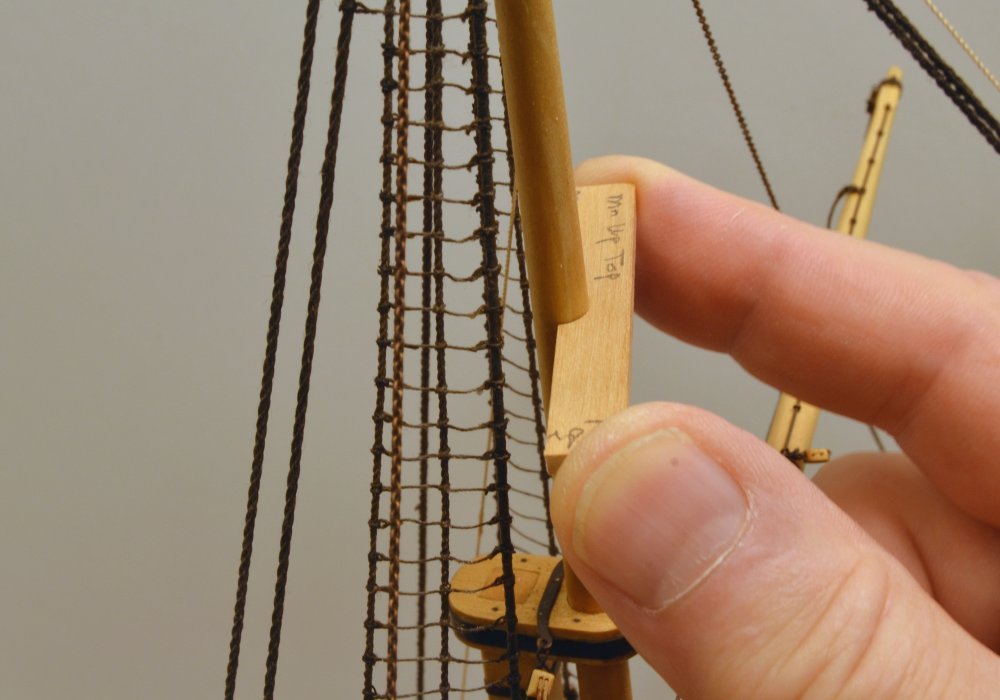
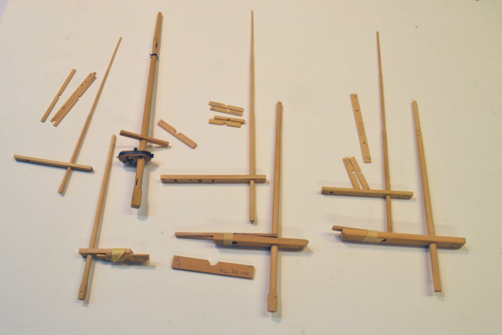
Young America - extreme clipper 1853 Part 287 –Mast Caps and Parral Yokes As was mentioned in the last post, making all the upper masts allowed the bores for both the caps and parral yokes to be made and fitted efficiently using one basic milling machine set up. Holes were bored using the rotary table with the milling bit offset to produce each required bore diameter to fit its appropriate mast. The first step was to create the necessary blanks of proper thickness for each required piece. The first picture shows the collection of blanks for all the remaining caps and parrals. To make these efficiently, a list of thicknesses was tabulated from the drawings. Long (12") wood blanks were then reduced to size on the thickness sender starting with the thickest, then cutting off a roughly 3" blank, then reducing the thickness, cutting off the next blank, and so on. The next step on each of these was to cut it to the required width. The next picture shows a correct-width blank for a cap with its center being marked using a center point in the mill chuck that has been precisely centered on the rotary table. This mark – on the center of the bore - permitted a center line to be drawn on the piece that will later be used to mark out the shape of the cap and the square mortise for the masthead tenon. This line was only needed on cap pieces. The four-jaw centering chuck is a convenient way to hold these pieces, but a check should be made to determine which pair of jaws centers the work most precisely. The next picture shows a centerline being drawn with a compass. To set the bore, the actual mast diameter was used, although this differed from the drawing diameter by at most a few thousandths of an inch. I did not leave an allowance for a simulated leather lining on either the caps or the parrals, but this could be done by increasing the offset by the thickness of the expected lining. The milling bit diameter – smaller than the final bore - was subtracted from the mast diameter measurement and the remainder divided by 2 to determine the radial offset of the bit. The table is rotated to make the hole. The next picture shows the offset bit boring a hole in a cap piece. These blanks were made long enough to produce at least two final pieces as insurance against later finishing errors. Also, each setup was checked for fit after initial boring – usually on a scrap piece – so any necessary offset adjustments could be made before making the final bores. The next picture shows a cap piece after boring and fitting to the mast. This piece will later be marked out for final length, shape, and cutting of the square mortise. After boring each cap hole, the same mill setup and offset was used to bore the parral yoke for the yard above. Each parral blank was first ripped to double width based on measurements taken from the drawings as shown in the next picture. The calipers were used to measure the parral width, which was then doubled to set the blank width for boring. This method is accurate enough for the purpose. After boring, the piece was ripped to the width measured above leaving a half-circle. No centerlines were not needed on the parral pieces. The next picture shows the main upper topsail parral piece being checked on the mast. The parrals will be cut to length and shaped later when the yards are made. The last picture shows all the basic bored pieces – masts, caps and parrals - with some duplicates, ready for the next steps. The mizzen topmast was included here since it has not yet been permanently installed. This process worked well and saved a lot of machine setup time vs. making these parts one at a time as needed, although re-centering of the milling chuck was required a few times. With the smaller bores, offsets were adjusted based on the previous bore then checked by trial and error, rather than returning to center each time. Scrap pieces were used for trial and error fitting of the bored holes. It took about four hours to make all these cap and parral pieces – pre-work thinking time not included. Ed
- 3,618 replies
-
- 44
-
-
- young america
- clipper
- (and 1 more)