EdT
-
Posts
2,214 -
Joined
-
Last visited
Content Type
Profiles
Forums
Gallery
Events
Everything posted by EdT
-
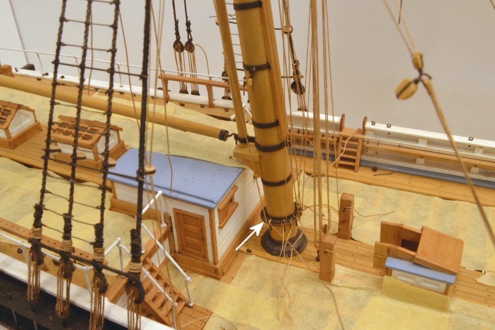
Robert Bennett Forbes of Boston began fitting double topsails in 1844. His design featured an extended masthead with a collar on the topmast below the cap to support the yard. By 1853 people began fitting what became the Howes type truss to a boss on the lower masthead cap to support an upper topsail. These were generally fitted to the standard masthead, sometimes with a strut from a collar on the topmast below the cap. Using the existing, standard masthead made the conversion easier. Frederick Howes of Yarmouth, Mass. patented this rig in 1854. This basic type of truss was fitted to YA's 3 masts about a year after launch in 1854 and is the type fitted to my model. Perhaps these were adopted later in Europe as you suggest. Ed
- 3,618 replies
-
- 1
-

-
- young america
- clipper
- (and 1 more)
-
To answer your questions, Rob, there will be Spencer gaffs on the fore and main and a monkey (pennant) gaff on the mizzen, all per the original Webb sail plan. I am modeling the ship roughly as configured after the addition of double topsails in 1854, one year after launch, and before the conversion to single-stick topgallant/royal/skysail pole masts at an unknown later date, but before the two photos taken in the 1870's. So, I believe the period would be mid to late 1850's. I should add that this would be during her "extreme" period. Ed
- 3,618 replies
-
- 1
-
-
- young america
- clipper
- (and 1 more)
-
Spectacular precise joinery, Micheal. Bravo. Seeing your hands in the photo makes me envious of your scale. Ed
-
Lovely clean framing, Montanes. Ed
-
Congratulations on the completion of a fine model, Nils. Love the people. What's next? Ed
- 692 replies
-
- 2
-
-
- eagle of algier
- chebec
- (and 2 more)
-
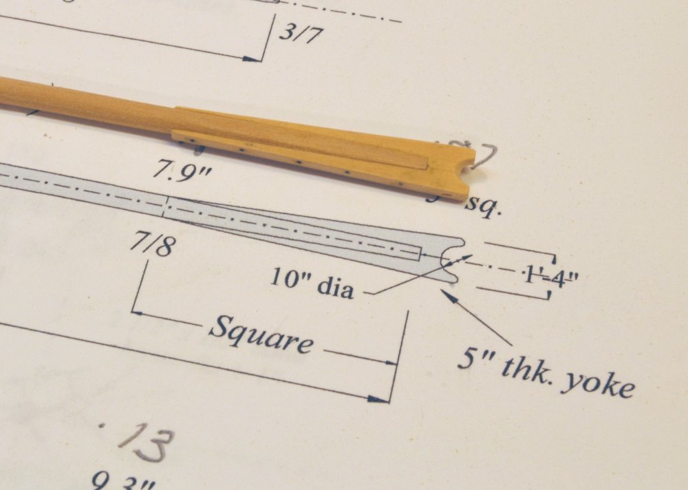
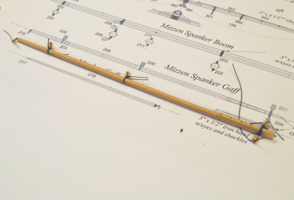
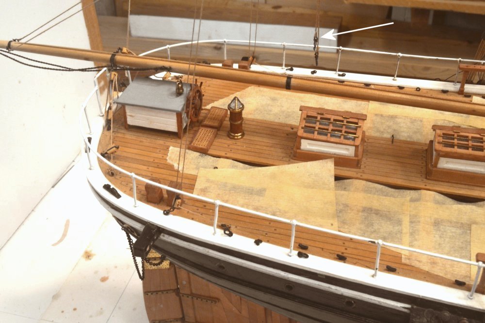
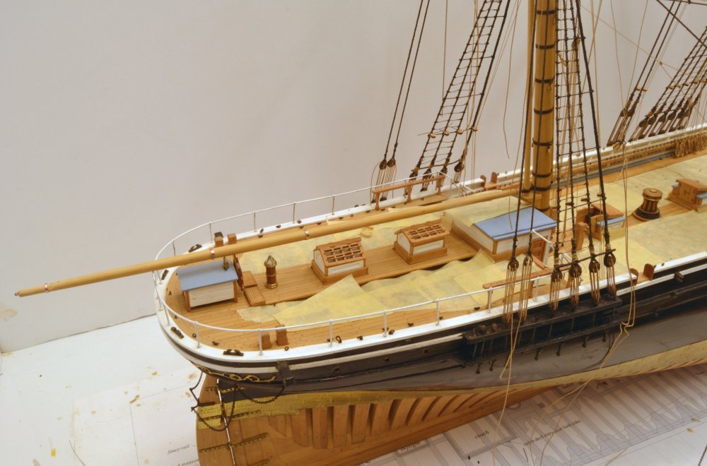
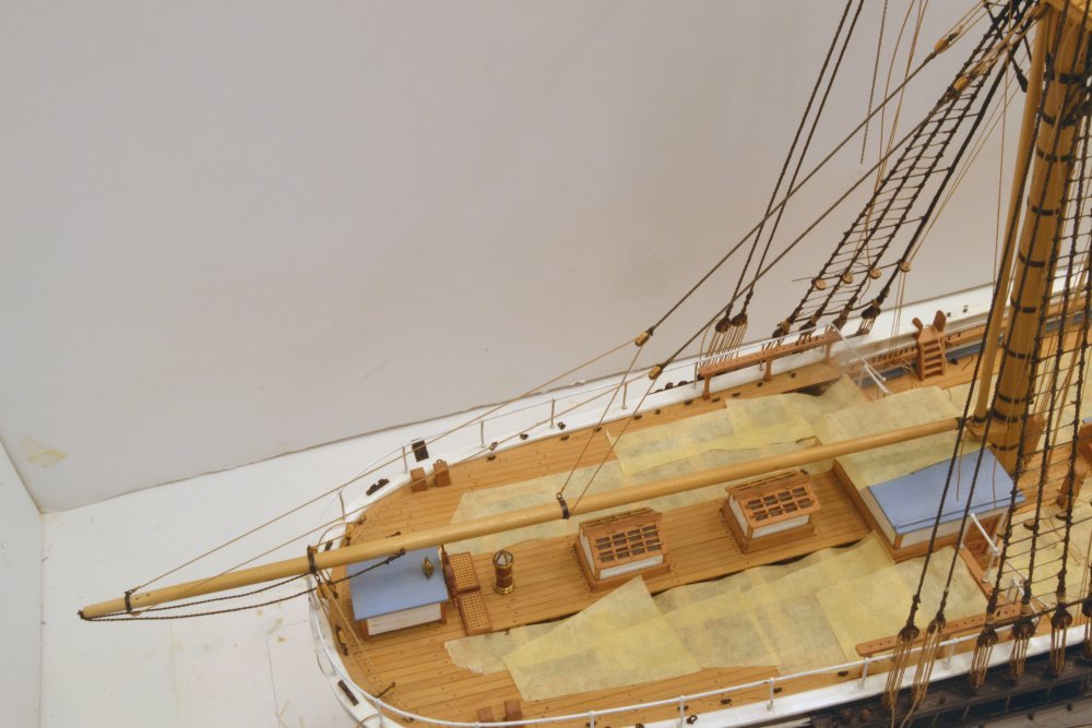
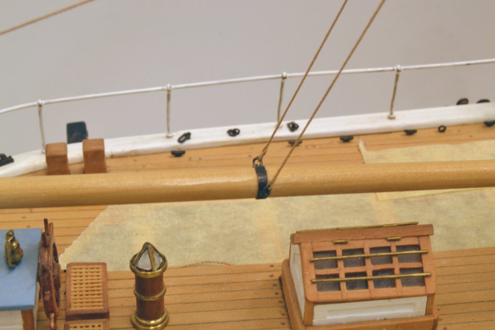
Young America - extreme clipper 1853 Part 304 – Spanker Boom 2/Gaff 1 Done with rework, back to moving the ball forward - hopefully. This post describes completion of the boom rigging. Gaff rigging seen in these pictures will be covered in a later post. The first picture shows the corrected topping lift spans as well as cosmetic repair to the boom at the old band position. The foot ropes and the boom sheets are also shown in this picture. The three lines running vertically to the gaff in this picture will be described later. The boom sheets are luff tackles with lead blocks, one on each side of the boom just aft of the wheel enclosure. Each consists of a double block shackled to the boom band, a single block hooked to a deck eyebolt, a second lead block also hooked to a deck eye, and finally a cleat in the deck to belay the fall. The next picture may show this more clearly. The sheets control the sweep of the boom. The boom is also fitted with an inhauler and outhauler that attach to the clew of the spanker sail. In the absence of sails, the outhauler is stopped at the gooseneck, runs aft over the boom to a sheave near the end, back under the boom to a cleat near the foot, with the remaining line coiled on the roof of the cabin. The line and boom sheave may be seen in the above photo and the inner end in the next. The inhauler is a very short line on the no-sails model. It is stopped at the end in a block strapped to the gooseneck and belayed just below on the spider band, where most of this line will be coiled on the model. This line would also be secured to the clew and run out by the outhauler when setting the sail. The next few pictures show fabrication of the gaff. In the first, the spar has been shaped by the usual methods. The 40' spar is 9" at its maximum diameter, which occurs 1/3 in from the outer end, as on the boom. Five inch thick wood blanks have been cut to form the jaws of the yoke that will secure the gaff to the spanker mast. The jaws were first glued and clamped to the sides of the gaff, then shaped. Cross bolts were then added using black monofilament. In the last picture an iron band around the jaws has been fitted and the necessary blocks have been lashed to the spar and to eyebolts in the band. After the addition of lashing eyes on the jaws and clipping of the excess block lashings, the gaff will be ready to go up. Ed
- 3,618 replies
-
- 22
-
-
- young america
- clipper
- (and 1 more)
-
Bob, I really wanted to get off of this. You said: My copy of Crothers' book has the forward end of the span fastened ahead of where the vector line of the pendant crosses the boom, of that I am sure. No matter, though. With the span running through a block on the pendant, the vector of the pendant will always fall between the two legs of the span regardless of where the ends of the span are fixed. Ed
- 3,618 replies
-
- 1
-
-
- young america
- clipper
- (and 1 more)
-
Bob, all this is not making me crazy - but I confess to getting weary. At the same time I rejoice that the other 700 or so lines on the model are not getting this kind of oversight. I am comfortably going to stick with my current configuration. I am tempted to take issue with a number of points in your latest post where I disagree, but in the interest of time will instead focus on your final point, one item that I believe we agree on: The location of my span shackles are almost precisely proportional to Crothers' representative drawing in his first book, which you "entirely agree with" as well as his model drawings. Ed
- 3,618 replies
-
- 5
-
-
- young america
- clipper
- (and 1 more)
-
A good method Druxey. The three that I have done on the model so far were done in place in some fairly inaccessible locations and/or among other lines. The method I used was to pass a needle with the one rope end through the other rope at an angle, soak the joint with Titebond glue, roll it between fingers and wait until completely dry, then clip off the excess ends. The lines were Nos. 60 and 40 DMC cotton. I use the same method on DMC 80 ratline eyesplices. You are right, the pva glue holds well - if you wait for it to completely dry.
- 3,618 replies
-
- 3
-
-
- young america
- clipper
- (and 1 more)
-
Bob, please do not apologize for making comments or suggestions. That is the purpose of the forum. Most of the comments I receive are constructive and helpful. I welcome them, though I may not always agree or adopt. There was no confusion in my mind with your suggestion. It was very clear. I am aware that my correction differs. I will try to explain that and then offer some comments on my general research/design process. When I noticed the shortness of the tackles, before your comments, I went back to my sources and found that I had incorrectly placed the forward lift band. My design for the topping lifts is based on the William Crothers drawing for Young America. This drawing is my backup when primary sources are not sufficiently definitive. I believe that his design for the lift - and many other things - was based on meticulous examination of the photographs of the ship as well as other primary sources. So I went back to the photos to determine if there was a basis for his boom lift design. There was. These photos, taken in the 1870's show a shorter boom than the original sail plan, but the forward lift band is clearly visible, as are the lift tackles. Proportionally, the forward band is well aft and the tackles angle toward a midpoint consistent with the placement of the lift bands on the Crothers drawing - and now on my drawing as well. So, your comments and the Niagara replica pictures notwithstanding, I am comfortable with my current configuration. Because my interpretations of many design aspects will be cast into the concrete of my books, I need to be careful about having documented sources wherever possible. I owe this to the readers. While I cannot claim exhaustive research, the order for this is: primary YA documents first, then primary general documents, then secondary sources in order of their credibility, then finally my judgement as a last necessary resort when there are conflicts or unknowns. All the applied sources are listed in bibliographies. There is no single or perfect interpretation of history, especially of the minutiae we are dealing with. We do the best we can. Thanks for your input - truly. Ed
- 3,618 replies
-
- 4
-
-
- young america
- clipper
- (and 1 more)
-
Fantastic, Micheal. I have been going back over your early posts. The metalwork knocks me out. Ed
-
Difficult to explain the glue swelling, Paul. Titebond II is a waterproof glue. I paint acrlic over it all the time. Could it be the sanding sealer? Curious problem. Ed
-
Thank you for the pics, Dowmer - nice to see. I have filled the old holes with a glue/sanding dust mix and have painted them over with some color matched acrylic that I hope will obscure the fix. If it does I will swab the area with the wipe-on poly I am using on all spars. We'll see. Ed
- 3,618 replies
-
- 3
-
-
- young america
- clipper
- (and 1 more)
-
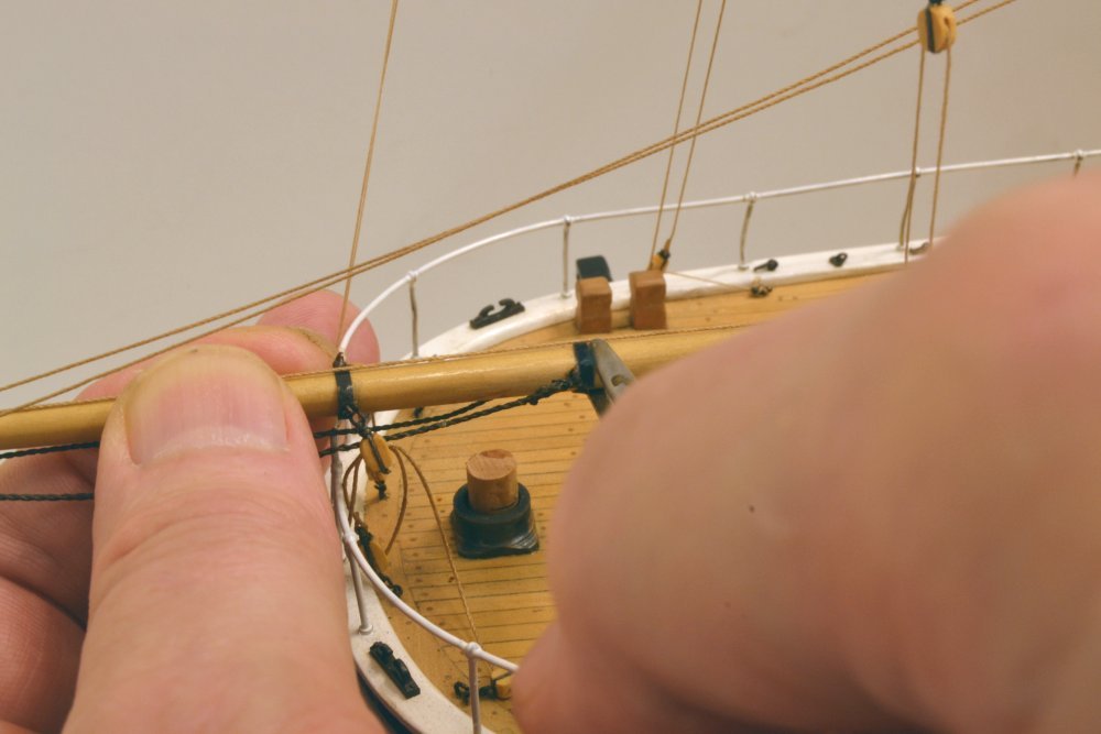
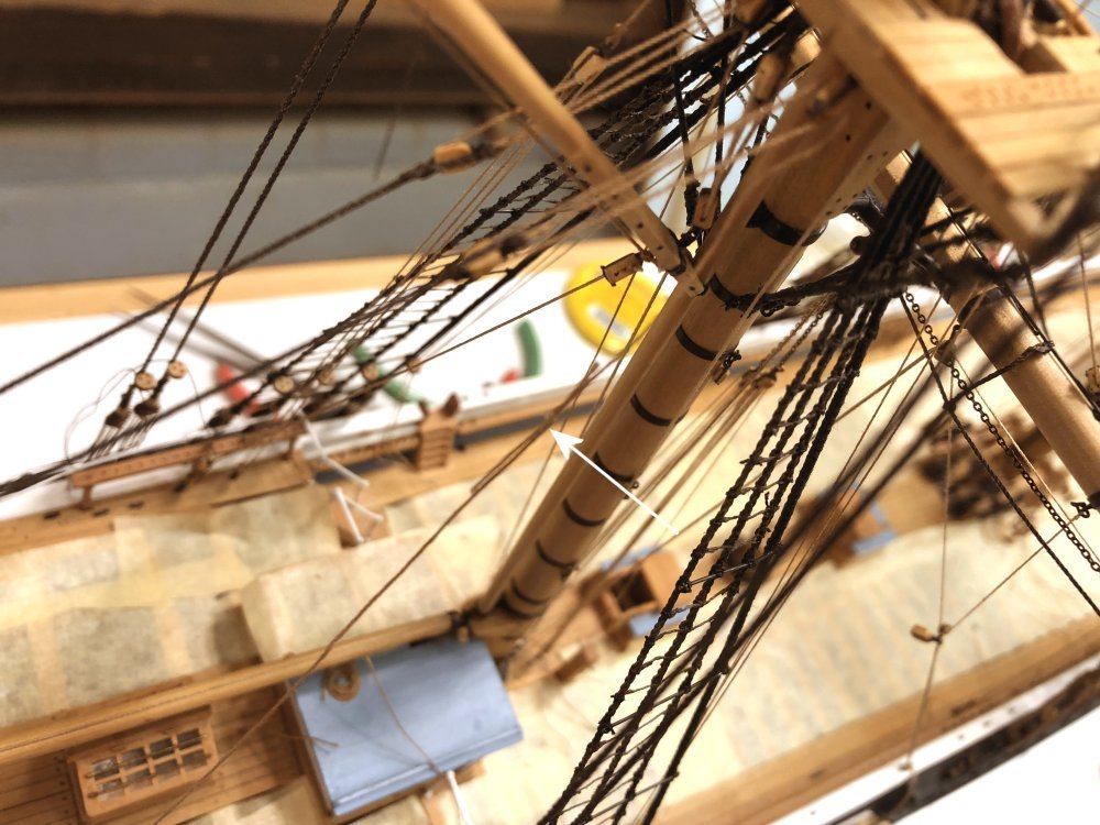
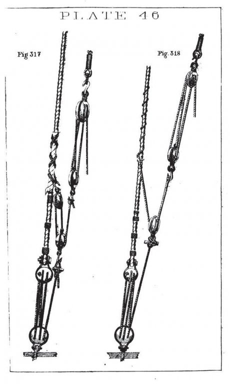
Young America - extreme clipper 1853 Part 303 – Boom Topping Lifts Revisited Let me politely try again. Please start a new topic. Meanwhile, back to the business of this model. The first installation of the spanker boom topping lifts was not correct. I was not completely satisfied and others noticed the problem. I wanted to fix it, but the question was how to do that without dismantling more than two day's work. First, some discussion of these lines is appropriate. The purpose of the topping lifts was to hold up the outer end of the spanker boom when the sail was furled or for reefing. The sail itself supported the boom at other times when set. During reefing, the gaff was lowered to allow the sail to be shortened by tying off reef points to the boom, so the boom needed support. The amount of lift required at the end of the boom was probably in the range of 5 to 10 feet – not a lot. Different configurations were used. A single lift from the end of the boom through a sheave at the end of the gaff to a block at the top was often used. Single pendants on either side of the boom were also common. To distribute the lifting force over more of the boom-end, a doubled span through a single pendant block was also used. There may have been other arrangements. Lacking any specific YA design data, I chose the third option based on the large size of the boom and relying - as I often did in matters like this – on Bill Crothers' drawings. He showed this arrangement for both Young America and Lightning and showed two single pendants on his Challenge drawing. With the length of the doubled span and of the pendant specified at 48' and 24' respectively, the lengths of the tackles would be correct – if the forward span connection was correctly located on the spar. It was not – a drawing mistake by me. The first picture, of the original installation, shows the movement of the band and shackles required to correct the error. To make this correction and to avoid dismantling the entire spar, I decided to try and do it in place. In the next picture the two shackles have been pulled out of the band with pliers and are hanging just above the spar. Sliding the tightly fitted band along the spar was the most risky and difficult part of the job. It was done mostly by pushing with pliers while firmly holding the end of the spar as shown in the next picture. In the picture the final position has been reached with the only damage being the (usual) bending of the iron railing. The wheel enclosure and binnacle were removed for their safety. New holes for the shackles were then drilled into the spar through the existing band holes. In the next picture the starboard span shackle has been fitted and re-glued into the relocated band. And in the next, both spans have been re-rigged. To allow relocation of these connections, the belaying points had to be cast loose and the tackles lengthened. The next picture shows the two topping lifts with the falls pulled down. The length between the two tackle blocks has been increased from about 54" to about 86" – a satisfactory correction. The fall on the port side had just enough length to permit re-belaying on the spider band. The starboard fall was left short, however. Rather than re-rig the tackle, a splice was put into the line as shown in the next picture. When the glue holding this splice together has dried, the excess ends will be clipped and if the appearance is OK, the line will be belayed. If not it may be replaced or redone. There are two such splices in other parts of the rigging so far – perhaps no one has noticed. Some cosmetic repair to the spar itself will complete the job. I hate rework, but my nature seems to generate it on occasion. And, oh yes, the drawings will of course be corrected. Other boom/gaff rigging shown in the above pictures will be described in a later post. Ed
- 3,618 replies
-
- 27
-
-
- young america
- clipper
- (and 1 more)
-
Well, my instincts about raising this opinion-charged topic appear to have been correct, so if there is still energy to debate this, please someone start a new topic. I suggest we move on. Ed ps. Thank you, Danny.
- 3,618 replies
-
- 4
-
-
- young america
- clipper
- (and 1 more)
-
Did you start this, Dowmer? Oh, my. Also, I'd like to put in a vote for not quoting entire posts - takes up space and makes it harder to follow a conversation. We are already at 106 pages. I'm glad to see we are on the same page with dark brown, Druxey - maybe or maybe not exactly the same shade, but......not black. Ed
- 3,618 replies
-
- 3
-
-
- young america
- clipper
- (and 1 more)
-
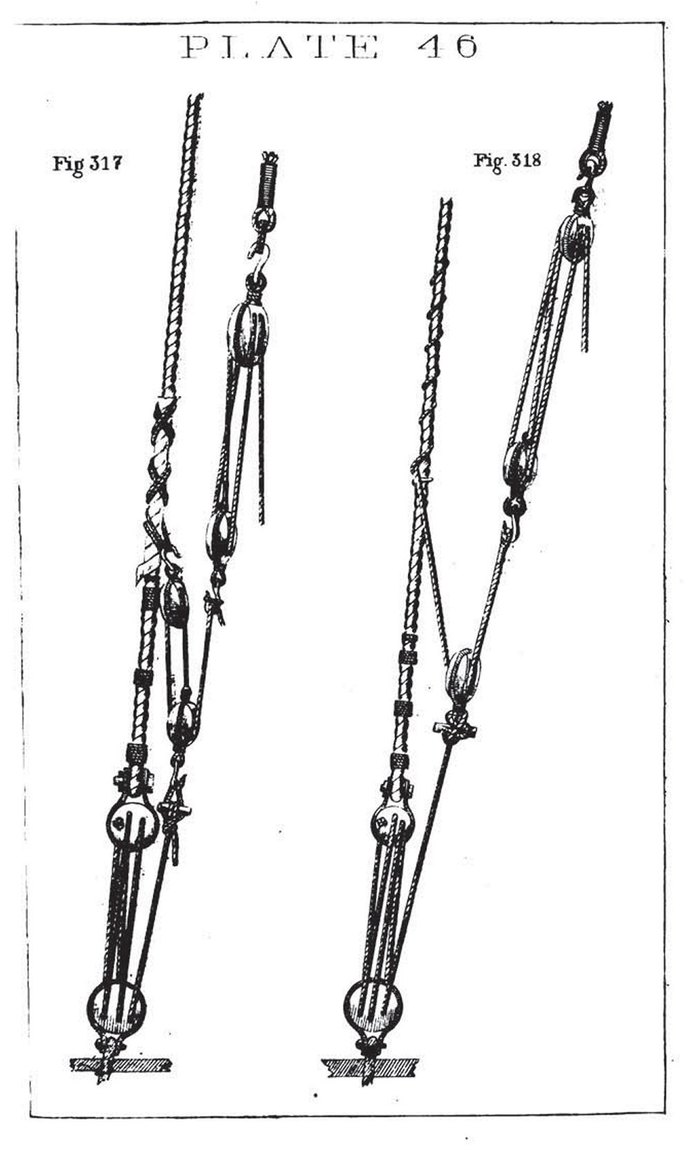
All these great comments. I can hardly keep up, but let me try. Bob Cleek raised a number of good points worthy of comment. At 1600 sq ft, the spanker was Young America's 7th largest sail on the original single topsail rig, with the main and fore topsails being the largest at 2840 and 2600 sqft respectively, followed by the courses. With double topsails it ranks 3rd or 4th in size depending on the crojack size which is not specified on the original sail plan. It was still a lot of canvas. I do not know the method or methods used to take in this sail, but I installed brail blocks on the mizzen mast as well as the other lines shown or those that will be shown in succeeding posts. Color of lanyards is a subject that I hesitate to engage in because it is one of those hot buttons that invite many strongly held opinions. I would suggest that someone – not me – create a topic on this subject. I will gladly participate there with my admittedly limited knowledge. I will, however, at the risk of inviting more comments on this build log, contribute here what I believe are some facts: 1. Deadeyes and lanyards were used not only on shrouds but also on backstays. 2. On a 3-4 month voyage around Cape Horn, upper masts would be struck down, probably more than once, requiring re-rigging of their stays and shrouds at sea. 3. Climate variations between say a New York summer at the start of a voyage, equatorial conditions a month later, and semi-arctic conditions at the Cape a month after that, followed by a repeat of those variations up the Pacific, as well as the case described by wefalck, would certainly alter the tension in the standing rigging essential to the support of masts. 4. All hemp strands were tarred as part of the rope-making process – hence the straw-color (see Luce, Seamanship 1868). No doubt the effects of sun, salt and weather would lighten this over time. 5. The treatment applied to standing rigging discussed in earlier posts, according to primary documentation widely used at the time (again Luce, 1868), can only be described as thick, black, tarry paint. – black due to the carbon black content, thick due to the addition of letharge (lead oxide), tarry due to the pine tar. 6. The relatively complex lanyard/deadeye apparatus is obviously designed to add mechanical advantage (6 to 1) to force applied to the lanyard. It was clearly intended for applying tension as the following well known diagram shows. 7. Methods and practices have evolved over time. Even early 20th century practices were different than those of the 1860's - and wire was different from hemp. So, if I accept the above as facts, I ask the following questions: 1. Why install a large number of contraptions like deadeye/lanyards if they would rarely if ever be used? Why not just seize shrouds/backstays to chains after initial tightening? 2. If these were needed to re-tension or re-rig backstays or even shrouds, why would one clog up this friction-prone device with a thick, tarry paint? 3. If greasing rigging with galley slush or other lubricant was common at the time, why would this not be used on deadeye lanyards, at least when needed? 4. What does all this mean to the color of model lanyards? I am sure others will approach this issue differently, but this has been my rationale and my reasons for dark, but not black, lanyards. Rob, I believe Hervey Garret Smith's comments on deadeyes apply to 20th century yachts, and his description of tar is different than the tar coating described in Luce for application to the "standing" parts of standing rigging. What he describes as a "thin liquid pine oil" would not be black. As for the boom topping lift configuration that Bob very observantly mentioned, I also noted the shortness of the upper tackles after rigging them. I am addressing this question, considering correction, and will comment in a later post. Thanks for highlighting this, Bob. Cheers, everyone. Ed
- 3,618 replies
-
- 15
-
-
- young america
- clipper
- (and 1 more)
-
Thank you Druxey. Your comments and input are always well appreciated - and thanks to all who have commented or reacted to the last post. Wefalck, I cannot say how the spanker was taken in, but it was certainly equipped with the gear to lower the gaff - at least it will be on my model - as will be seen in the upcoming posts on rigging the gaff. I suspect it was able to be furled with the gaff up, since the mast is fitted with brail blocks, which I believe were used for that purpose - plus boom and gaff inhaulers and outhaulers. Others may have more knowledgeable input on this. Dowmer, I personally do not believe that lanyards were tarred because this would make them very hard to adjust to tension the shrouds and backstays. I rather suspect that they were greased, which would also give them a dark color. I intended mine to be a darker walnut and I may treat them further, but I have been reserving black for tarred lines. I also owe you a response from a previous question about Londonderry linen thread for ropemaking. I acquired a spool of 100/3 to test. I do not find it satisfactory for rope-making or for line as-is. I found roughly one slub every 6inches of thread, whereas in the Barbour 100/3 a slub occurs at about every 6 feet on average and many are very small. The Londonderry thread is also less tightly wound and very fuzzy. So, for me it would be a no go. Ed
- 3,618 replies
-
- 1
-
-
- young america
- clipper
- (and 1 more)
-
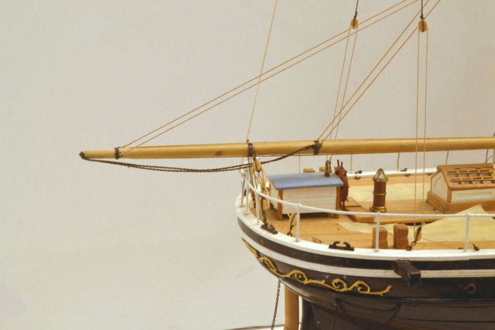
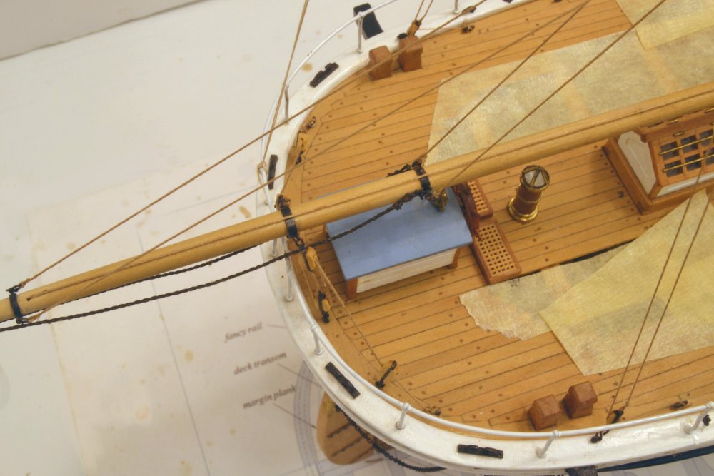
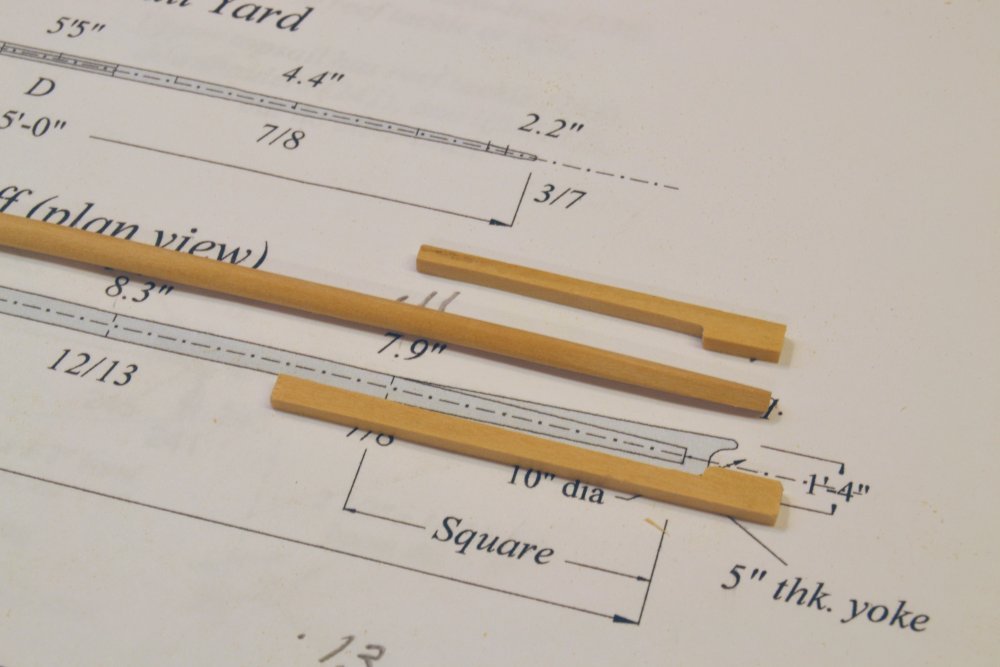
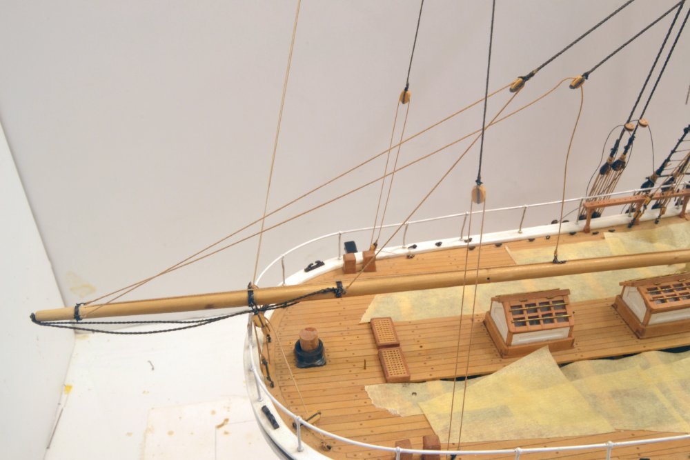
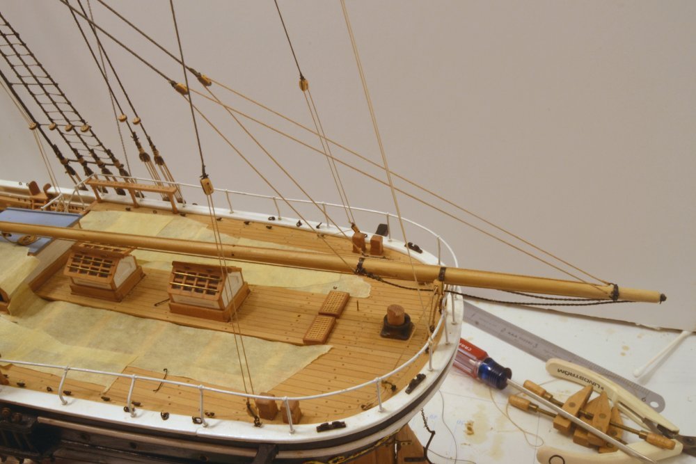
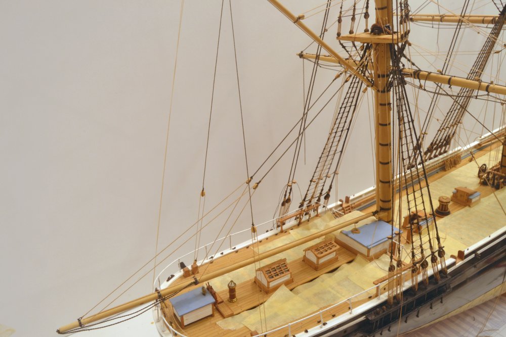
Young America - extreme clipper 1853 Part 302 – Spanker Boom 1 This is a slight diversion from the fore topgallant yard left unfinished in the last post. I will return to that shortly. The work described below was concurrent with that. The spanker boom is a large spar – 62' long and 14" maximum diameter. It is anchored to the lower end of the spanker mast with an iron gooseneck inserted in a fitting that was described in an earlier post. The first picture shows the boom temporarily set up in position. Some of the copper ironwork has been fitted in this picture. Unfortunately, the band over the wheelhouse had to be moved aft. In this position the boom sheets that attach to it would foul the wheel house as will be seen later. After the correction – including the drawing correction - the hardware on the boom was completed and blackened, as may be seen in the next picture. The boom sheets and footropes seen in this picture will be described in a later post. The first lines to be installed were the two boom topping lifts shown in the picture. Each of these consists of a 5" central pendant with 10" blocks spliced on at each end. The lower blocks are reeved with a 3" span that is shackled to the boom at each end. The span allows the boom to be supported equally at two points regardless of angle. The shackled connections at the center of the boom are shown in the next picture. Shackles allow the connections of the spans to be spliced eyes with thimbles (no thimbles at this size) and still be disconnected from the eyebolt on the spar. The next picture shows the two pendants A lot of loose ends visible in this picture and many not shown – soon to be tidied up. The next picture shows a close up of the luff tackles at the top of the lifts. These consist of single blocks on the pendants and double blocks hooked under the top. The 3" falls are belayed below on the spider band as seen in the next picture. Again, a lot of loose ends that will soon be clipped off when all the line tensions are right. The spider band is about half full at this point. More rigging of the boom in the next post. Ed
- 3,618 replies
-
- 34
-
-
- young america
- clipper
- (and 1 more)
-
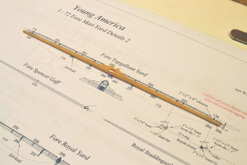
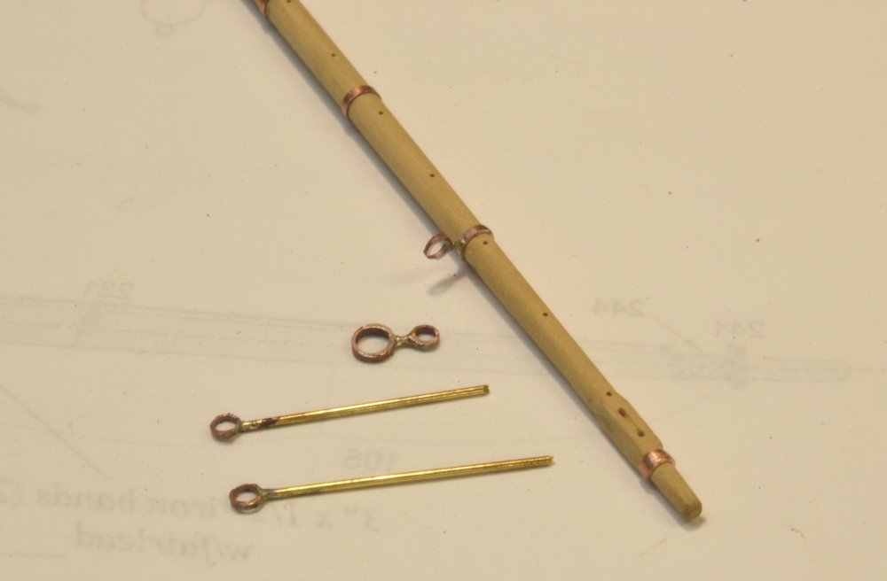
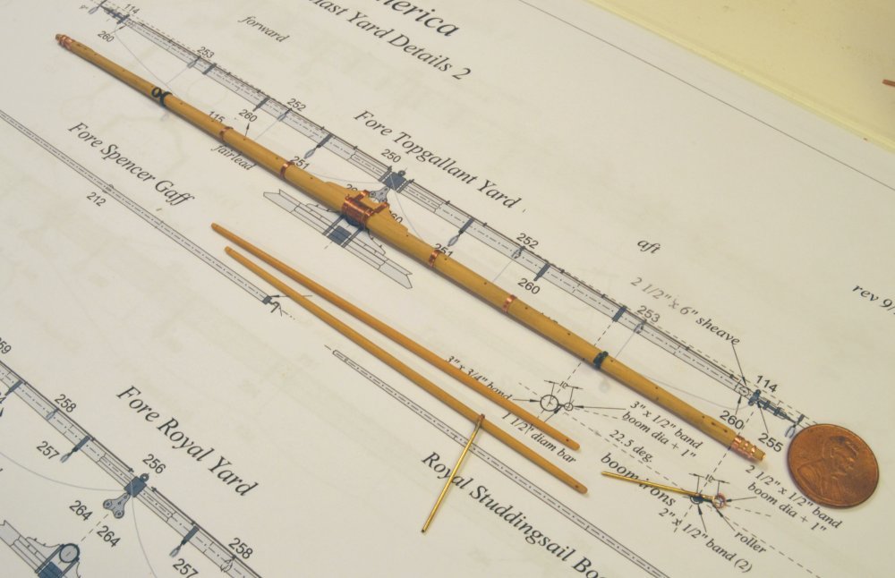
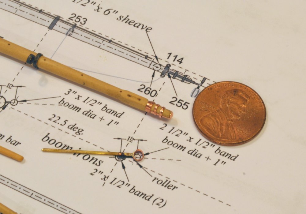
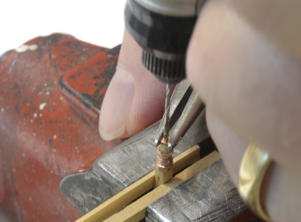
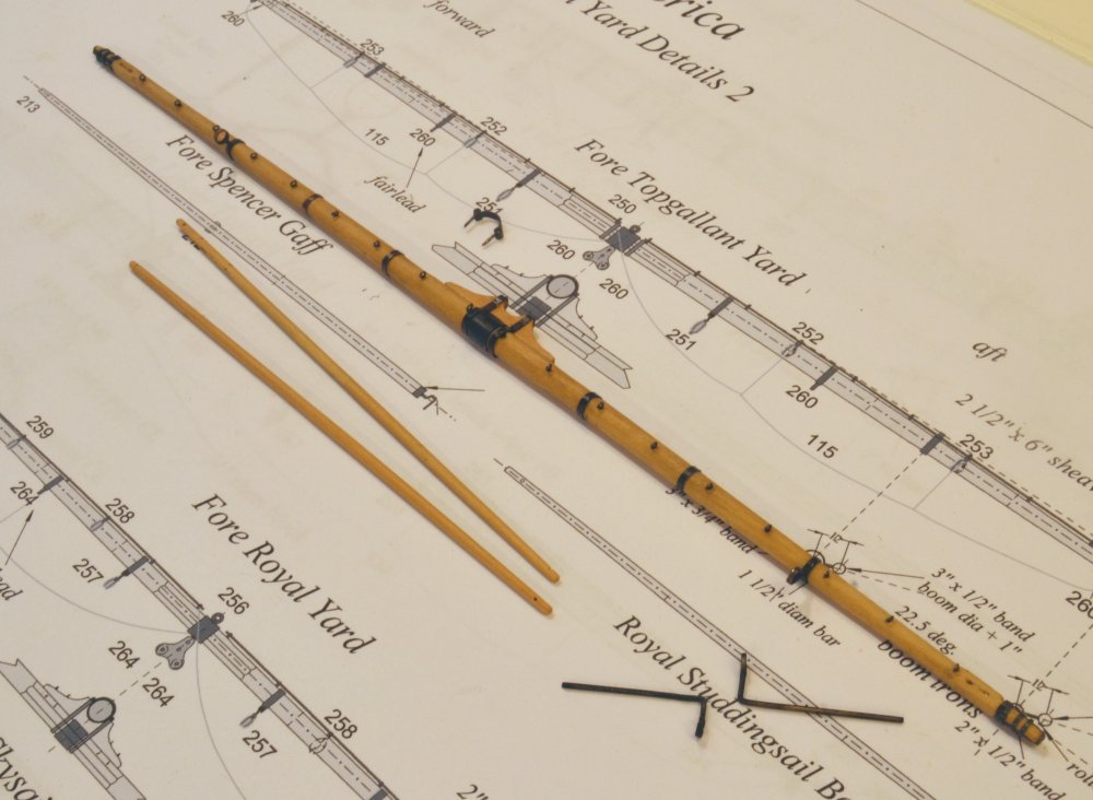
Young America - extreme clipper 1853 Part 301 – Fore Topgallant Yard 1 Since I have made a number of posts on yards and their rigging, I will try not to be too repetitive in describing those that remain. The first picture shows the fore topgallant yard after attaching the parral yoke over the central sling band. The yard was made as described earlier. One exception for this and other smaller yards is that the yardarms have through sheaves rather than the iron cheek blocks fitted on the larger yards. These were drilled, along with the jackstay stanchion holes, before any tapering of the spar. The sheave is merely carved into the wood as was done on the upper mast sheaves. In the next picture the iron (copper) bands have been fitted and the studding sail gear fabricated. The inner bands are soldered strips. The yardarm band is an expanded bit of copper tube. Brass was used on the outer boom irons because it is stiffer than copper. The next picture shows the yard with the inner boom irons fitted. These are blackened with Brass Black, so unlike the copper they had to be blackened before fitting. The picture also shows the booms as well as the reinforcing ironwork over the yardarm. The next picture shows a closer view of this. The outer boom irons will need to be bent and cut to length before insertion into the ends of the yard. The next picture shows how holes for these were drilled. After securing the end strap with two fitted rings, the enlarged end of the strap was center-marked and drill as shown, with pliers holding the sides of the strap to prevent it from spinning and destroying itself. The square section inside the yardarm was held in the vise with wood battens. The last picture shows the still wet yard just before insertion of the outer boom irons and the jackstays. As with other yards, one coat of Wipe-on poly was applied before adding the iron bands. All holes for eyebolts or other hardware were then drilled through the bands into the yard. The bare copper was then blackened on the yards by brushing with liver of sulfur solution then rinsing under running water. The yard and ironwork were then given a second protective coating of poly, wiped dry. The picture also shows the "hinged" bracket that closes the parral to the mast. I will return to the remaining work on this yard in a later post. Ed
- 3,618 replies
-
- 34
-
-
- young america
- clipper
- (and 1 more)
-
Thanks everyone for the comments and likes and than you Bob for the explanation and insights. Many more of these coils to do. Ed
-
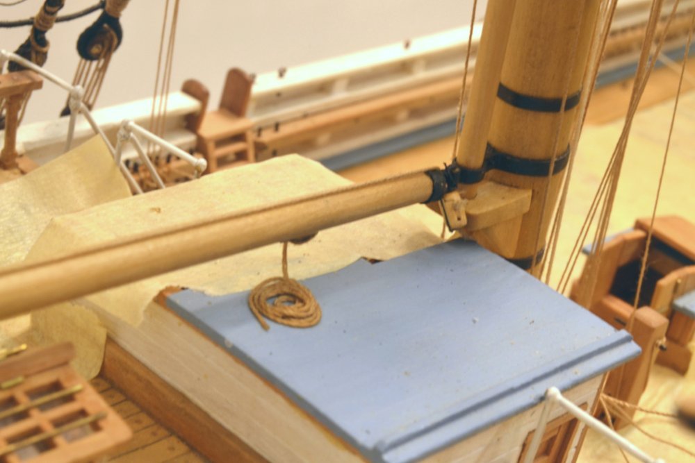
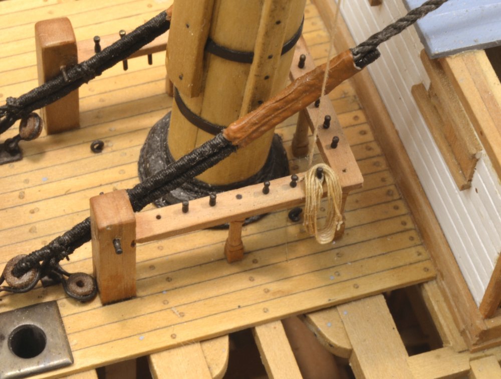
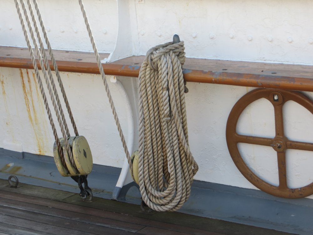
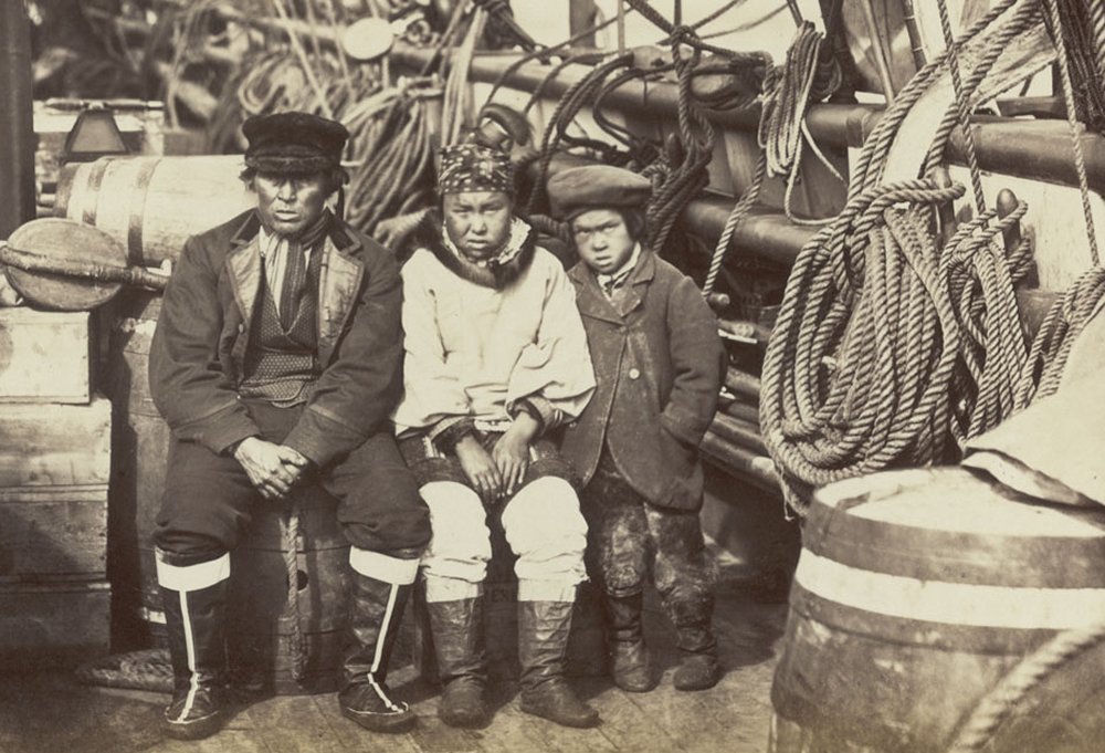
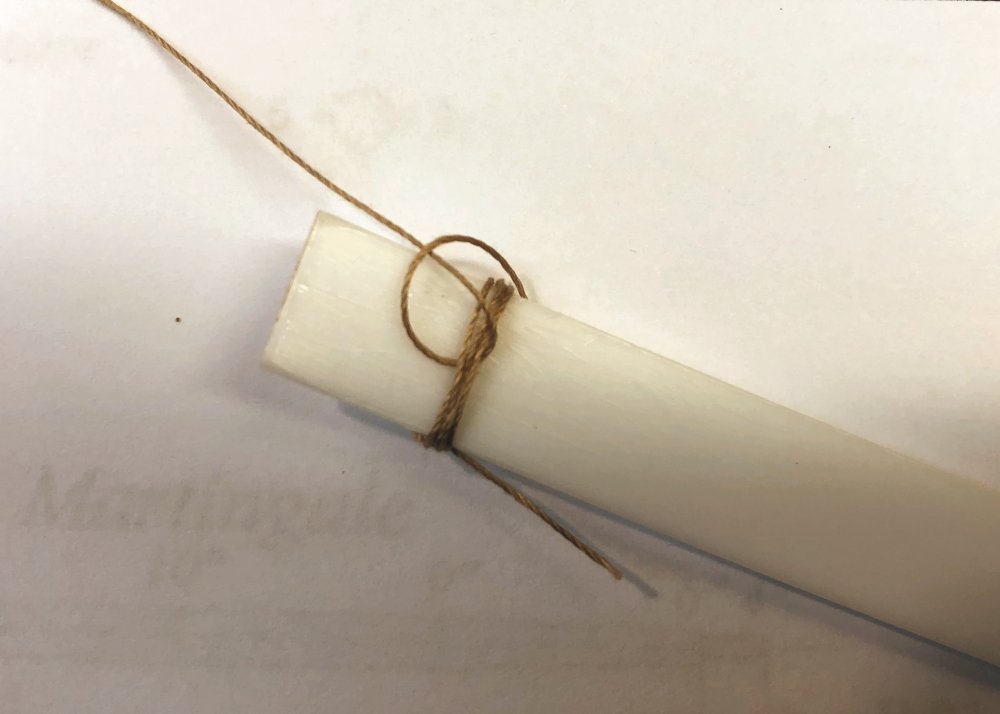
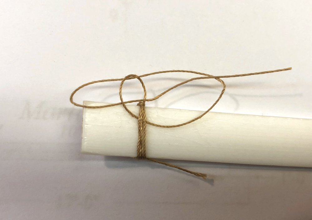
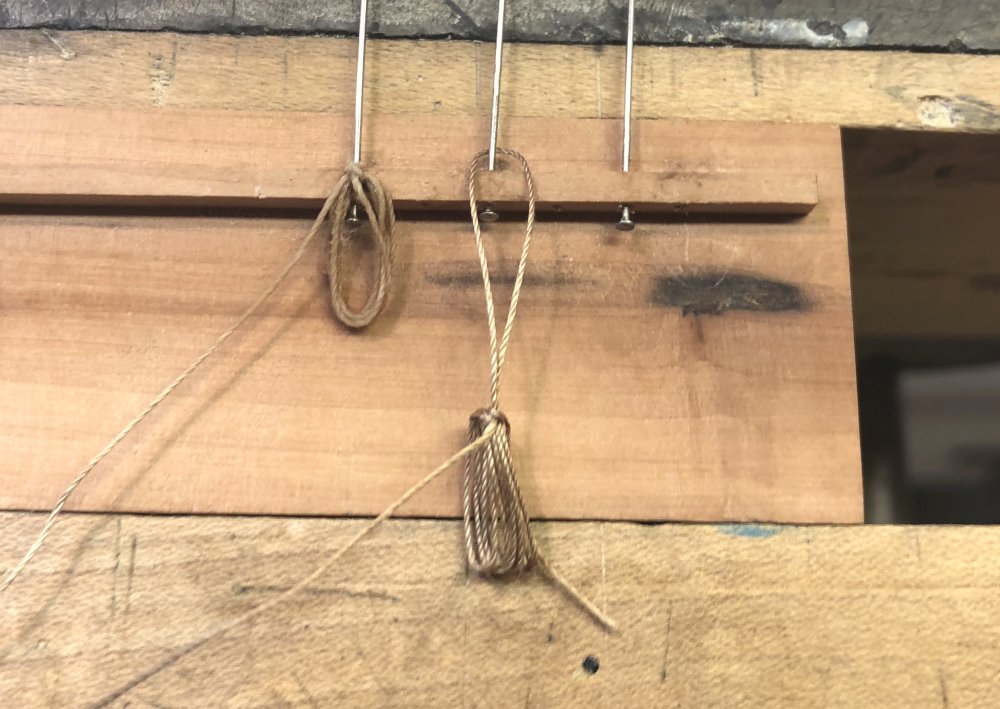
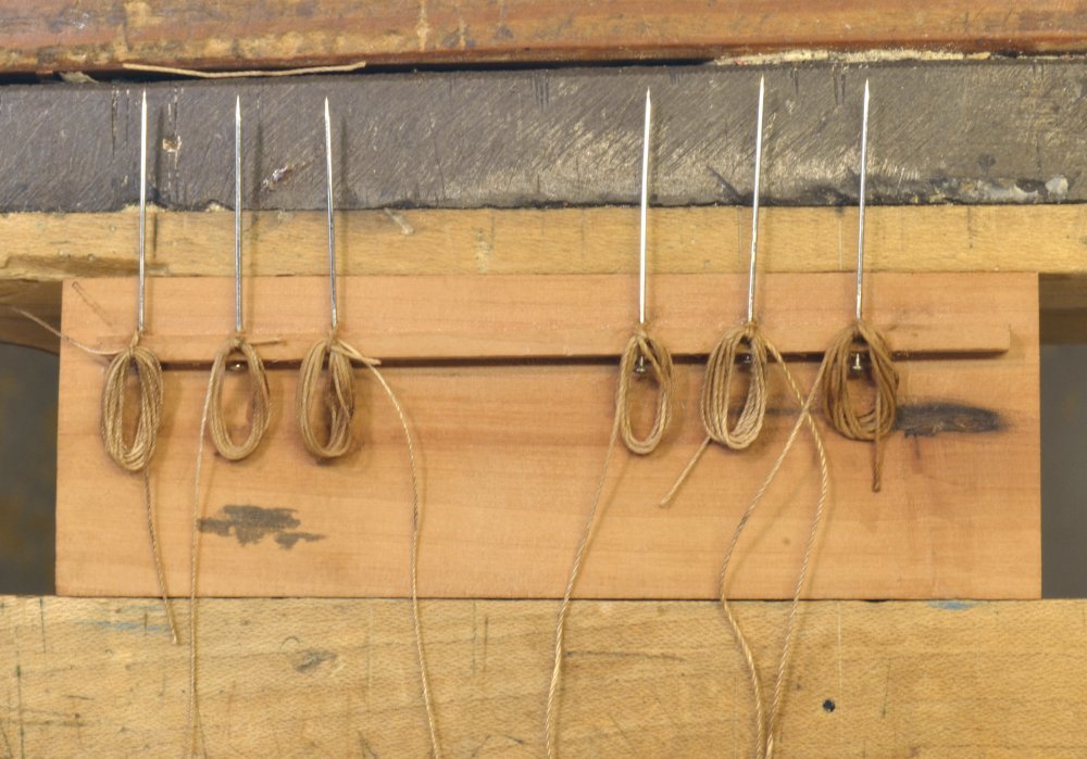
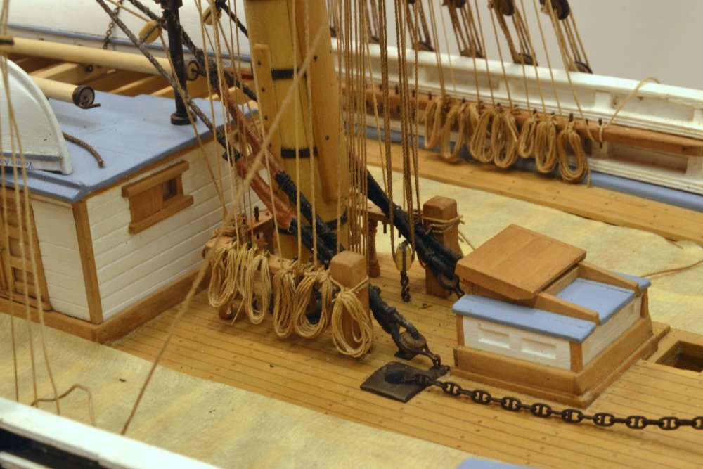
Young America - extreme clipper 1853 Part 300 – Rope Coils I had to take a break from rigging the yards to work on rope coils because access for fitting these is becoming daily more obstructed. Each of the 200 or so belayed lines on the model requires a coil of excess rope to be laid over the pin. It is not practical to use the actual excess line for these, so each ids being made separately and glued over the pin and belayed line. The first picture shows the simplest arrangement in which the coil is merely laid over the pin. In poring over many photos of old clipper ships, this seems to have been the dominant method – without too much care or uniformity applied. While simple to make there are disadvantages. In the picture a sample line is belayed behind the rail – not possible for most lines – making the draping of a large coil awkward, especially for many closely spaced pins like those on the model's main pin rails. My preference has been to use the method shown in the next picture, taken on the Joseph Conrad at Mystic Seaport. In this configuration, commonly used today, the line is belayed with a number of crossover turns on the pin. A coil is then made of the excess rope. The line between the pin and the coil is then pulled through the coil, given a twist, and placed over the pin. The result is a neat coil that takes up minimum space on the rail. However, I was not prepared to adopt this method because of its absence from early photos – until I came across the next picture, taken in the early 1870's. This method is clearly used – none too neatly I may add – on the pins at the right and further back – along with a variety of coil types. This was sufficient evidence. After making a few of these by the method described above and fitting them over pins in confined spaces, I concluded that my life expectancy would not be sufficient to make and fit the required number, especially if my sanity became impaired. So, I decided to make them in the following way, yielding a similar but slightly different appearance. In the first picture a length of line was wrapped around a strip of Teflon and looped under itself to form a single hitch as shown in the next picture. After pulling the hitch tight to hold the coil, the line was passed under the loop again and another looped hitch formed leaving the loop to the left in the next picture. This loop on the left will go over the pin, being secured by pulling the line on the right to tighten the looped hitch. The final tug on this line was made after the coil was removed from the strip and fitted to a pin rail fixture as shown below. The coil on the right is about to be pulled up to look like the one on the left. The next picture shows six of these on the fixture. These have been wetted for pliability and touched with wood glue at the knot. When dry, they can be slipped off, the excess ends clipped, and fitted into place. It takes less than two minutes to make one of these, which suits me just fine. The coils are matched to the rigged line sizes and consist of the amount of rope to be expected given the configuration of each line. The last picture shows installation of these on the foremast fife rail and forward main pin rail. Only close inspection will reveal the extra knot. I am now trying to install these as each line is finally tensioned and the belayed loops glued. The forward pin on the port rail is for the lazy tack, which is still kept loose until the lower course sheets are rigged – so no coil yet.. Ed
- 3,618 replies
-
- 44
-
-
- young america
- clipper
- (and 1 more)
-
Hi Greg, I have not used silk, but I am aware of it. If my math is right .1mm = (.1mm/25mm/inch)= .004" or at 1/72 slightly less than 1" rope. I don't have anything that small, so it does not help me much for rope. I have thought about it for lashing, serving and seizing, but have not tried it. Is their also an issue with life? I thought I read or heard that somewhere. Rob, if what you think "looks right" doesn't agree with reasonable measurements, I would be cautious. But that's me. Ed