EdT
-
Posts
2,214 -
Joined
-
Last visited
Content Type
Profiles
Forums
Gallery
Events
Everything posted by EdT
-
Thank you all for these comments and likes. Wefalck, as you say, placing a bit of card behind the shrouds is most helpful and I have done that where other rigging permits - another good argument for getting the ratlines on early in the process. When I started on the ratlines, I gritted my teeth and decided to form lashing eyes at each end, recognizing that this would be a major effort - especially at this scale where ratlines are No. 80 cotton (~.007" diam.) thread. I described the method for this in Part 283. Other parts describing stages of the ratline work are also described in Parts 213,228, and 240. Some of the methods evolved as the work progressed but Part 283 describes the lashing of eyes most clearly. To my regret, I could not manage this on the fore topgallant shrouds shown in the last part because other rigging denied access for my finger behind the shrouds. I find this necessary to steady the ratline so the needle can be passed through it to form the eye. Virtually all the other ratlines have eyes at both ends. A lesson on sequencing the work. Michael, thank you. Longridge has always been my hero. I believe he did go this far - at least he describes this level in both his books - the first on his Cutty Sark model built in the early 30's and the second on the Victory model that followed. I cannot recall ever seeing his Cutty Sark, but the book on that model would be an indispensable resource for building that oft-modeled ship - and it was of use to me in designing the Young America rigging. Harold Underhill, a major source for me, seems to have been a major contributor to The Longridge clipper book. He did the drawings and perhaps the diagrams in the text. There is great similarity to his book - and equal level of detail. All I can say about keeping track of all these lines and avoiding a complete tangle is - one at a time wherever possible, and diligent reliance on the (indispensable) rigging list - and oh yes, frequent breaks from the work. Thanks again, everyone. Ed
- 3,618 replies
-
- 7
-

-
- young america
- clipper
- (and 1 more)
-
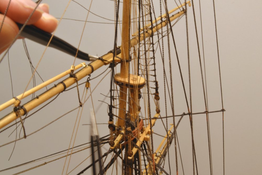
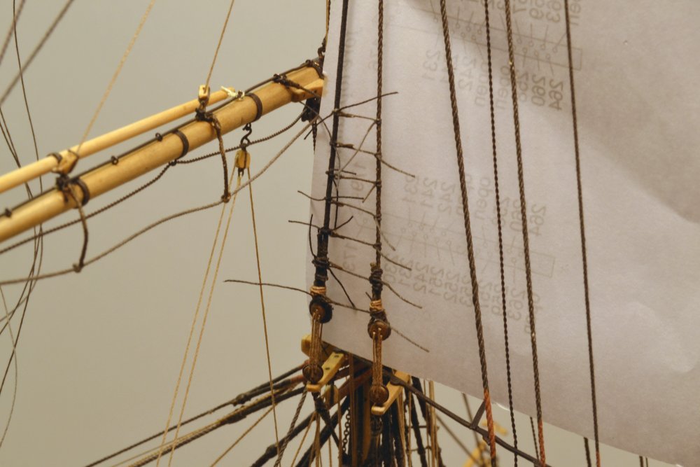
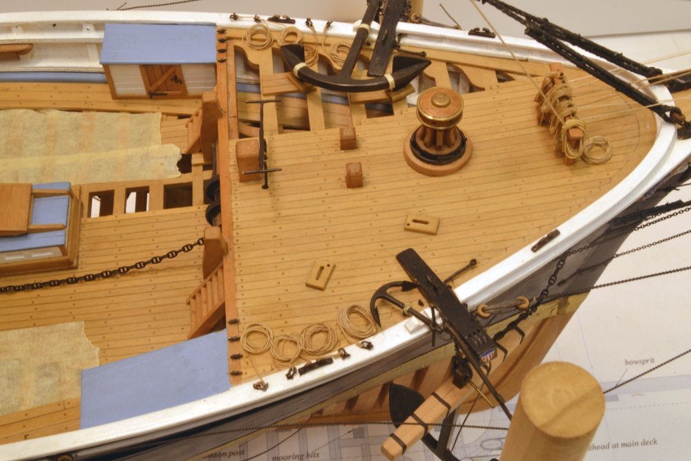
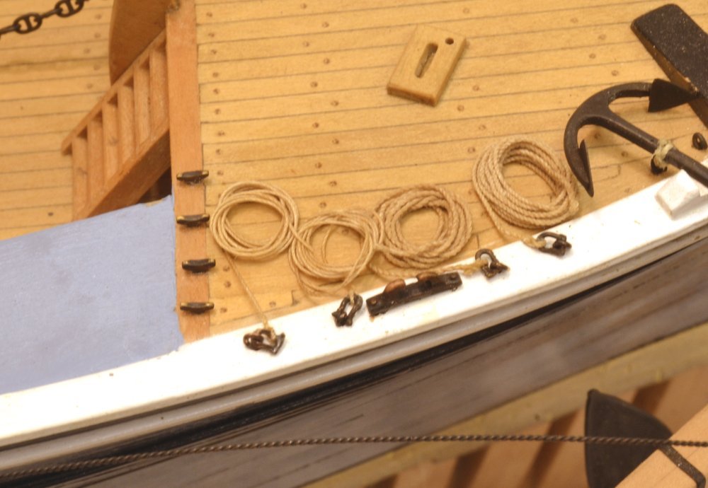
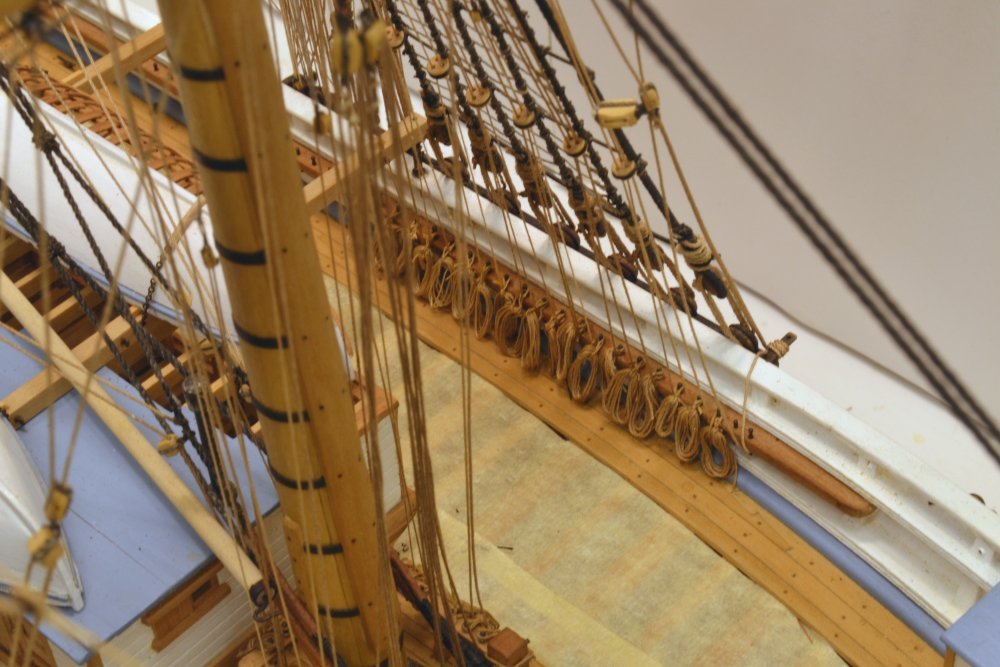
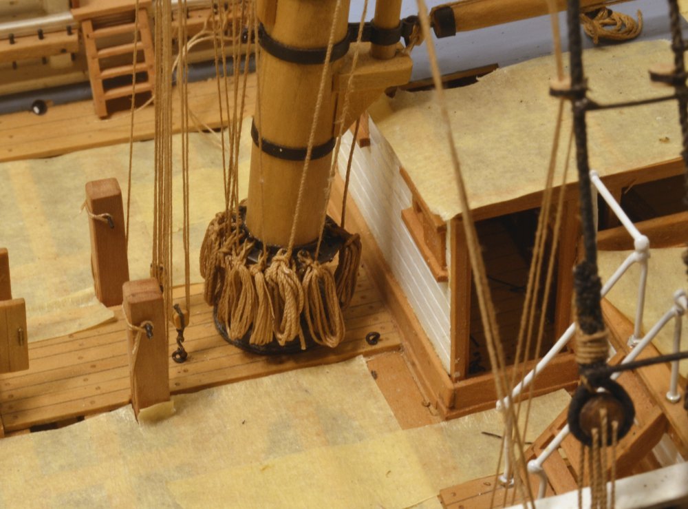
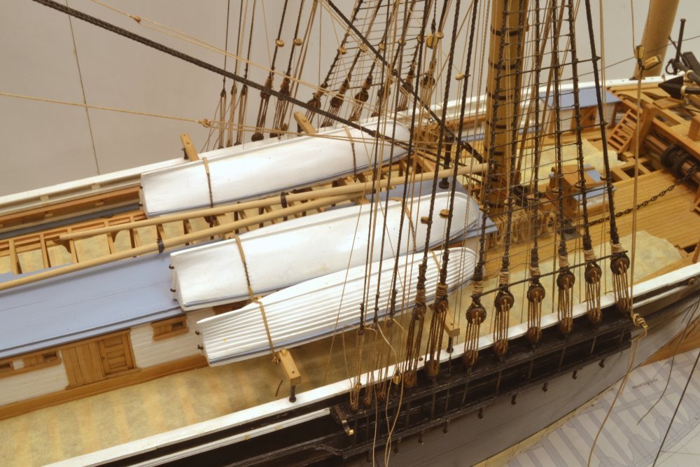
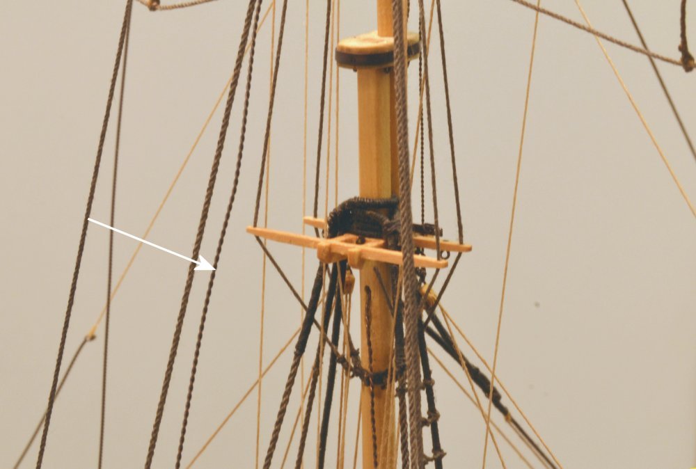
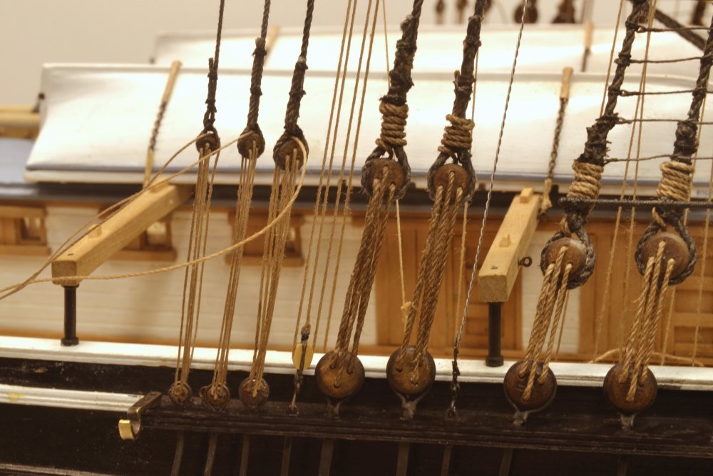
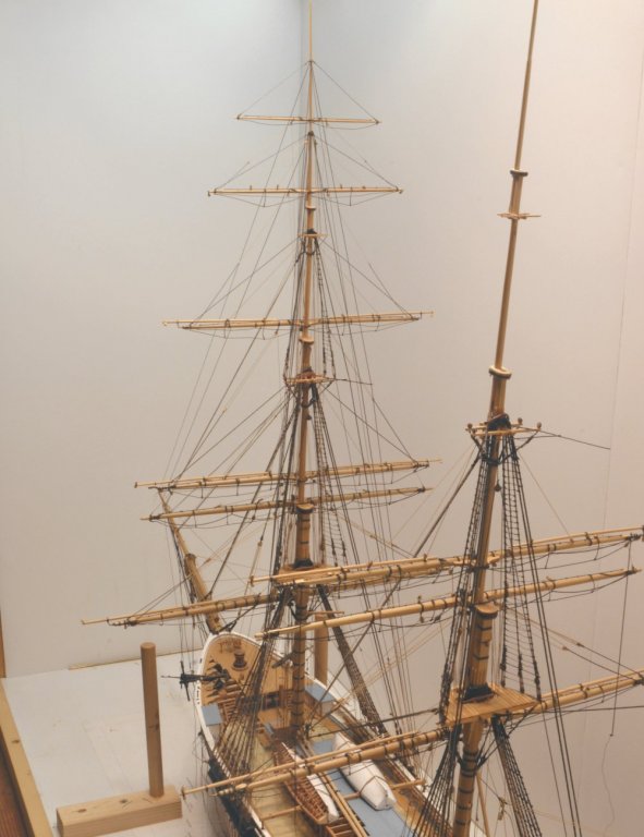
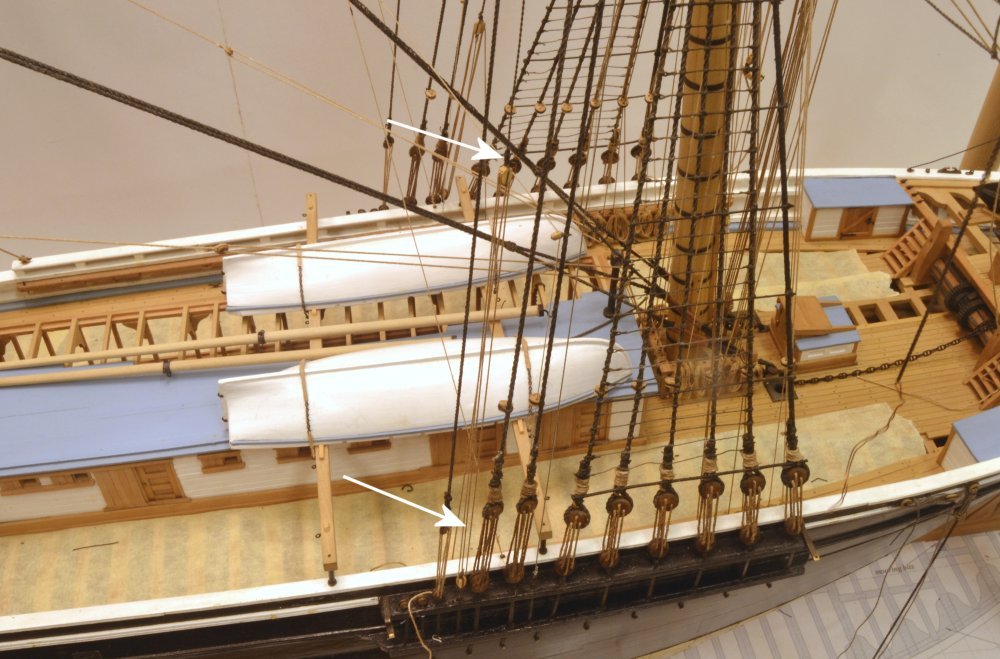
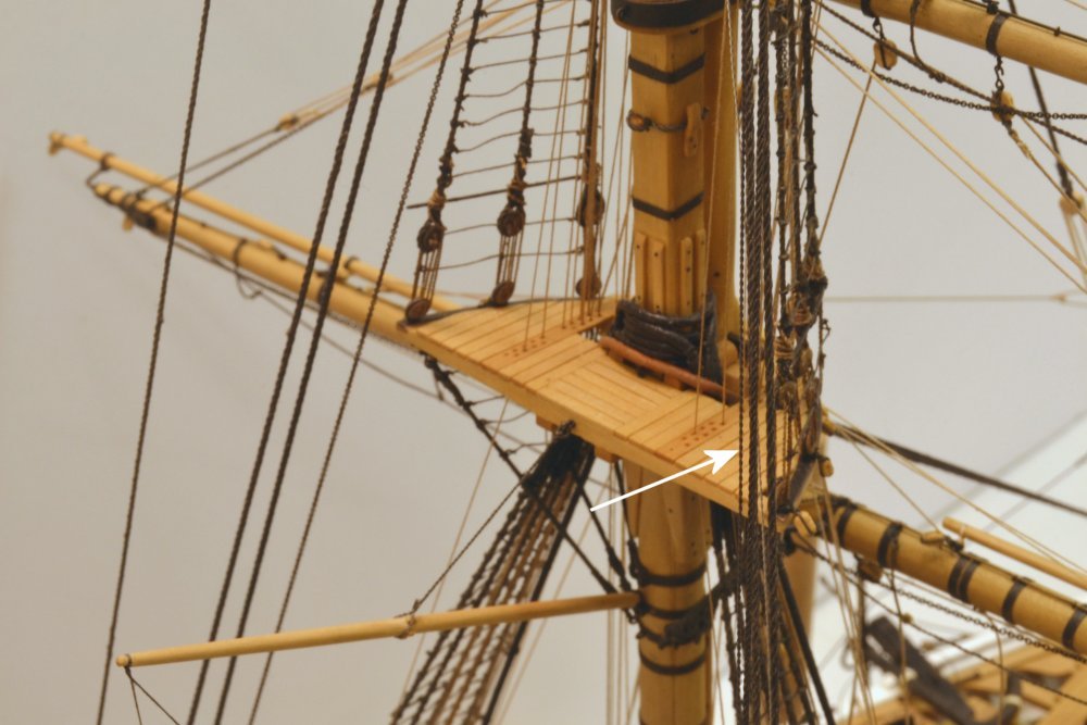
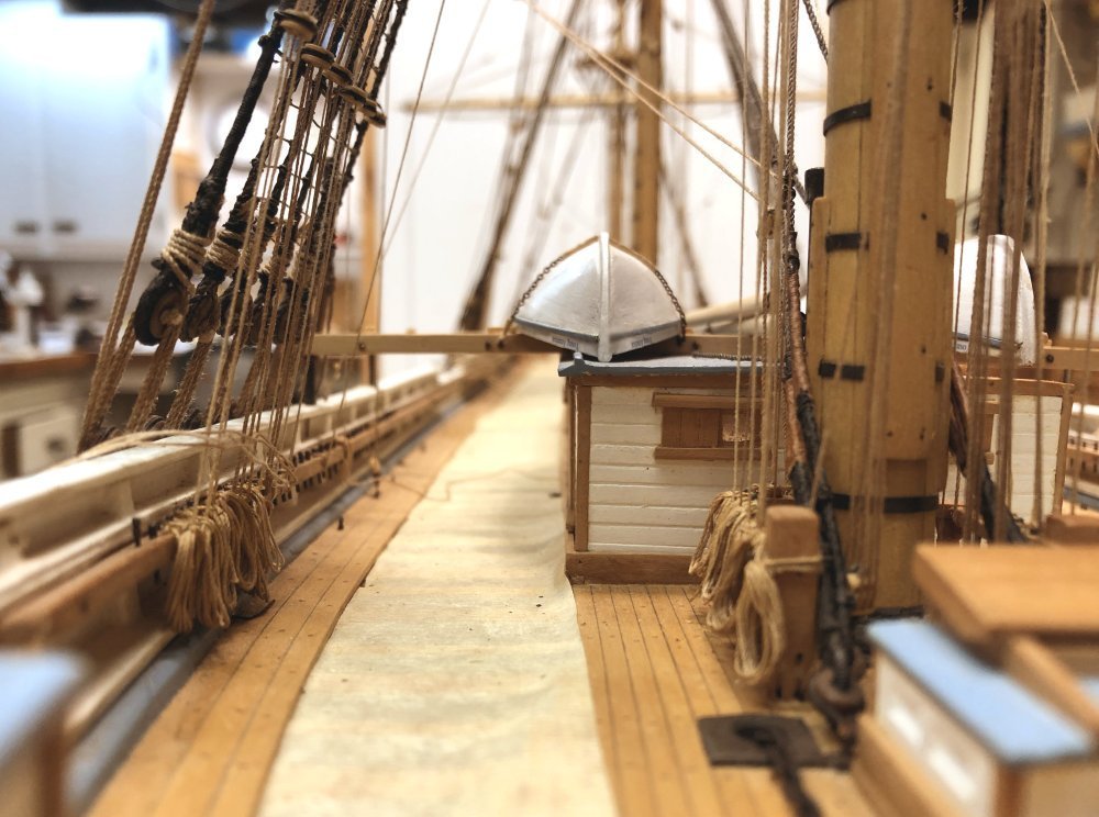
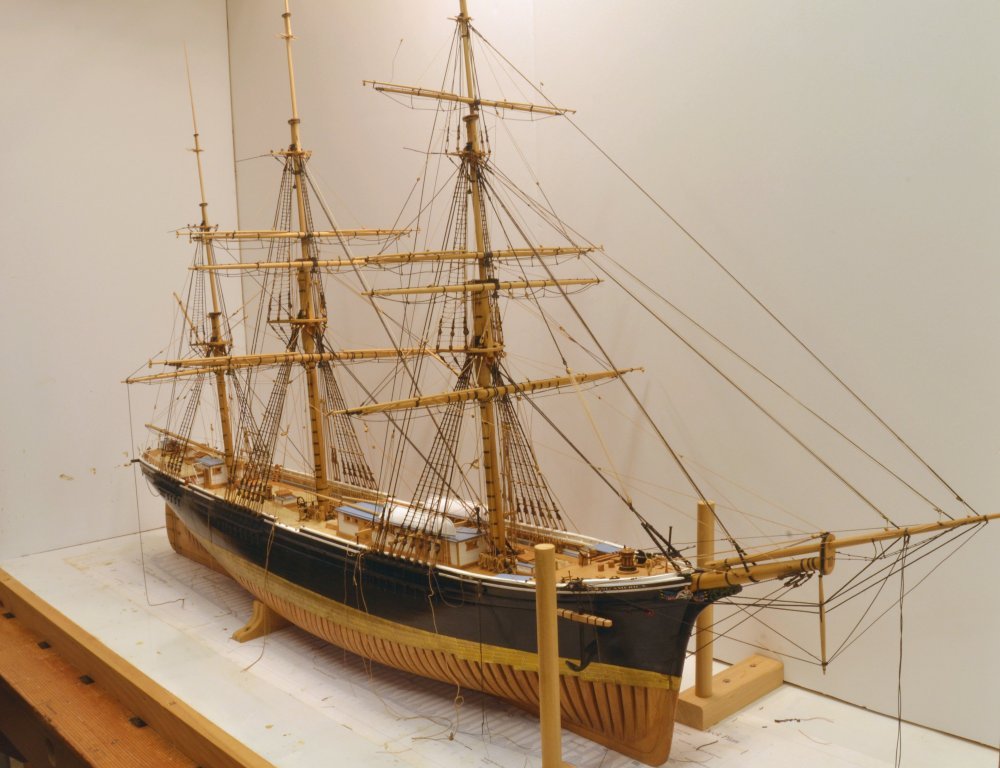
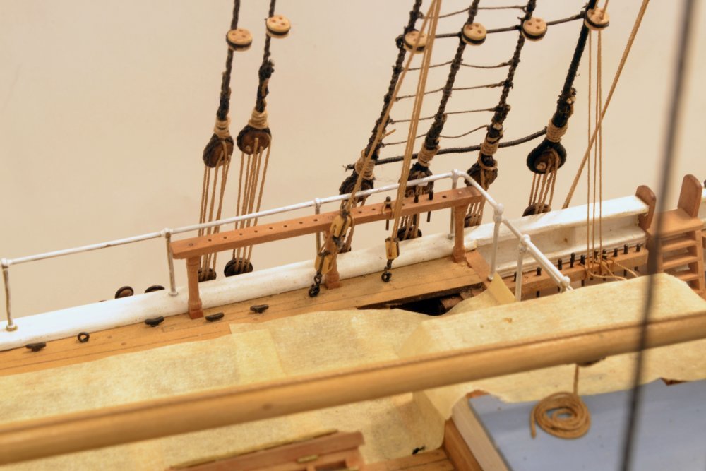
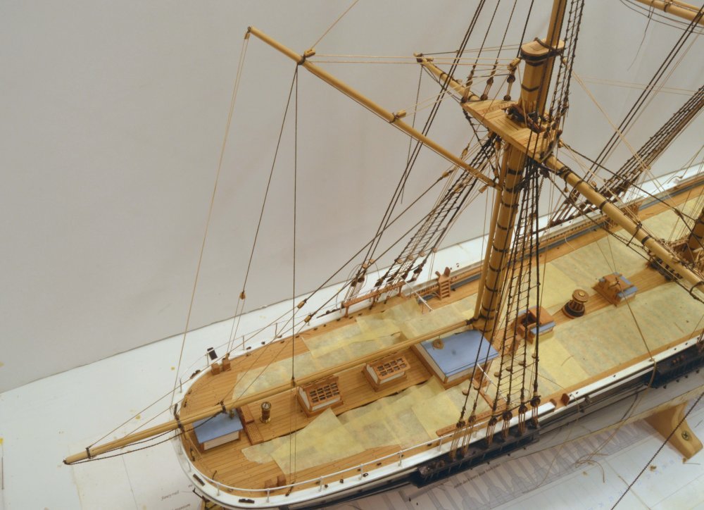
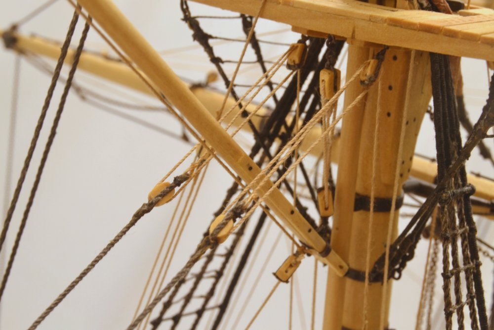
Young America - extreme clipper 1853 Part 310 – Some Loose Ends In moving the main rigging installation forward, some finishing-up work inevitably got bypassed to be done later. Some of this was for access reasons, some to escape prolonged tedious tasks – for example, the seemingly endless "rattling down." Sometimes this multiplies the work, as in the first picture, where topgallant ratlines are being lashed after surrounding lines were installed. This should have been done earlier, right after the tg crosstrees were installed. In the picture one of the ratline eyes is being lashed to the forward shroud. Two pairs of tweezers are being used. The blur in the picture is due to shaky hands. Use of a paper shield like the one in the next picture, helps avoid lashing down other rigging and helps visualize the work. On these tg shrouds, where the work is obstructed, the second ends were clove-hitched due the difficulty of forming lashed eyes that were used on the lower and topmast ratlines. In addition to the upper ratlines, those on the lanyards and the futtock shrouds below must also being added. Fortunately there were no ratlines on the royal shrouds. The next few pictures show the addition of the jib sheets on the forecastle. Each of the four jibs has a sheet on either side. Each sheet reeves through a double pendant middle and seized to the sail's clew cringle. The standing ends of these sheets are shackled to eyebolts on the rail. After they pass through bullseyes in the pendants they are belayed on cleats on the forecastle breast rail - with the sheet on the weather side taking the strain of the sail and the lee side slack. Lacking sails, the eight sheets are simply coiled on the forecastle as shown in the first picture. Coils for the jib downhaulers were also added to the forecastle rail to the right. These are large coils because the long downhaulers are fully hauled in with no sails. The next picture shows the "off-site" fabrication of the sheet coils. The lines were first spliced to eyebolt shackle assemblies, then wrapped around the plastic rod, then wetted with diluted glue and slipped off to dry. As with most of the rope coils on the model, the lengths approximate requirements of the line. The next picture shows the coils glued to the deck on the starboard side. The two on the right, for the staysail and the inner jib, are 3 1/2" and 3" rope respectively. Those on the left, for the outer and flying jibs, are 2 ½" rope. The next picture shows rope coils for the foremast rigging on the port pin rail. Altogether there are about 60 coils associated with the foremast running rigging – on the port and starboard rails and the fife rails – excluding those for the yard braces and other deferred lines that will be added later. This picture also illustrates the role of the shroud fairleads in organizing the lines. I'm sure these also assisted in line identification. The next picture shows most of the coils on the mizzen spider band, those associated with the rigged lower yards and the spanker. Finally, after completing the belaying between the skid beams, the cutter was retrieved from storage and lashed down as shown below. The other cutter will be hung from the quarter davits on the starboard side - later. I have yet to decide where to place the two lower studdingsail booms lying on the cabin roof in this picture. Also, lanyards on the last three backstays on each side, like the fore course sheets and tacks at the far right of the photo, have yet to be secured. Ed
- 3,618 replies
-
- 35
-
-
- young america
- clipper
- (and 1 more)
-
I don't doubt it, Druxey. I am old enough to remember when construction workers on UK job-sites wore ties. I can specifically recall one cement finisher, some pipefitters, and a few insulators. Cheers. Ed
-
HMS ROYAL KATHERINE 1664 by Doris - 1/55 - CARD
EdT replied to DORIS's topic in - Build logs for subjects built 1501 - 1750
I am catching up, again, Doris. Thank you for posting these magnificent pictures of your work. The sculpting is beyond any words I could offer. Just amazing. Ed- 1,035 replies
-
- 7
-
-
- royal katherine
- ship of the line
- (and 1 more)
-
Neither. You may need to look closer, Rob. They may be seen on the 7th photo in the above post - just barely. The fore downhaulers are described and shown more clearly in Part 274. these lines are shackled to the top yard arm band on the lower topsail yard, pass up through blocks on the upper yard arm, run across to the quarter blocks then down to belay on deck. Ed
- 3,618 replies
-
- 2
-
-
- young america
- clipper
- (and 1 more)
-
Thanks, again, everyone. Mark, its good to see you back on deck. Your comments are always well appreciated and the posts on your log always add items and methods of interest. Pat, the complexity of lines on a ship like this - with 18 square yards - can be a bit daunting and trying to include a maximum number on the model may seem insane. If you view the ship as a complex machine as well as a thing of beauty - as I do - that is perhaps a reason to go to those lengths. Describing this for others is a challenge. So far, the method and information I have settled on for that seems to be working and my use of it for construction will let me hone it for use by others. I have started to bring this together in initial drafts, but there is still much to do with that - and on the model. Ed
- 3,618 replies
-
- 2
-
-
- young america
- clipper
- (and 1 more)
-
No, its much too common an occurrence - more like calm resignation. Muttering is reserved for things that break.
- 3,618 replies
-
- 7
-
-
- young america
- clipper
- (and 1 more)
-
Thanks everyone, for the likes and comments. A lot of lines, Druxey - and no studdingsail rigging - 100 or so lines wisely left off. There is more than enough opportunity for fouled lines, and many have been run more than once - especially as we move skyward. The fairleads in the top and on the shrouds help a lot, but that does mean if a line has to be rerun it must be pulled back through the fairleads, rerouted and threaded through them again - tweezer work. Getting through the upper shrouds and futtocks in straight runs has also been fun. So far, the belaying plan has held up, with only a few revisions - to my great relief. There was a logic to this that could only have evolved over time and by experience. Micheal, making this understandable in one book will be a challenge for sure. Ed
- 3,618 replies
-
- 3
-
-
- young america
- clipper
- (and 1 more)
-
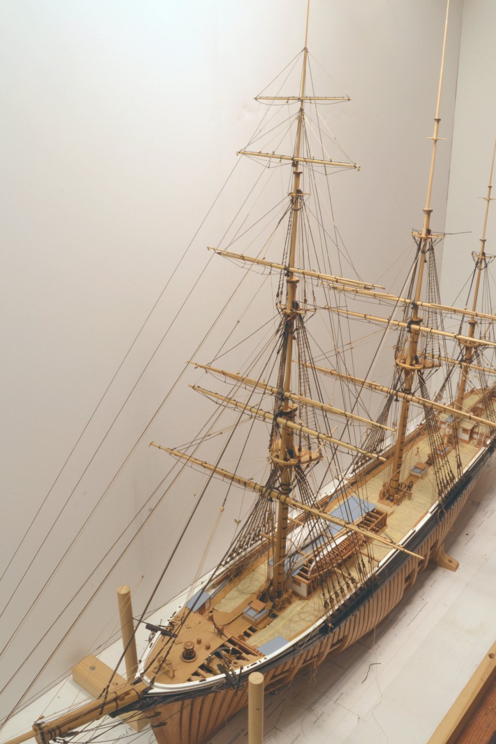
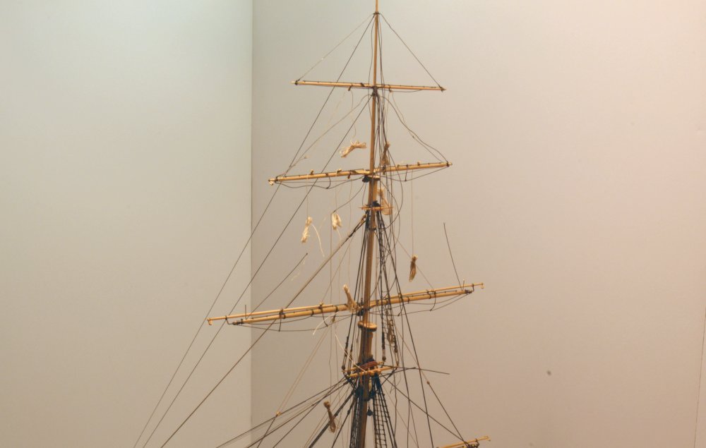
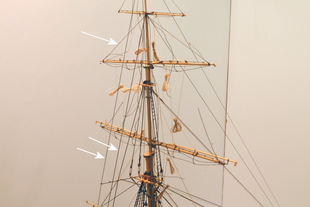
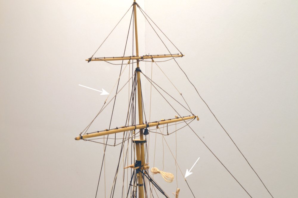
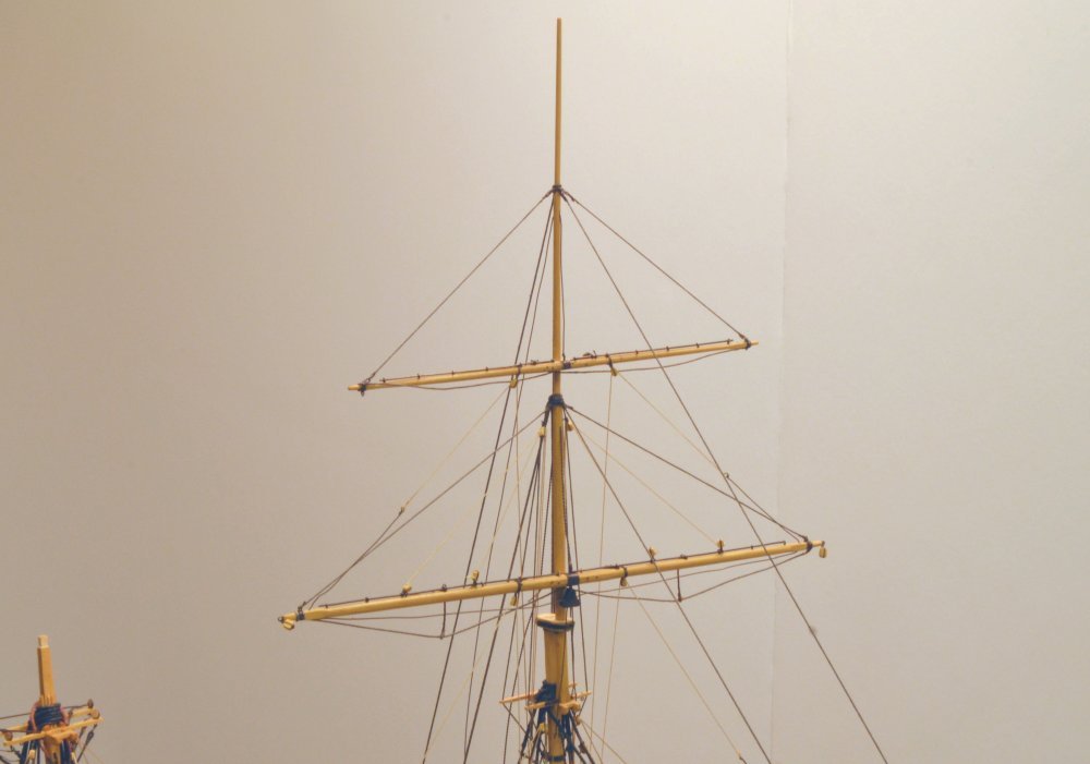
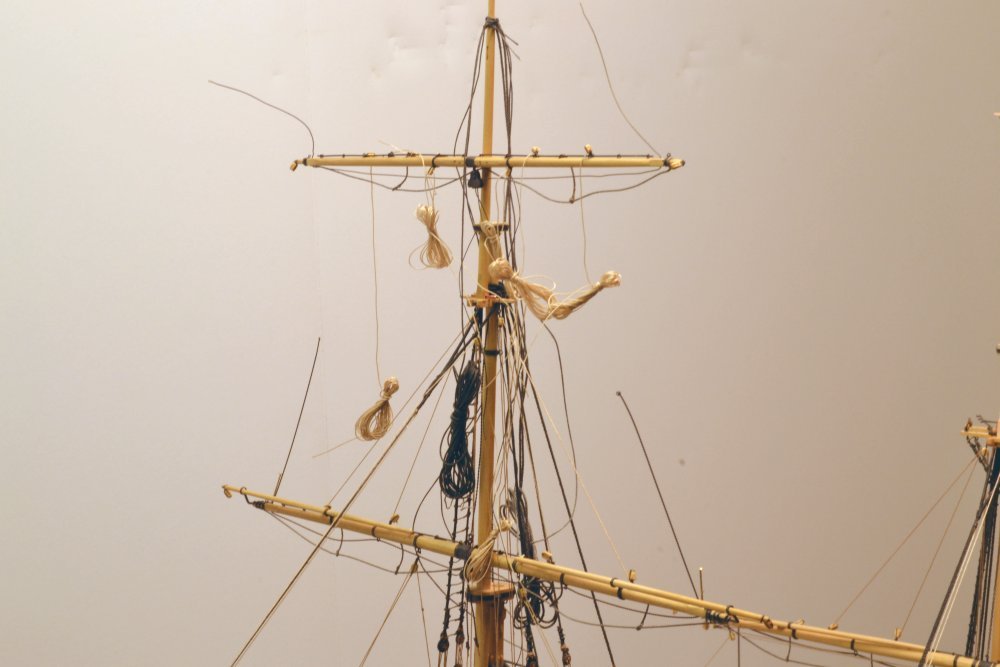
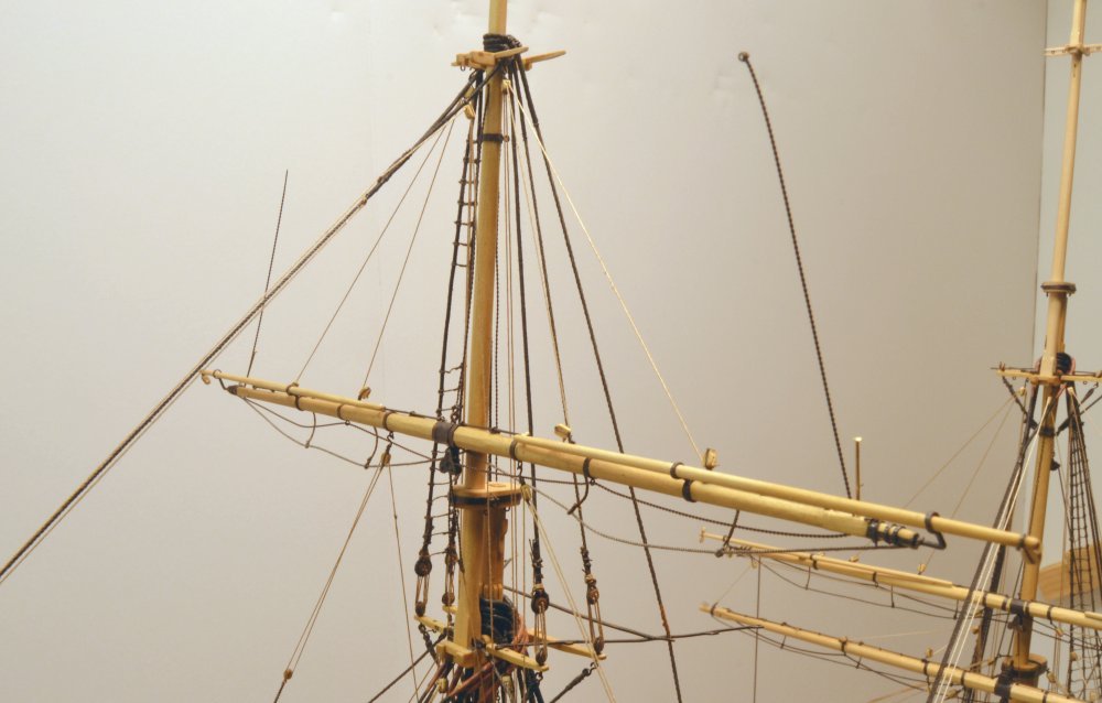
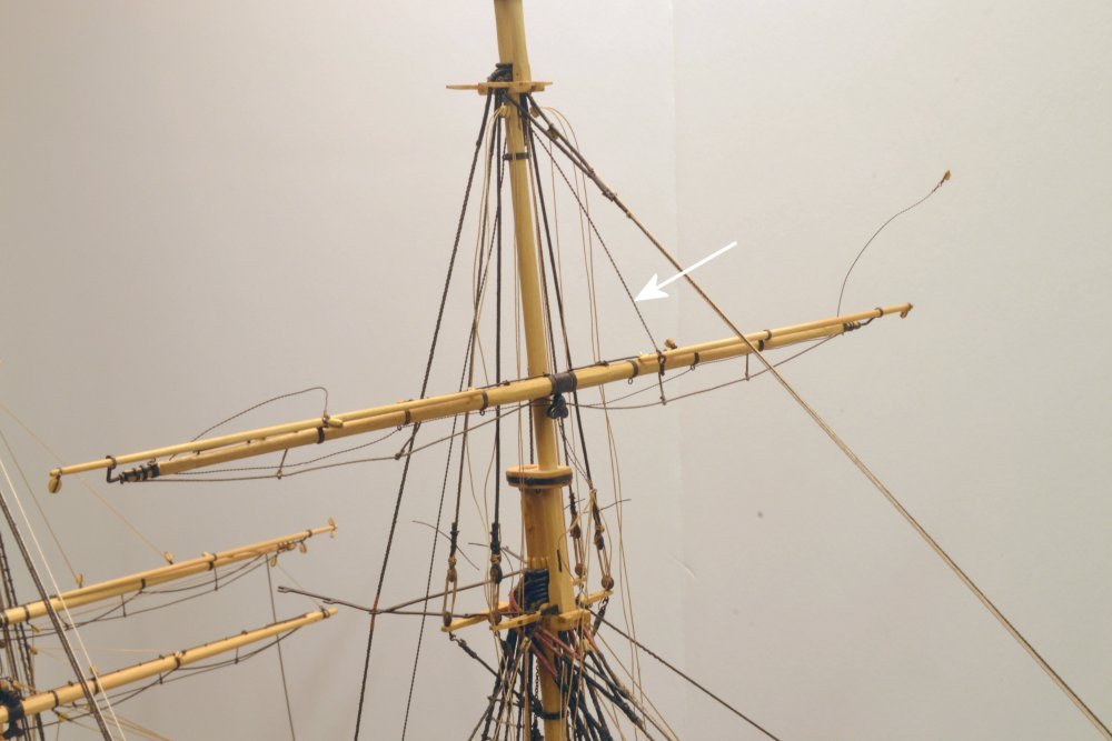
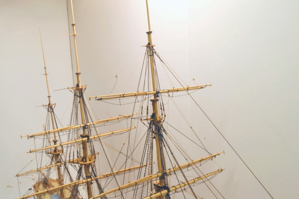
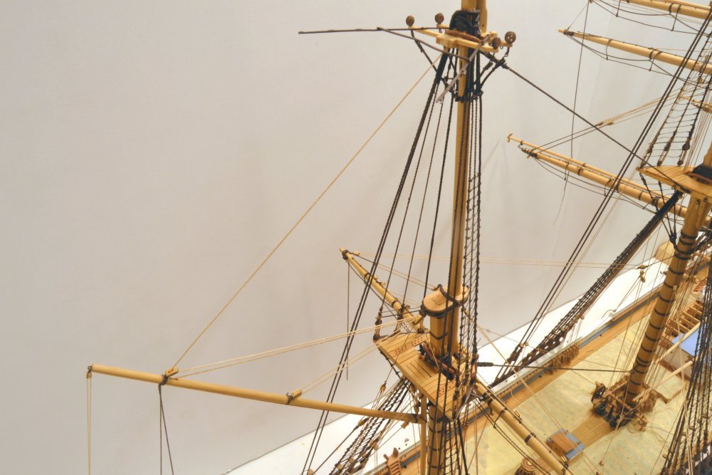
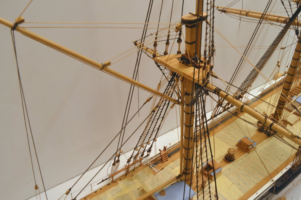
Young America - extreme clipper 1853 Part 309 – Foremast Top-hamper 2 I mentioned in the last post that the topmost pole mast and the two upper yards were to be installed with most of the rigging fitted at the bench. The first picture shows the assembly erected on the topgallant crosstrees. The two forward stays – the royal and the skysail – have been threaded down through the bowsprit, but most of the other lines are dangling in a tangle - as yet unconnected. The running rigging lines – clew-lines, buntlines, leechlines, and skysail sheets – all of which are quite long - are coiled to avoid a real tangle. The next step was to run the standing rigging lines to their connection points to clear some of the mess. In the next picture the lifts on the two upper yards are rigged and the backstays for the upper mast sections have been run – but not yet connected. The arrows point to the royal standing lift, the royal backstay and the skysail backstay on the port side. In the next picture the skysail sheets below the royal yard have been run and the clew-lines for both yards are being rigged. These lines serve to pull the yards down on the lifts. Arrows point to the clew-lines that attach to the chain sheets. All these lines pass down through the fairleads in the top and belay on the main deck rails. Once the yards were held down, the halyards were passed through their mast sheaves and secured to their central sling bands on both yards. In the next picture the arrow points to the dangling royal halyard chain that runs down from the mast sheave, and will eventually be connected to a tackle to the deck. This picture also shows the royal shroud pairs. These run from the masthead down through holes at the ends of the crosstrees and are seized to eyes on the topgallant mast band in the lower part of the picture. The next picture shows the upper mast backstays connected to the deadeyes on the starboard channel Starting from the skid beam and working aft, the channel connections are – the wire for the standing end upper topsail halyard, the two topmast backstays, the tackle block for the skysail halyard, the topgallant backstay, the royal backstay, and finally the skysail backstay. The deadeyes and lanyards on these standing lines decrease in size down to 6" diameter and 1 1/2" rope size, respectively. The lanyards on the last three backstays will be tied off later once the tensions are set – and the mast made vertical. The next picture shows the bunt and leechlines rigged on the royal yard. The skysail has only lifts, halyard and clewlines. Except for the truck at the top of the mast, some neglected ratlines on the topgallant shrouds, and a couple dozen rope coils on the pin rails, the foremast rigging is now complete. Braces are being saved for last. The next two pictures show the mast at this stage. This was a lot of rigging to sort out. I hope the descriptions are not too confusing. On the remaining masts I will use this same process, but leave off the clew, bunt, and leech lines to be done in place. Coiling these small cotton ropes results in a lot of fuzz when they are untangled and stretched out. I had to replace a couple. Rigging these in place reduces this problem. I have also begun treating cotton lines with diluted pva to further reduce fuzz. More on this later. Ed

- 3,618 replies
-
- 35
-
-
- young america
- clipper
- (and 1 more)
-
Welcome to the forum, Ab. I know I am speaking for many others here when I say that it is an honor to have you join us and share your wealth of knowledge and experience. Like many others, I have immensely enjoyed your book and drawings on Dutch Merchant Ships. I look forward to your contributions here. Ed
-
Paul, what are you using for sanding sealer? There are many varieties. Titebond glue is resistant to most finishes, but as we know, our favorite "ungluer" - isopropyl alcohol - will soften it - and probably swell it in the process. Perhaps the sealer had this effect. Also, if the glue joints on the curved hull were not tightly fit and the gaps filled with glue, that would be different from your tightly matched straight joint lines on the test piece. Another possibility: you mentioned dark glue. Is this purchased as dark glue or coloring mixed into the normal Titebond. If the latter, what is the colorant? Which grade of Titebond? Just some other things to consider. Ed Added note: Apologies, Paul, I see you have already answered some of these questions and I missed that. I would say that the alcohol-based sealer is a prime suspect, especially if the joint gaps were filled with glue.
-
Rabbet cutting question....
EdT replied to CPDDET's topic in Building, Framing, Planking and plating a ships hull and deck
The posts starting on this page may be of some assistance: Ed -
Thanks for the suggestions, Druxey. Arm fatigue is one problem, shaky, unsupported hands are the major issue. I actually have an adjustable arm support beam that clamps to the case on either side or at any height or at varying distances off the center line and I use that frequently, but probably haven't had it in any of the pictures. Even with that available, maximizing the work on the bench seems desirable - goes faster and is easier - but the entangled web on the assembly has to be sorted out or somehow minimized - working on this latter problem. Still a lot of work to do aloft. So far, I am liking this method. Ed
- 3,618 replies
-
- 6
-
-
- young america
- clipper
- (and 1 more)
-
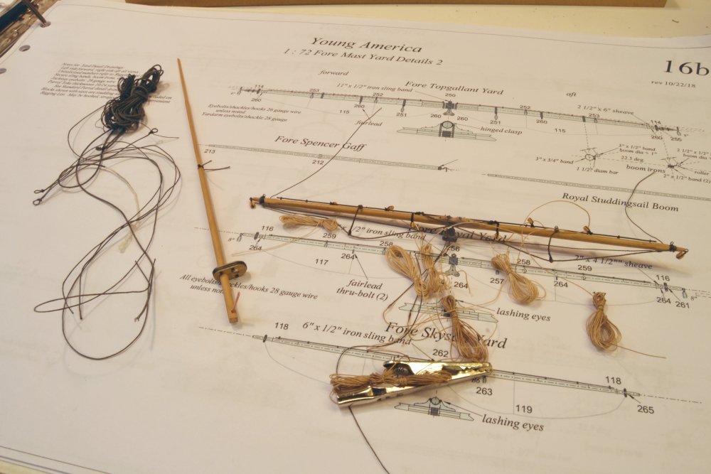
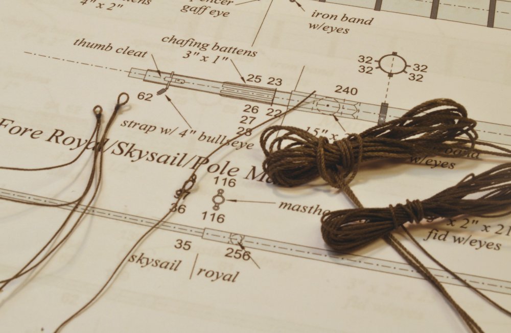
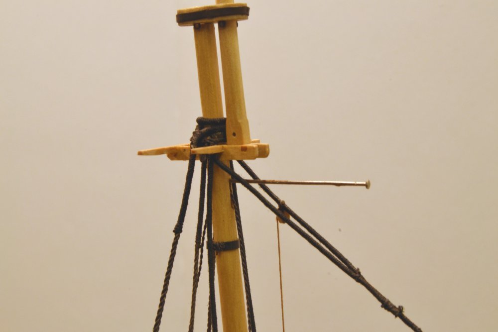
Young America - extreme clipper 1853 Part 308 – Foremast Top-hamper I will use the term "top-hamper" to refer to the upper parts of the masts. That is, the royal/skysail/poles, the royal and skysail yards, plus the associated rigging. I do not much care for this term, but it was commonly used at the time and will make my descriptions more concise. These parts are being discussed together because I expect to prefabricate the entire assembly complete with most of the rigging on the workbench before mounting the whole assembly on the model. Hopefully this will reduce the strain of assembly on the upper masts where most of the work is small and above my shoulder height. The first picture shows the pole mast and the royal yard with some of rigging lines. The skysail yard and its rigging has yet to be added to this array. In additional to rigging normally fitted at the bench on normal yards – the foot ropes, sheet chains, and blocks – the yard bench assembly includes reeving and connecting the standing lifts, buntlines, leechlines and the royal sheet falls that were rigged after erection on each lower yard. The next picture shows the standing rigging of the royal pole section of the mast. From right to left are the two shroud pairs, the two-eyed masthead strop for the royal standing lifts, the doubled backstays and the fore royal stay. All these lines are coiled to avoid – or at least minimize - a major entanglement. The next picture shows the mast temporarily set with the royal components attached. This assembly was then removed so a similar amount of rigging for the skysail could be added before final erection. The skysail yard that will be fitted to the upper part of the assembly is shown in the next picture after blackening of its copper work. Ironwork on this yard is minimal, just the sling band and the jackstay stanchions. Because this is the highest yard there is no sheet block under the center band. The four shackles for the yardarm bands are shown to the right of the penny in this picture. The 2.7" diameter arms (.0375" at 1:72) on this spar are too small for the banding described in Part 307, so they were fitted using black rope strapping to simulate the iron bands. The next picture shows the yard with the shackles and banding, as well as the jackstays fitted. The rigging for this spar, plus the standing rigging for the skysail section of the mast will next be added before the mast is set. Ed
- 3,618 replies
-
- 30
-
-
- young america
- clipper
- (and 1 more)
-
Rob, put the ends of a length of wire in a vise, loop the bight over a hook in a a hand drill, maintain moderate (not too much) tension, turn the drill to make the chain. Wire size about the diameter of the wire on the chain. Number of wire turns = number of links in that length of chain/2 - approximately. Each turn represents two links. Ed
- 3,618 replies
-
- 4
-
-
- young america
- clipper
- (and 1 more)
-
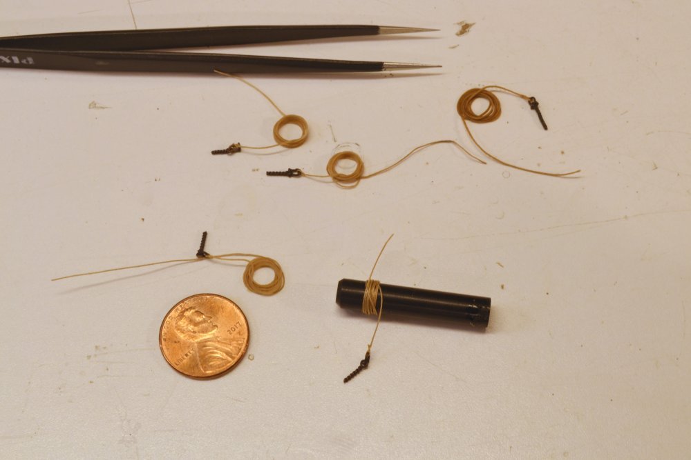
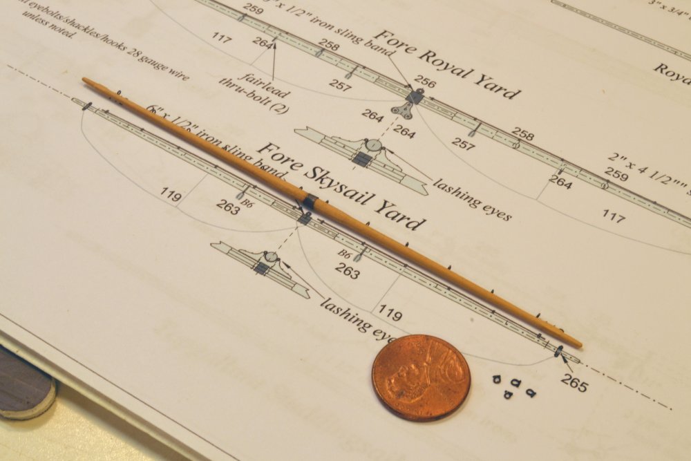
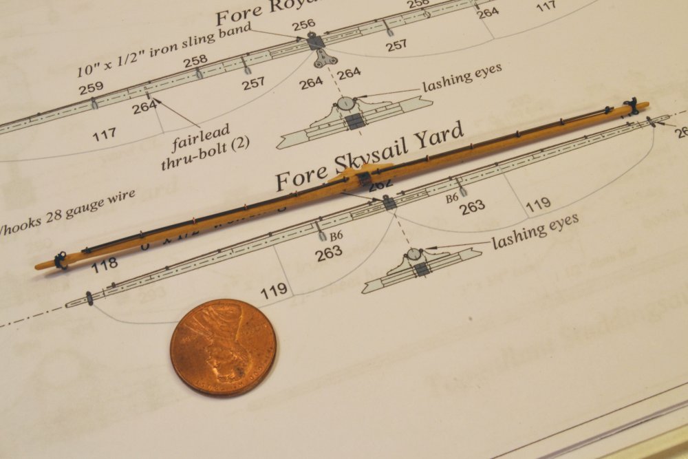
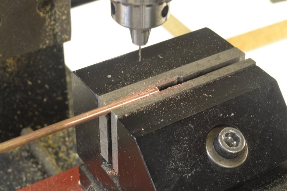
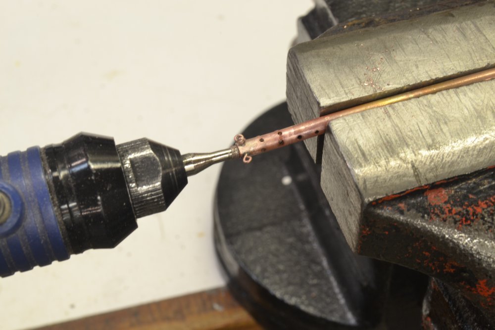
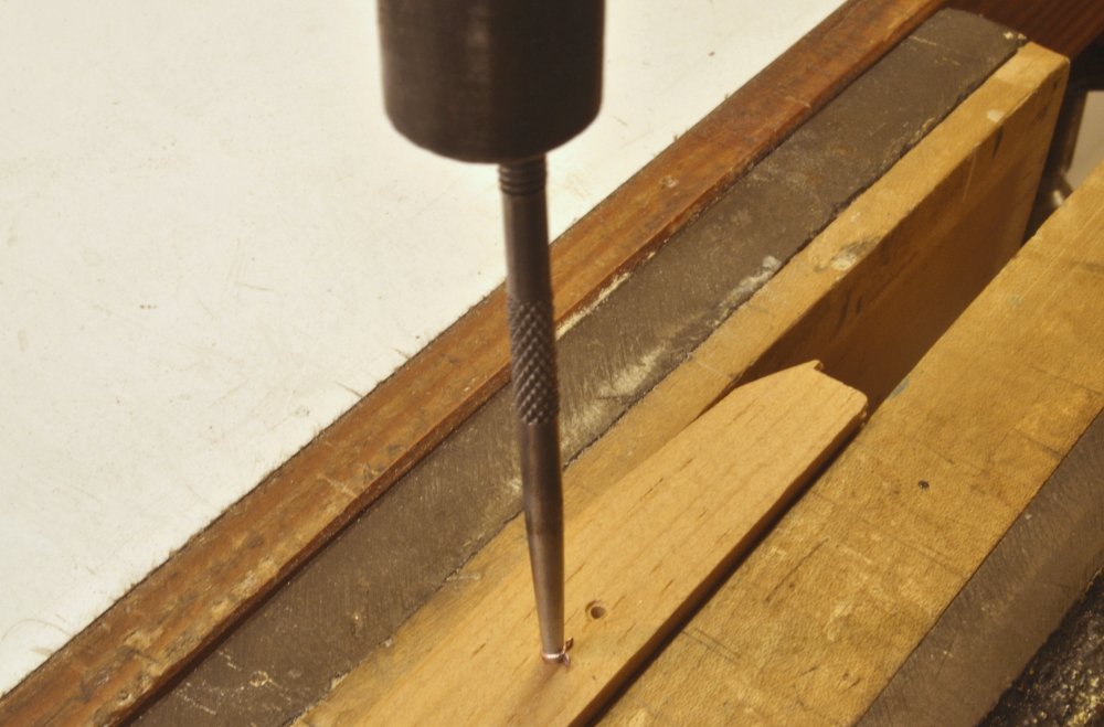
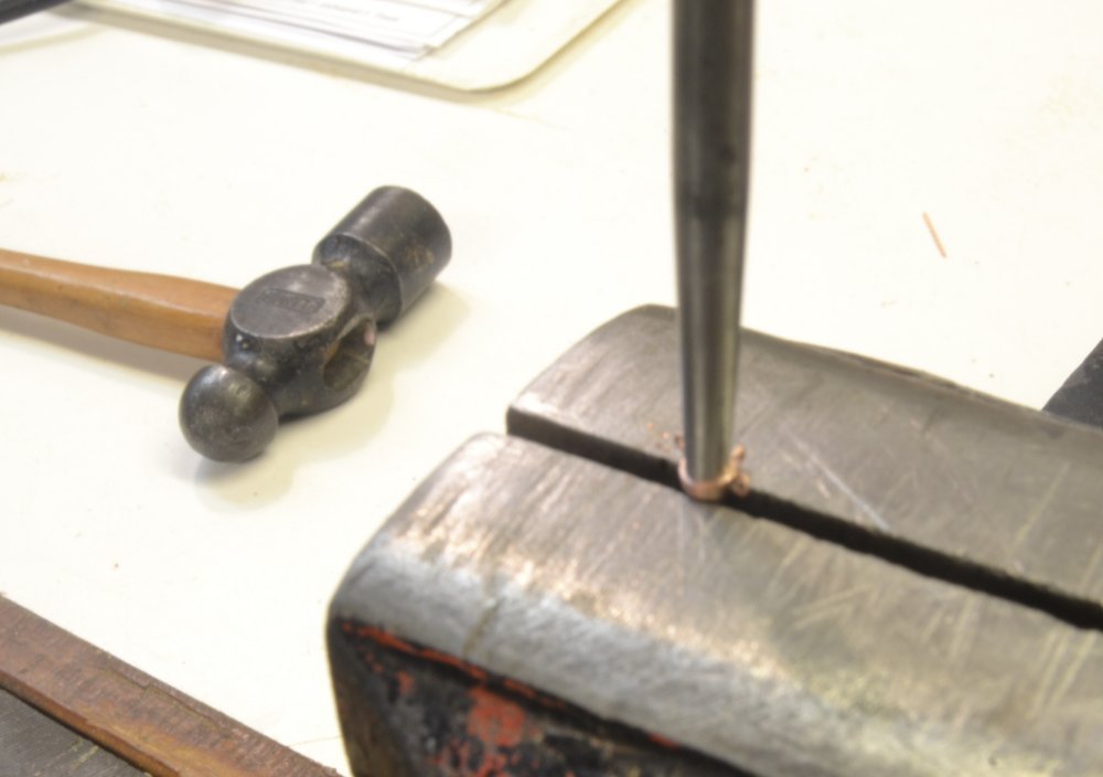
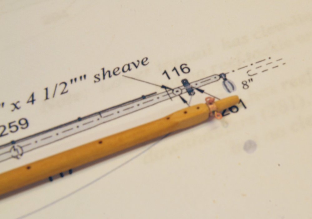
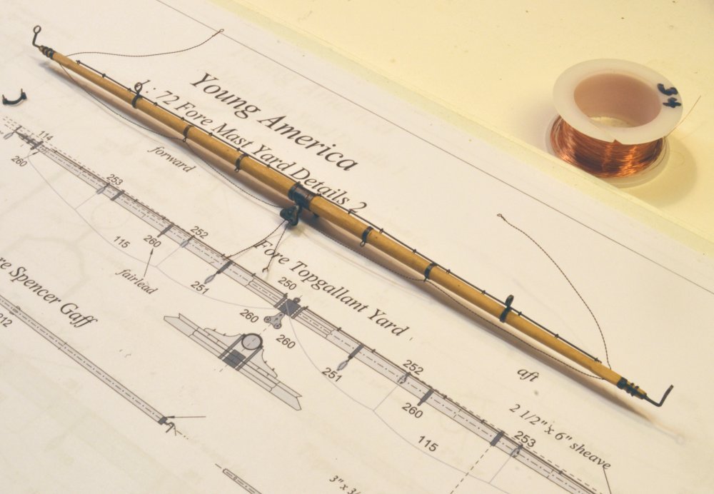
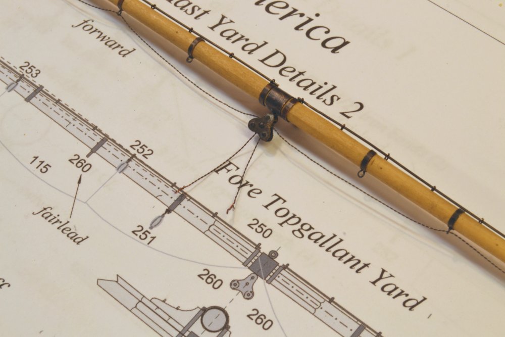
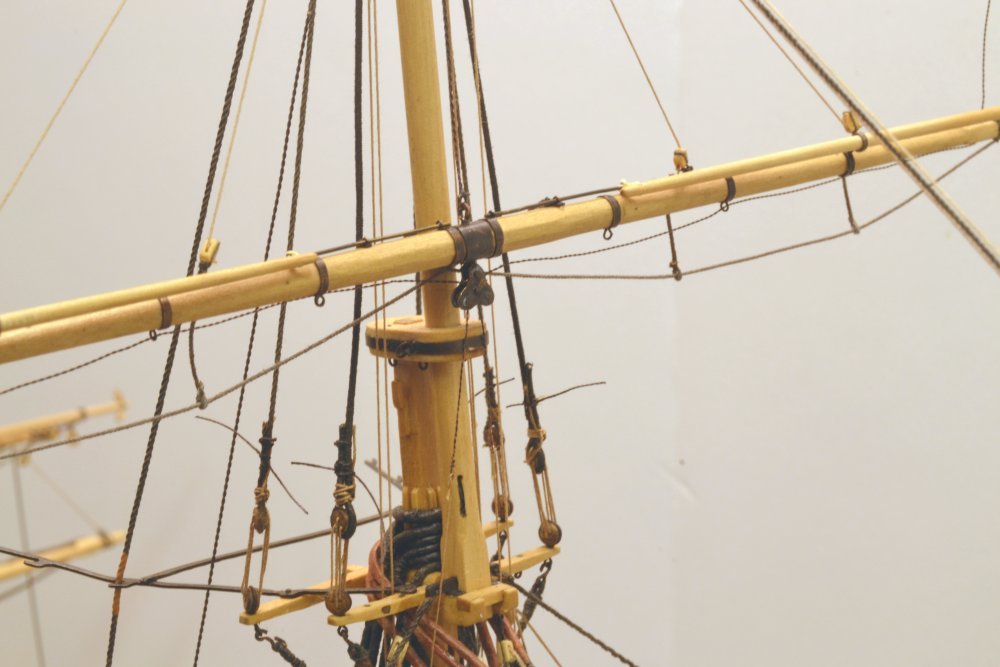
Young America - extreme clipper 1853 Part 307 – Small Yard Arm Bands Up until this point, the eyebolts in spar bands, including yardarm bands have been inserted and glued into holes drilled through the bands and into the wooden spar. This provides a strong eyebolt connection and anchors the band securely on the spar. On smaller yards the diameters at the ends are quite small, approaching 1/16" at 1:72. Drilling through the mounted band becomes more difficult at these sizes and drilled holes into the small spar weaken it. A different method was adopted for the fore royal yard and will be used on other smaller spars. Yet another method will be used on the very small skysail yards. In the first picture, eyebolt holes are being drilled into a length of copper tube with an ID slightly smaller than the fore royal yard arm. A slight flat was filed on the top surface of the tube and the drill bit projection kept short to reduce the tendency of the bit to "skate" on the round surface. When the necessary holes were drilled, twisted wire eyebolts were inserted and silver-soldered into the tube. Before soldering the eyebolts the OD of the tube was filed to reduce its thickness. In the next picture the eyebolt protrusions into the tube are being ground out using a small diamond grit bur. The end of this tube was then sawed off to produce the yard arm band. In the next picture a hardened steel mandrel and a wood block are being used to restore the round shape of the band and to begin its enlargement into a tight fit over the end of the spar. Final enlargement of the band was done as shown in the next picture by lightly tapping the band with a hammer using the vise jaws as an anvil – until the band was just large enough to be pressed on to the yard. The next picture shows the band fitted to the royal yardarm. The band was later removed for polishing before final installation. The other fabrication steps on this yard follow those described earlier so I will skip those steps. Note that the yard has been drilled for jackstay stanchions and for the skysail sheet sheaves, which have yet to be carved out. As with other yards, all copper ironwork was blackened on the yard as described in earlier posts. The last two pictures illustrate the replacement of the royal sheet chains on the topgallant yard. This change was mentioned in the last post. The first picture shows the new, slightly larger, royal sheet chains installed on the yard. This work was done in place, requiring removal of the old chain, re-threading of the sheet block, and re-connection of the two rope falls below the block. Ratlines on the topgallant shrouds – and other areas - are a work in progress. The last picture shows the new twisted wire chain at the port side of the yard. The twisted wire chain is stiff, so it stands up by itself and will need to be shaped later – along with all the foot ropes and stirrups. The pin in this picture anchors the chain in the sheave temporarily to allow the loops below the yard to be initially sized and shaped. Ed
- 3,618 replies
-
- 31
-
-
- young america
- clipper
- (and 1 more)
-
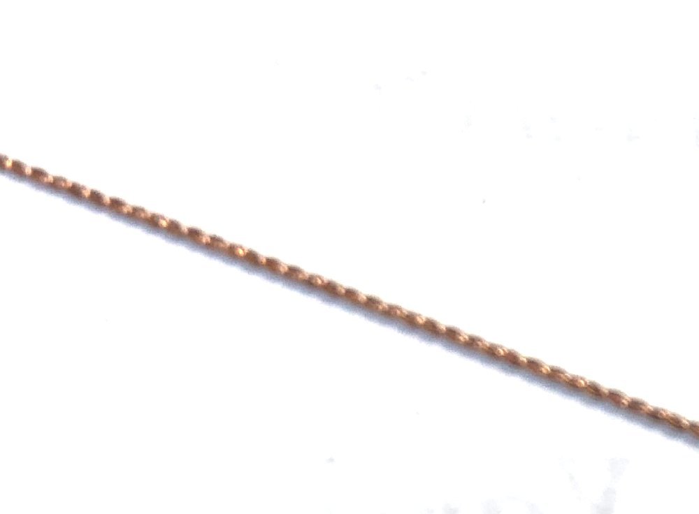
Wefalck, I was so intrigued by your idea that I immediately tried it with 36 gauge copper wire. Here is the result: A little out of focus using only my iPhone, but very credible - and with a little work.... worth some further exploration. Rob, it depends on the size of the sail. The topsails run to triple purchase tackles - at the deck for the lowers (or singles), at the top for the uppers, which have short travel. The topgallants run down to a simple whip from the deck, the royals and skys go directly to pins. Ed
- 3,618 replies
-
- 14
-
-
- young america
- clipper
- (and 1 more)
-
Young America - extreme clipper 1853 Part 306 – Fore Topgallant Yard 2 While the spanker rigging was going on, I also worked on rigging the fore topgallant yard. In the first picture most of the ironwork has been fitted as well as the fore royal sheet chains. At this scale these chains are well under the size of any available chain by a factor of more than 2. As with other small chains shown earlier, these were made by twisting a doubled loop of wire by approximately the correct number of turns for its length – assuming one turn per 2 links - an imprecise process for sure. The next picture shows a closer view of the chain and the sheet block under the center of the yard. After erecting the yard and completing its rigging, I decided to replace this chain with a slightly heavier version. I will show it in a later post. In the next picture, the yard's halyard - a somewhat larger twisted wire chain - has been passed through the topgallant mast sheave with a pin inserted to hold it in place. The chain may be seen just behind the mast in this picture. The position held by the temporary pin is set to suspend the yard just above the topmast cap. The chain halyard runs down behind the mast to a tackle shown in the next picture. The tackle is long enough to allow the yard to be hauled up to its full height. In the next picture, the yard with all its bench-installed rigging has been mounted on the mast. The halyard, slanting out due to its stiffness (see arrow), has not yet been connected at the sling band. Bunt and leech lines were routed down the mast before erecting the yard and may be seen draped from their double blocks above. The wire chain sheets are doing their own thing. Twisted wire behaves exactly opposite actual chain, which drapes beautifully in graceful curves. Wire chain has to be carefully shaped to do so. This will be done later after the loose ends are connected to the royal clue lines. In the next picture, the halyard chain has been connected to the sling band, the bunt and leech lines are rigged and the clew lines are connected to the chain sheets below. The royal sheet chains described above, were the first to be connected after the halyard, so that these could be used to pull down the yard. The next picture shows the halyard and its eyebolt as well as the two chain sheets hauled down below the sheet block. The thin chain sheets (later replaced) may be seen in front of the mast in this picture. Each leg is connected to a rope line that runs down to belay on the main rail, port and starboard. The bunt, leech, and clew lines run down inside the shrouds, through shroud fairleads and belay on those rails as well. The next picture shows these lines running through the top fairleads. All these fairlead holes are starting to fill up. The arrow in the picture points to the halyard chain. The main rail pins are also filling up as shown in the next picture. Finally, a view of the model in its present state. Ed
- 3,618 replies
-
- 39
-
-
- young america
- clipper
- (and 1 more)
-
Sweet. Thanks for answering my question. Ed
-
Looking really good, Maury - neat and clean. Those spacers never look great but they do the job - and of course you will have the pleasure of removing them later. The last picture shows wood in the CB well. Is that a temporary spacer? Maybe I missed something in an earlier post. If so, it seems like a very good idea. Ed
-
Bravo and congratulations, Micheal. Amazing work, start to finish. Ed
- 749 replies
-
- 5
-
-
- albertic
- ocean liner
- (and 2 more)
-
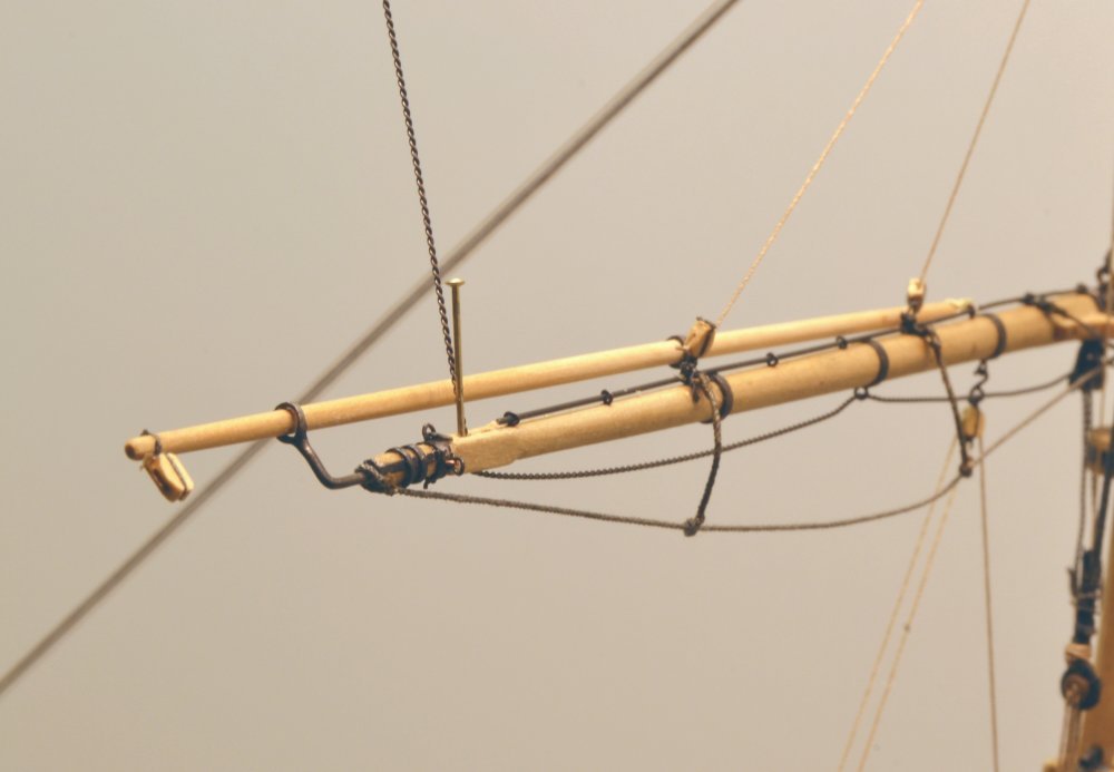
Young America - extreme clipper 1853 Part 305 – Spanker Gaff 2 (First a side note: While I very much appreciate some of the supportive comments following my last post, I deeply regret that we are having this dialogue at all. In the almost 6 years of regular posting on this site I have been very grateful for the comments, questions, suggestions, and yes, the constructive criticism that my work has received. In return I have done my best to answer all questions, explain detailed aspects of the work, appropriately adopt suggestions for improvement, and to improve the posts based on what followers seem to want. I truly hope that this will not be disrupted by any of my recent comments. I wish there were sufficient time to address every comment adequately, even those that require time consuming analysis, careful response, and yes, polite rebuttal. Unfortunately, time is limited. I only ask that my need to prioritize be acknowledged. Some basic clarification of the basis of my rigging work may help. There is no set of plans or definitive data describing the full rigging of Young America. The ship had a 30 year career, several different owners, and many different captains. The ship evolved from the extreme clipper concept of her early career to the more mundane plodding of her later years. Her career spanned a period of major changes in ships' rigs as chain, wire, and new iron fittings emerged. For these reasons I have never represented that my design is a replica of the actual ship or any other ship. The design is based on input from the best primary and secondary documented references available to me. Thanks.) The first picture shows the spanker gaff with all its rigging installed. A simple lashing between eyebolts on the throat was used to fasten the gaff to the spanker mast. In the picture the two lines slanted down to the deck in an inverted V are the vangs. These long pendants with tackles control the sweep of the gaff. A signal halyard is run through a block at the end of the gaff and belays on the iron rail. The next picture provides a better view of the peak halyard and other rigging to the gaff. The standing end of the peak halyard is fixed to the topmast crosstrees, runs down to a single block near the end of the boom, back through a double block at the cap, through another single block on the gaff, back through the cap block, then down to belay on the mast spider band. The head outhauler may be seen in the next picture. The standing end of the outhauler is stopped under the gaff at the gooseneck. It then runs under the gaff to the sheave at the end, back through a single block hooked under the port side of the cap, thence to a tackle hooked on the deck and belayed on the port pin rail. The tackle is long enough to allow the standing end of the line to be hauled out to the end of the gaff. The next picture shows the throat halyard tackle under the top. The throat halyard tackle that was used to raise the entire gaff is hooked under the port trestletree and to the throat of the gaff. The fall then runs down along the mast to be belayed on the spider band. The picture also shows the head outhauler stopped off in the block under the gaff throat band. The line stopped in this block is the head inhaul (or downhaul) used to take in the sail at the top. This line also runs down to a tackle on the deck aft of the throat tackle. The next picture shows the two tackles. The inhaul tackle is almost block-to-block since the inhaul is fully overhauled to the gaff throat – waiting for a sail. It will be nice to get rid of this unsightly masking tape but for now it is a lifesaver in keeping rope and other debris out of the decks below. Ed
- 3,618 replies
-
- 26
-
-
- young america
- clipper
- (and 1 more)
-
Wow. Fantastic clean woodwork - and that goes for your tools and benches as well. I'm in awe. Ed
-
Bob, you seem obsessed with the details of my spanker boom. Your opinions on these issues could no doubt be debated to exhaustion without adding much to our actual historical knowledge. I suggest you consult George Campbell, China Clippers, for an example of an underside boom cleat and Jeffers and Muprhy 1849 Nautical Routine for the configuration I used on the boom outhauler – admittedly one possible variation. Both are reliable sources – among others. You may find these useful before suggesting errors in my rigging decisions on this build log. That would certainly save me a lot of time in responding to these criticisms, and possibly avoid confusing others following the topic. I hope you will understand that for this latter reason I find it necessary to rebut at least some of your assertions and that this has become very time consuming – and frankly, not very productive.
- 3,618 replies
-
- 7
-
-
- young america
- clipper
- (and 1 more)