


EdT
-
Posts
2,214 -
Joined
-
Last visited
Content Type
Profiles
Forums
Gallery
Events
Everything posted by EdT
-
Thank you Piet and Tom, and thanks to the 10 who have "liked" the picture of my broken yard 😉😊. Tom, I have used three different methods to solve the problem of getting a round band to fit tightly over the octagon at the center of the yard. The first is just to push it over and flatten the sides when it is in place, but if very tight, the band may shave the neat corners off to some degree. Another method is to use small pliers to shape one end of the band then push it over and finish the shaping when it is in place. In both these methods the band may fit somewhat loosely, allowing it to move, but these central bands usually have top and bottom eyebolts that will keep the band in place. The best method is to use a tapered, octagonal mandrel - easily made from hardwood like the round one, using the methods for shaping spars. This is a good way to practice shaping regular octagons and once made will make the central banding problem much easier. I adopted this method late in the process - to my regret. I will look for a picture. Ed
- 3,618 replies
-
- 9
-

-
- young america
- clipper
- (and 1 more)
-
Thanks to everyone who has reacted or commented on the post. Let me address the questions: Dowmer, I use silver-soldering, exclusively, for the copper and brass work on the model. This is a high temperature process with flow temperatures in the 1200F to 1450F range, depending on the composition, primarily the silver content, of the solder. It is really brazing. I use a butane or propane torch - necessary for these temperatures. I use a low silver, phosphorus copper solder (1325F) for most of my work, mainly because it blackens consistently with the copper using liver of sulfur solution. The solder I use comes in a syringe of paste that includes solder and flux. Very small amounts may be dispensed and placed accurately. Here is a link to my supplier: https://contenti.com/jewelry-soldering-supplies/solder/phos-copper-solder-paste There are some other descriptions of the methods I have used in earlier posts and the books go into considerable detail on how to do this - at least how I do it. There are some rules of thumb: Joints must be in contact, silver-solder does not fill voids like soft solder. Heat control is important - small parts can be incinerated. Surfaces must be clean. Post pickling and buffing is necessary. There is more, of course. It is a process and there is a learning curve - but it is easily ascended with some practice Wefalck, the mizzen skysail yard is 5.5" at the center and 2.2" at the yard arm (~.075" and~.03" or ~2mm and ~1mm) at 1:72), so it is quite small. Fortunately it is not sheaved for sheets at the arms, but it is drilled (.024")for jackstay stanchions (28 gauge copper twisted eyes) and at the center for a sling eyebolt. The first one fractured as I was peening the underside of an outer stanchion to secure it in its through-hole in the yard. Risky. The second one broke as I was bending the strip for the central band around it. Again risky - and unnecessary. Photo below. I had no problem making these yards from Castello and I believe with care they would have survived and worked quite well. I expect to make the third, and hopefully final piece, from European boxwood, which is about 1/3 stronger than the tropical Castello substitute. I forsee no problem if I avoid abusing the piece. I am actually more concerned about the pole sections of the long, ie single stick, royal masts. Those are really vulnerable with no supporting rigging. Ed
- 3,618 replies
-
- 17
-
-
- young america
- clipper
- (and 1 more)
-
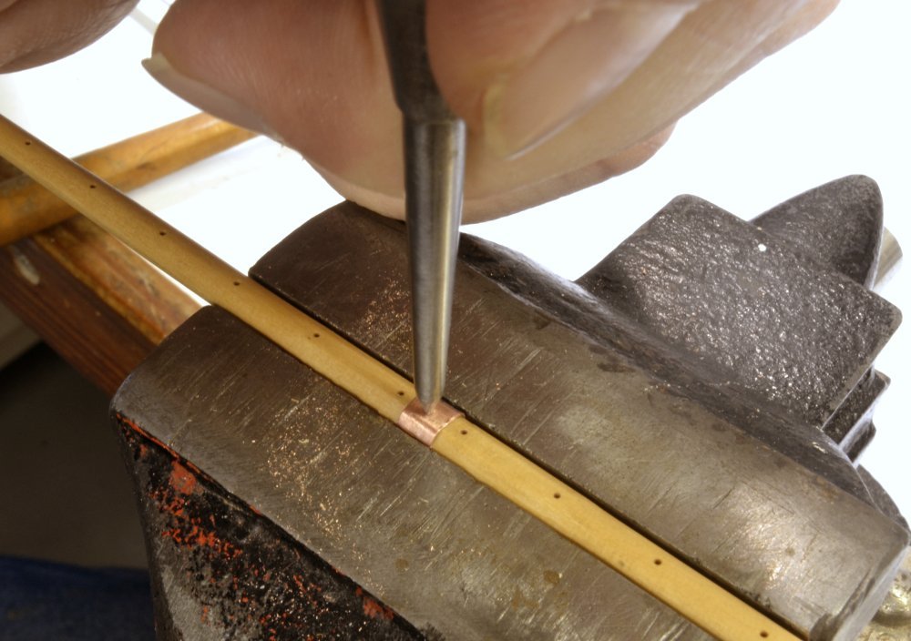
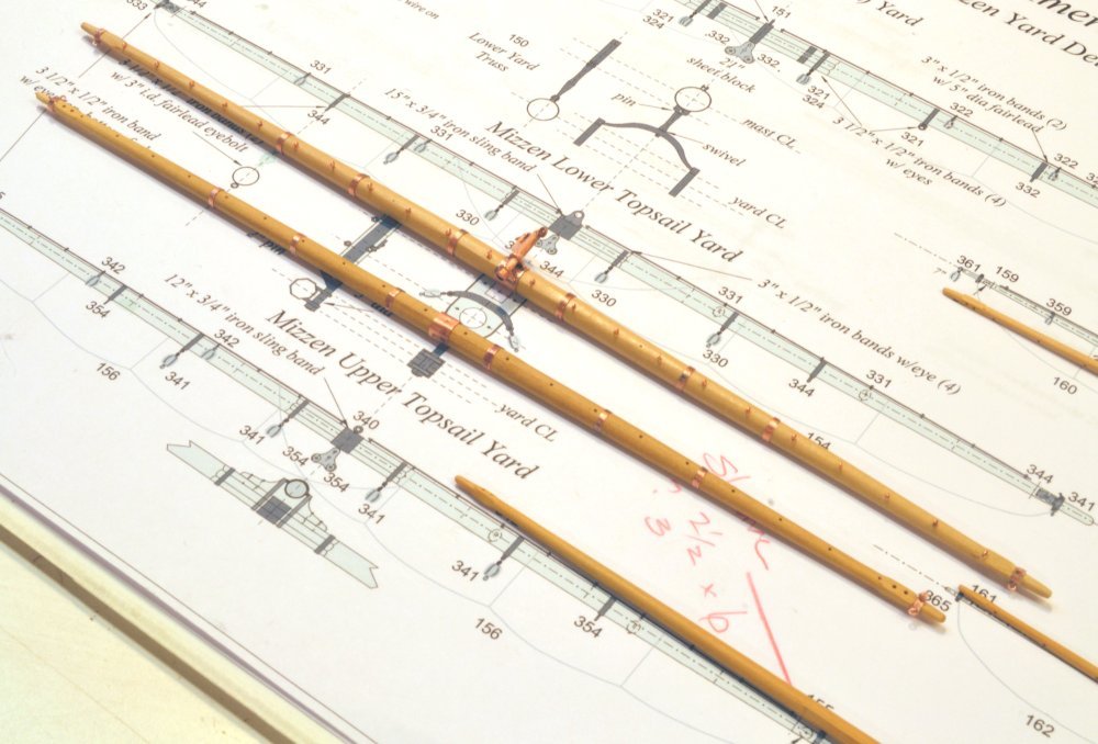
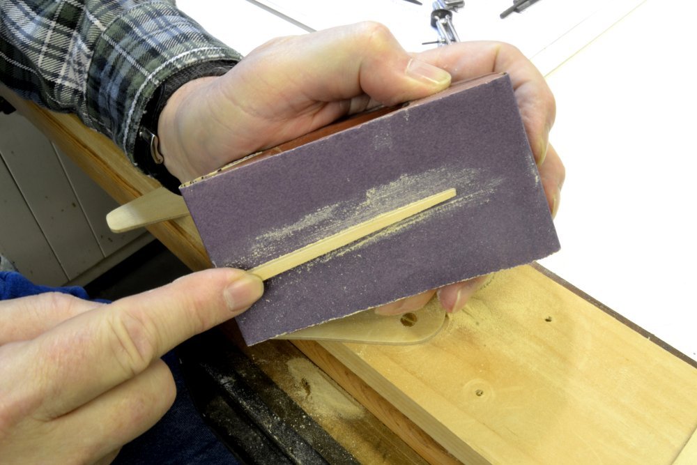
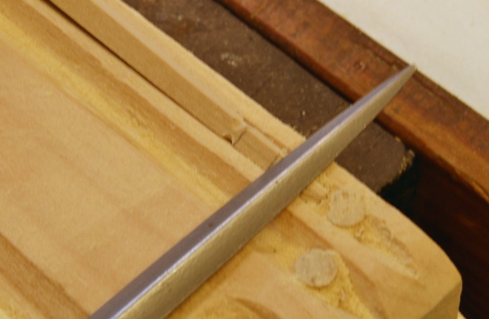
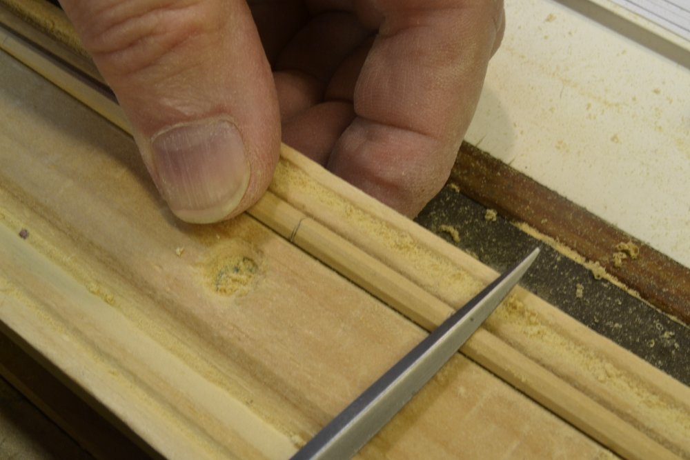
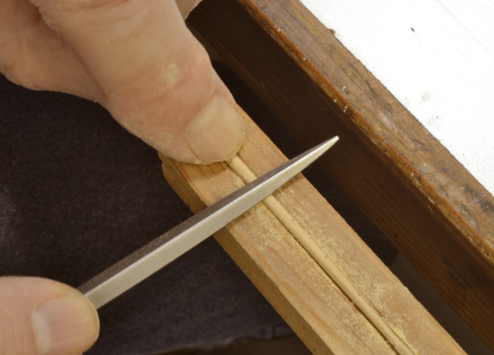
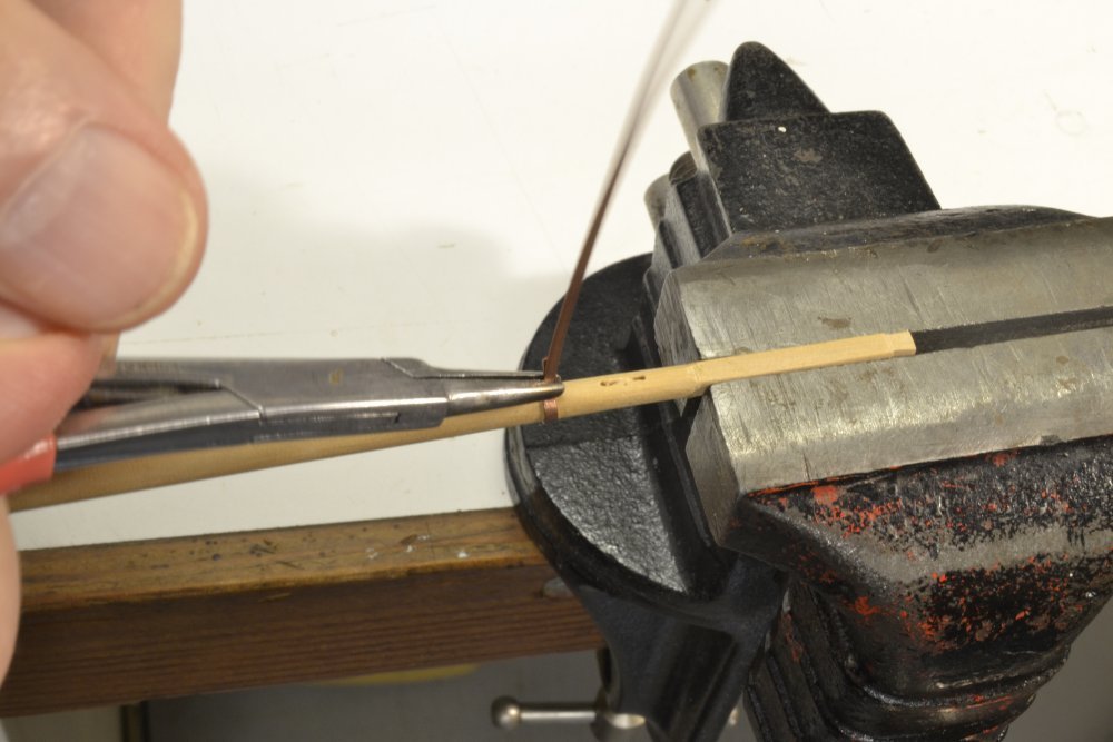
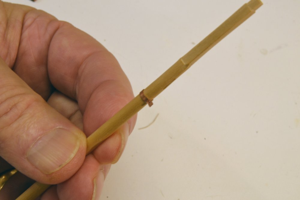
Young America - extreme clipper 1853 Part 314 – Iron Yard Bands Some of this may repeat similar descriptions of earlier work. Making the ironwork for the yards is the most time consuming part of their fabrication – and much of that work is very repetitive. There are many iron - that is copper - bands to be made and fit to the yards. Most of these are silver-soldered from .005" to .015" copper strip to approximate band thickness ranging from 3/8" to ¾" actual at 1:72 scale. The first picture shows strip for a ¾" thick sling band fit around its yard before soldering. The gap of around 1/32" is intentional, so the band may be stretched after soldering to a tight fit. No glue is used on these. Some are drilled for eyebolts and others for pins if extra strength is needed – for example on studdingsail boom irons. The next picture shows this ring after soldering. The bands has been pushed over the end of a hardwood, tapered mandrel to restore its round shape, stretch it to fit the yard, and for smooth-filing and buffing. Buffing is shown in the next picture. All this work is done on the mandrel to avoid marring or smudging the surface of the yard. Even with this precaution, fitting the bands causes some smudge, so the yards are given a "pre-finish" of wipe-on polyurethane for protection and to facilitate later cleaning. In the next picture the band has been fit to the center of the yard and is being center-punched for later drilling of the sling eyebolt hole. In the next picture the saddle for the parral has been glued to the yard over the band. The saddle will then be shaped and its reinforcing bands and copper bolts fitted where these are specified. Making these bands was described in an earlier post. The next picture shows a small band being enlarged using a steel tapered scriber. The enlargement is done on both sides of the band. The last picture shows a pair of larger yards – mizzen topsail yards – with their bands fitted. The jackstay stanchions have been fitted to the lower topsail yard. The yard arm bands with the eyebolts will be described in the next post. All these steps are proceeding concurrently on all the remaining yards – except for the tiny mizzen skysail yard – which is being replaced for the third time due to breakage and has therefore fallen behind in the work. Ed
- 3,618 replies
-
- 26
-
-
- young america
- clipper
- (and 1 more)
-
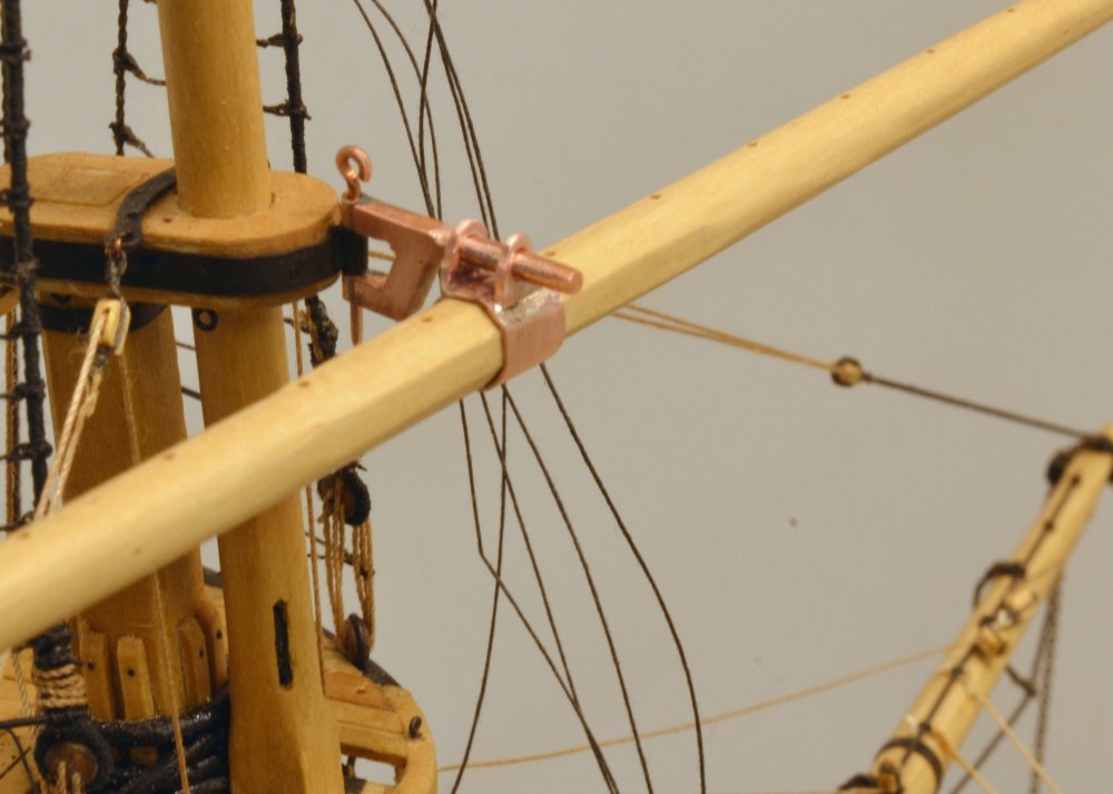
Thank you for these comments and likes. My reference for the adapted design of this fitting was - as with many other details - Harold Underhill's book, Masting and Rigging the Clipper Ship and Ocean Carrier. Given that the use this type of truss on Young America was an early application of what became the Howes patent design, there is much uncertainty of the actual configuration. The photos show the yard at the height of the cap, so this is probably a reasonable design. Ed
- 3,618 replies
-
- 4
-
-
- young america
- clipper
- (and 1 more)
-
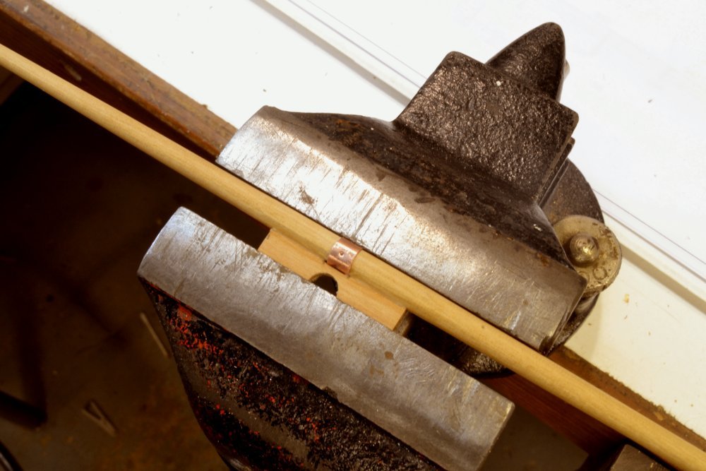
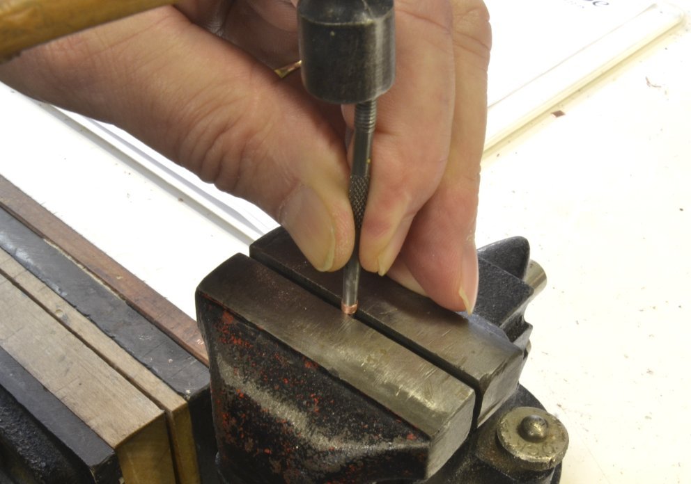
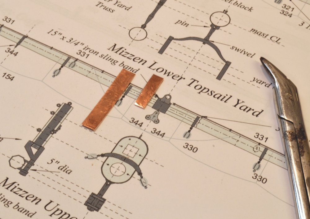
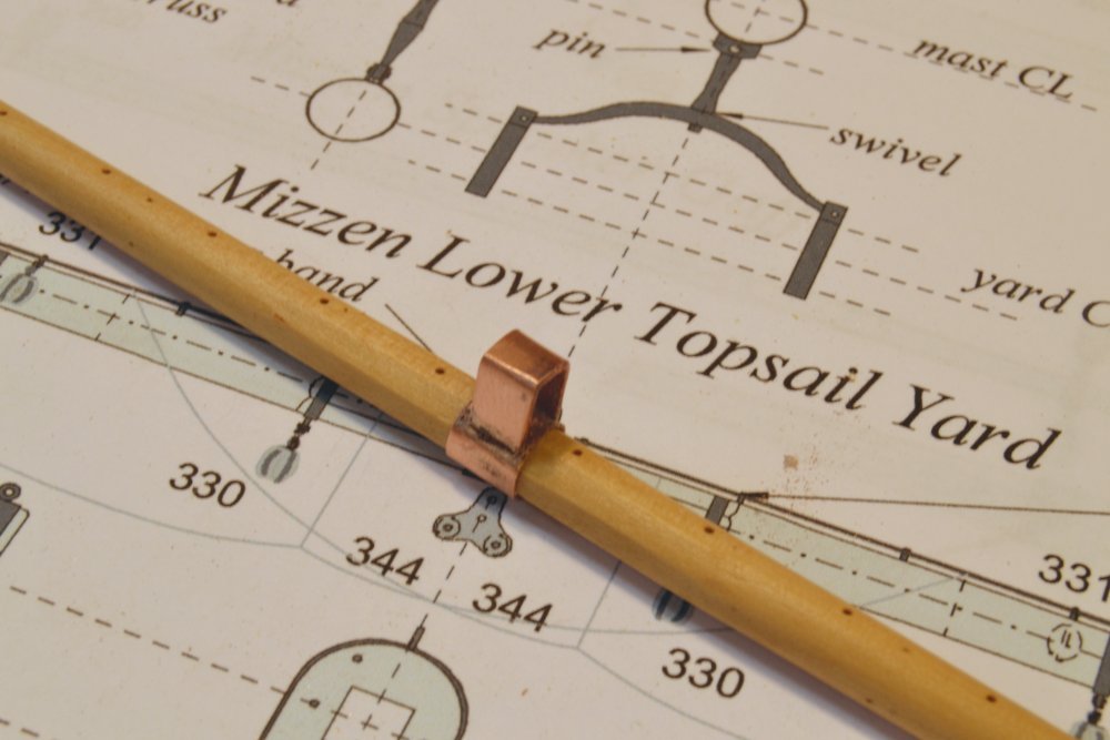
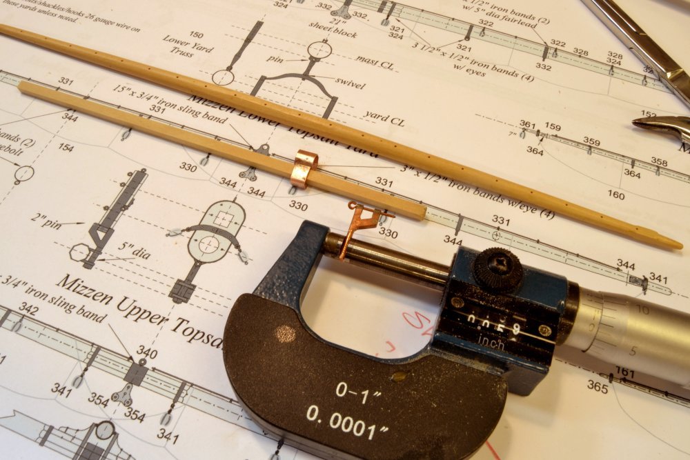
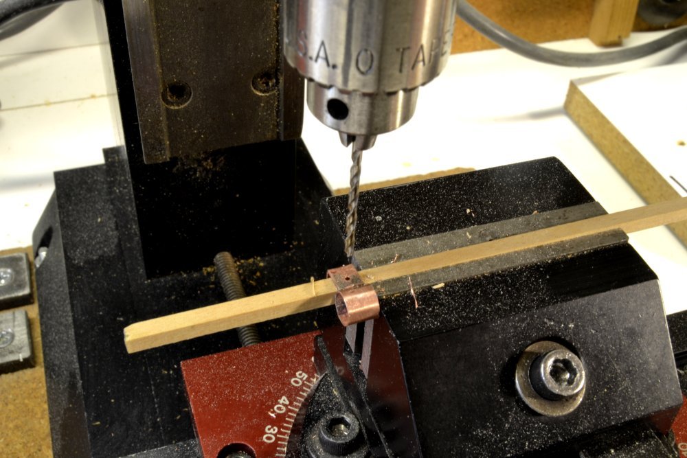
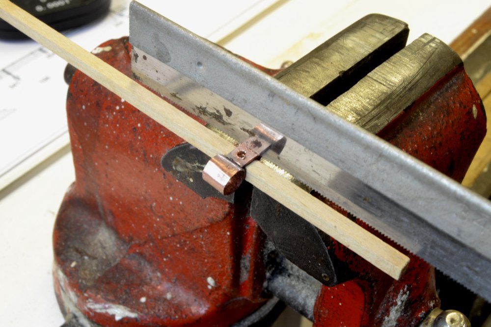
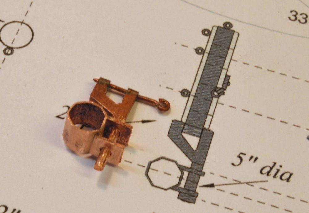
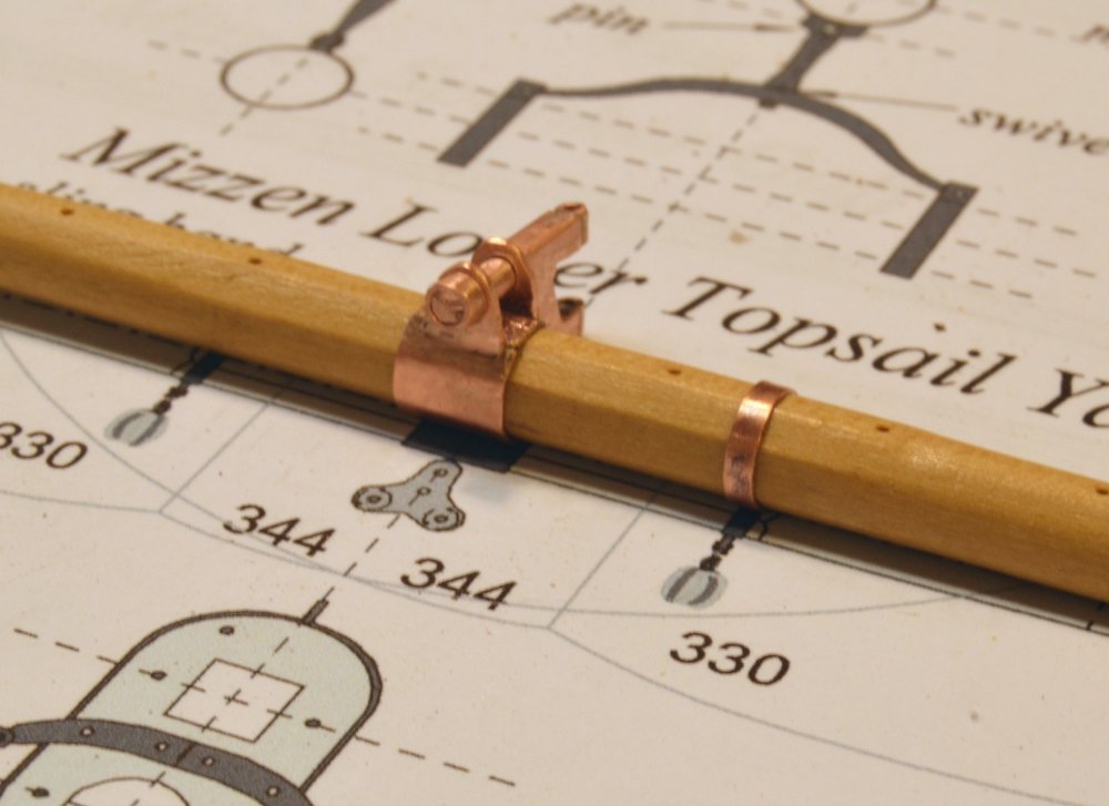
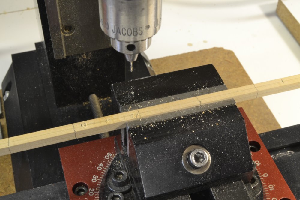
Young America - extreme clipper 1853 Part 313 – Mizzen Lower Topsail Truss I mentioned in the last post my plan to complete all the remaining spars at one go. That work has been progressing with minimal diversion to other tasks. Shaping all the remaining yards was described in the last post. That work passes quickly – unlike fitting of all the ironwork that is the most time-consuming part of the work on the yards. This post describes an interesting piece of that ironwork found on all three masts - the Howe bracket truss for the lower topsail yard - in this case the last of these, for the mizzen. The truss bracket pivots on a pin through a boss on the lower topmast cap. A horizontal bolt on this bracket engages ears fixed to the central yard band. The truss allows the yard to be rotated around the mast and "topped" to raise one side or the other. Since it is fixed to the mast cap, the yard cannot be raised or lowered, so the lower topsail is set at fixed size and not able to be reefed. The first picture shows copper plates cut for the parts of the sling band – and also the drawing detail for the truss assembly. The larger piece will become the ¾" thick band. The smaller, thicker piece will form the two ears for the bracket bolt. The band was first fitted around the yard, silver-soldered and stretched to fit tightly around the octagonal center of the yard. The method I use for making these copper bands was described in earlier posts and will probably be repeated in one of the next posts. A single U-shaped piece was formed, fit and soldered to the band as shown replaced on the yard in the next picture. Making the ears as a single piece facilitates drilling and alignment of the through-bolt holes. The next picture shows the assembly fitted to a wood strip that will support it for drilling. The diameter of the (5") bracket bolt is being measured in the picture for sizing of the drill bit. This bracket was made earlier with its fore and main counterparts. In the next picture the piece is held in the vise by the wood strip and a smaller pilot hole has been drilled through both sides of the U-bracket. The drill bit has been replaced with the larger final bit. After drilling, the top part of the U-bracket was sawed off with top section joining the two ears held in the vise. The wood strip steadies the work for this step and prevents bending of the ears. The next picture shows the rough truss assembly after removing the excess top piece. In the next picture the ears have been rounded and the truss test fit on the mast. The last step was to add a tight-fitting retaining ring to the end of the bolt and remove the excess length. The final assembly is shown below. After this piece is blackened after the rest of the "ironwork" is added to the yard, a drop of CA will keep the retaining ring from slipping off. The picture also shows the first of the other yard bands added. Ed
- 3,618 replies
-
- 36
-
-
- young america
- clipper
- (and 1 more)
-
I am arriving a bit late to this discussion, but I would like to toss out one thought that has not been mentioned. I do not possess any authoritative knowledge on this apart from what I have learned or deduced from rigging of my current model. Except for the lifts, there is no rigging that maintains a square yard in the horizontal position until its sail is set and sheeted, ignoring the lower yards and lower topsail yards on double topsail rigs, which are at permanently fixed heights and are supported at the ends by topping lifts and downhaulers, respectively. On models, upper yards may be held level by bunt and leech lines stopped in their yard blocks, but in practice these would have to be overhauled (loosened) for bending to the sail. The bare yard would thus be free to rotate, constrained only by its mast parral, and would do so when loaded unequally as men worked their way out onto it to bend sail. The standing lifts would maintain the level position of the bare yard when it was completely lowered. This would be essential for men working on the yard to bend sail. After the sail was set, the horizontal position of the raised yard would be maintained by the halyard at the top and the sheets at the lower ends of the sail as it was raised to its set height. When lowering the yard for reefing and furling , it could be maintained fairly stable/level by reef tackle in the first instance and by lowering down on the lifts for furling. This is deduction on my part. Considering that yards are generally bared in port, it would seem logical to have them down on their lifts after unbending and leave them there until sails are bent. Other reasons cited above - reduced upper mast loading/cg as well as reduced stress on the halyards - also seem appropriate. Ed
-
I have no plans beyond completing this model and the book.
-
Thank you all for the likes and comments - appreciated as always. Druxey, actually the monkey gaff may be used as a toothpick in a pinch - not that I would do that of course. Micheal. drilling the holes in the spars is a good example of letting the process develop before locking practices into mass production. After experiencing the issues of clamping and centering a round tapered spar for drilling the evenly spaced, centered jackstay eyebolt holes, drilling them as a first step was a clear improvement still available for the remaining two dozen. Kurt, thank you. We had a wonderful Thanksgiving even though we could not assemble the entire brood this year. We'll should be correcting that at Christmas. I have not thought about percentage complete - in fact I have some trouble remembering the year I started this - fall 2013 I believe. I will guess that the model is 95% complete and I am hoping to complete it early in the year. Daniel, I will see if I can get an illustrative photo, but I can tell you that most - not all - of the lines that run through the fairleads in the top run down behind the shrouds and through a shroud fairlead, then belay on the side rail. I try to pass them through the futtock shrouds and through the shrouds above the futtocks in a straight line to their destination. For those going through a shroud fairlead this is usually to one side or the other of the line's fairlead shroud. I normally wet about an inch of the line with thin CA, then straighten and sharpen it with scissors to help thread it through from top to bottom. Thanks again everyone. Ed
- 3,618 replies
-
- 7
-
-
- young america
- clipper
- (and 1 more)
-
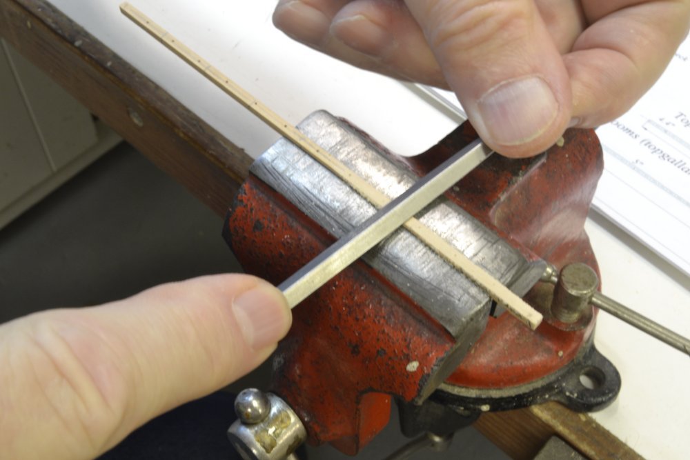
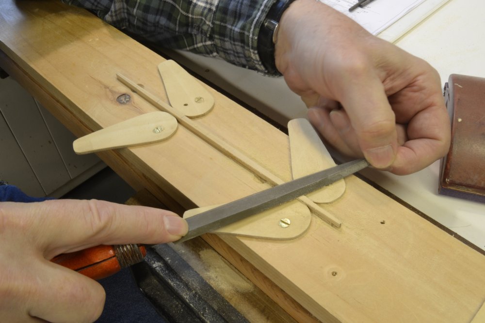
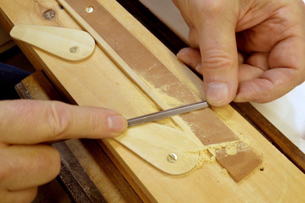
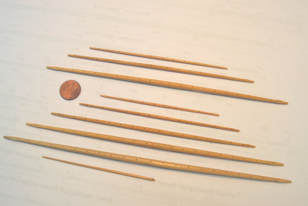
Young America - extreme clipper 1853 Part 312 – Spar Making Marathon Not a lot new in this post. Mostly work that has been shown before. I normally work sequentially, completing an item through all the steps, then installing and rigging it. This helps uncover any problems with the design or methods and allows corrections to be made before errors are duplicated. With the spar making process pretty well in hand and quite a few left to make, I decided to work these together to save time. Forming the remaining upper yards – three for the main and five for the mizzen - is described in this post. The blanks for all the spars had been cut and sized earlier – the so-called "first trims" – squares of the maximum spar diameter cut to length. After marking the centerlines and quarters, centerline holes for the jackstays and sheet sheaves were drilled as shown in the first picture for one of the larger yards. After centering and determining the spacing for the jackstay stanchions the holes were drilled using the mill hand wheel to locate each .024" hole. Where yards had internal sheaves for sheets, these were also drilled to the required size. After this drilling, each spar was shaped and finished before proceeding to the next. Some of these steps are described below. I believe all have been described in earlier posts. This next picture shows the first tapering steps on one of the spars, with the work held in a vise in this case. The vise was used in this way for the first tapering on smaller spars, instead of the cam fixture shown below. Once two opposite faces were shaped to form the second trim, the larger tapered spars were mounted as shown below to form the tapers on the two remaining sides. To adapt this fixture to smaller work, it was modified by substituting a fixed straight fence as shown in the next picture. This eliminated flexing of the small spars between the cams. These spars are also small enough to deflect at the ends to the straight line of the fence. Final shaping, and most of the shaping on the smallest spars, was done using a sanding block with 220-grit paper as shown in the next picture. This works well for light wood removal and also for maintaining fair curves along the spar. With the four sides tapered, the octagonal shape was first applied at the ends, around the square sections. I made rounded transitions on the insides of these sections, but squared off on the outer side to receive the yard arm bands. The octagonal shape was then filed on each spar inside the square end sections. This process was illustrated in earlier posts. In the next picture, the central octagonal area of one of the spars has been marked and the rounding has begun starting with file strokes that begin at the mark and remove the eight corners along the spar. All the square yards are left octagonal at the center. Finally, the remaining corners are filed off to form the rounds. A smaller grooved holder is shown above, but much of this final rounding is hand held. The corners are first removed using the file, then with a sanding stick. Throughout all the above work, calipers are used to check both diameters at the quarters and the rounded shape. The last picture shows the set of finished spars – the last significant wood work on the model. The top three spars in the picture are the main topgallant, royal, and skysail yards. The next five are the mizzen from the lower topsail up to the skysail. The very small spar at the bottom of the picture is the mizzen monkey gaff. All have been finished with one light coat of wipe-on poly to help keep them clean as the ironwork is added – the next work to be done. Ed
- 3,618 replies
-
- 33
-
-
- young america
- clipper
- (and 1 more)
-
Yes, I think I was having what we call a "senior moment." Your explanation makes sense. The mechanics of this are complex. Ed
- 3,618 replies
-
- 2
-
-
- young america
- clipper
- (and 1 more)
-
Last night at about 4am I came to the realization that my analysis in the first paragraph of the last post is complete nonsense, since rope contracts when wet and not the opposite, which my explanation tries to explain. So, apologies to all for this faulty logic, but especially to Wefalck whose rationale makes much more sense and is consistent with the actual observed behavior of the rope. Because my comments were backwards, I have edited out that paragraph from the post - to keep from confusing others and to avoid further embarrassment. Sorry for this. Ed
- 3,618 replies
-
- 4
-
-
- young america
- clipper
- (and 1 more)
-
Lou, thank you for you comment. It has been some time since I have seen your presence on MSW - was it Cutty Sark posts?. My camera does indeed have a white balance function that I keep set to auto. The color correction issue in my shop is due to a variety of lighting types in different areas - florescent overall, incandescent or LED spot lighting, and sometimes sunlight. These differences effect the photos depending on the location of the shot. So, to avoid constant resetting of the camera, I use auto white balance, then post-correct. I also occasionally use other cameras as well as the iPhone and these produce different hues. I post-correct to make them more consistent and to bring them closer to my perception by eye - using auto color balance, lightness/contrast, and sometimes RGB adjust. I do this for each post when I crop and shrink the images. Monochrome photos for the books also require post-work - usually lightness and contrast. I will try the white balance method you suggest. Ed
- 3,618 replies
-
- 1
-
-
- young america
- clipper
- (and 1 more)
-
Yes, an interesting problem, Druxey – and one that merits some consideration since it has noticeable effects on the model – some potentially negative, some perhaps helpful. I would be interested in hearing more about your hardening process, but I assume it is as described in Swan IV. After making rope, I stretch and hold the line until it stabilizes at the stretched length – usually a 5 to 10% increase in length. I then dye it (aqueous) and hang it to dry, then pass it through a flame to remove fuzz. Lately I have been adding a "sizing" of diluted PVA to reduce later fuzzing – passing the line through the solution, re-drying it and again flaming it. I am still experimenting with this sizing step. I am doing this to combat fuzzing of cotton lines during rigging. (Illogical paragraph suggesting rope increases in length due to moisture removed to avoid confusion. Rope actually shrinks when wet.) Treating the rope to reduce moisture absorption should reduce the effects of moisture on length. I have soaked the larger stays with a solution of wax after installation, but do not know if this has helped. The waxed lines did sag. I also do not know what effect the glue treatment will have. Both these treatments should reduce the moisture effect - but to what degree?
- 3,618 replies
-
- 4
-
-
- young america
- clipper
- (and 1 more)
-
It is probably better to have taut lines relax when humidity drops rather than having taut lines tighten further when humidity rises. This could easily distort masts and spars. One solution would be to pre-dampen lines that are run during very dry conditions. I found that my lines that had gone slack with the drop in humidity tightened right up again when dampened. Of course, this applies mainly to long lines. Ed
- 3,618 replies
-
- 2
-
-
- young america
- clipper
- (and 1 more)
-
Jan, I will try try to answer this by saying that various methods were used. Normally the tension would be applied at the lower end of the stay after fitting the collar over the masthead at the upper end - at least that is my interpretation. The lower end could be a thimble attached with a lashing that would allow for some adjustment, or the rope might pass through a bullseye or even an eyebolt if the rope was small enough. The doubled forestay was looped under the bowsprit and each leg seized to the other above on the opposite side. All these lower ends could then be hauled tight and secured with seizings. The final tension on the stay would be supplied by tightening the backstays and initially the shrouds- usually the backstays. These were fitted with deadeyes and lanyards for this purpose and were hauled up after securing the forward stays - I believe. This is the general approach I am following, using seizings or simulated wrapped splices at the top end collar. Hope this helps.
- 3,618 replies
-
- 4
-
-
- young america
- clipper
- (and 1 more)
-
Thank you, Greg and Micheal and others for the likes. The catenary curve on models is easily disrupted by irregularities in the small rope as well as the light weight. However, I believe if the rope is fairly uniform and well stretched, then installed taut under humid conditions, the relaxation when it dehydrates will cause it to droop in a smooth curve - at least that is what I am seeing in the slack lines I mentioned. The smaller, lower yard bowlines are nicely curved as well. Some of the very small lines not so much. Thanks again, Micheal for your comments on the small scale. It has its advantages and disadvantages. The latter are felt in the close up photos and while some of the flaws revealed in pictures like the one of the fore top may be correctable, some are just too small too fix - at least for me. The excess ends on the seizings and lashings being the most problematical. Thanks for the comment on the photo, Greg - taken with my iPhone. Most of the the photos for the posts and the books were taken with a Nikon D3100 SLR with aperture priority - stopped down to around F22 to maximize depth of field - no question of handheld for these because of the slow shutter speed. The iPhone pics are very crisp at the focal point in closeup situations but the depth of field is very shallow - sometimes a good thing, but often not. The phone has the virtue of small size so it can be inserted into the model. I have been experimenting with it for photos like the one above and also for deck-level photos. Unfortunately these photos often reveal even more glitches with the work. thanks again for the comments. Ed
- 3,618 replies
-
- 6
-
-
- young america
- clipper
- (and 1 more)
-
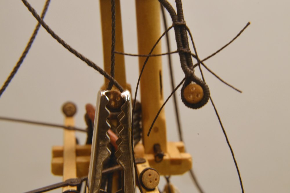
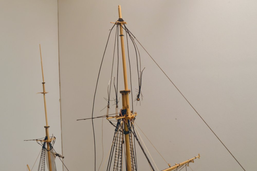
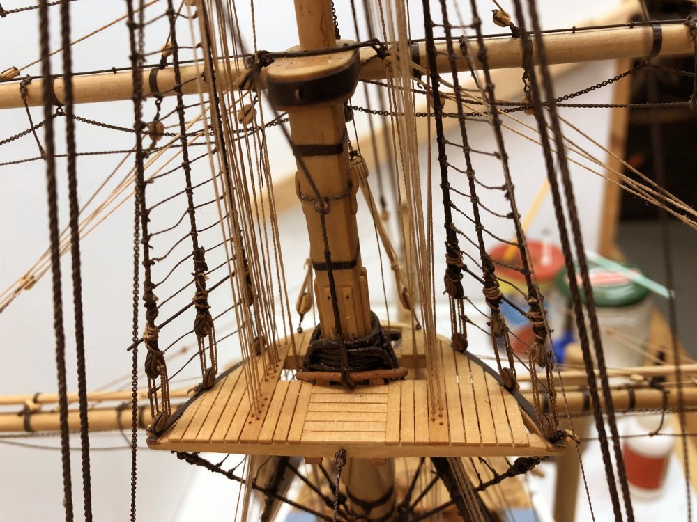
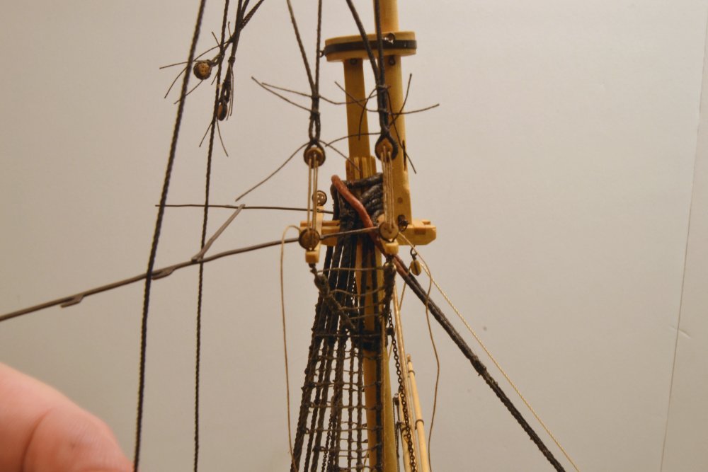
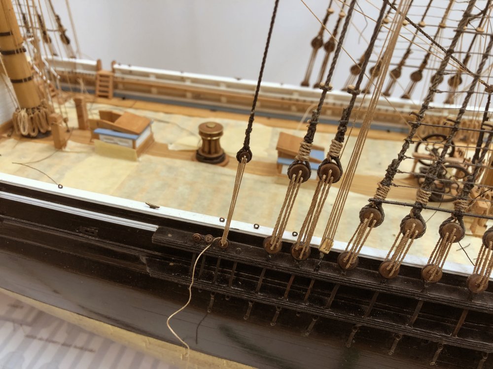
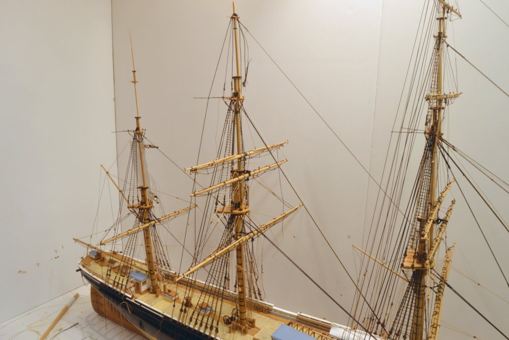
Young America - extreme clipper 1853 Part 311 – Main Topgallant Mast It has been an interesting week in the shop. Temperatures in our area dropped below freezing this week, with the usual drop in humidity, causing the long stays on the model to sag somewhat from their taut condition when installed during the warmer, more humid months. The sag on these is not too displeasing and actually mimics the sag in the photos of the ship. I measured this by magnifying the images and drawing straight CAD lines to compare. This could be corrected by hauling up on the backstay lanyards but for now I am not doing this. The topic in this part is the main topgallant mast. This and its crosstrees were made earlier. Before erecting the mast, the iron band for the royal futtock shrouds needed to be installed. This is placed at the smallest mast diameter, just under the octagonal hounds that spread outward to support the crosstrees. For this reason a soldered band cannot be used. The first pictures show the way I made this band. The copper strip was first crimped around the mast in a way that formed two tabs on the aft side. One of these was cut shorter than the other so the longer end could be bent and pressed over the first to form the flange-like tab shown in the next picture. In the picture this has been drilled for the four futtock shroud eyebolts. It was then blackened and the eyebolts glued in with CA. The crosstrees were then fitted and the mast erected. The next picture shows the foot of the installed mast and the turning-in of the two tg shrouds on the starboard side. The mast fid with its shackle may be seen in the picture. The forward, served shroud has its deadeye turned in with three seizings. The second shroud, to the left, is ready for its throat seizing. The deadeye is held in an alligator clamp for this. The next picture shows the tg mast with lanyards threaded on two of the shrouds and other lines hanging loose. The loose ends of the shrouds and seizings will be trimmed off when the glue coating dries. The forward stay has been run, but the upper collar seizing remains untied at this stage. The lower end of the stay is shown in the next picture. The stay is served at this end and passes through a bullseye strapped to the fore lower masthead. It is then seized to an eyebolt through the center crosstree. This picture also shows the fully loaded fairlead planks with just a few spare, unused holes. The next picture shows a closer view of the shrouds as the tg backstay is being prepared. The next picture shows the deadeye and lanyard connection of the backstay to the channel. The stay and shrouds are threaded but will not be hauled tight until their port side counterparts and the forward stay are rigged. The next picture shows the state of the model before rigging the port side lines. The sag of the topmast and lower mast stays may be apparent in this picture. While it is not very pronounced and perhaps realistic, it is counter to the desire for a tight, rigid structure – I guess. Interspersed with the above work, the dreary and eye-straining making and tying of ratlines continues. I estimate there are around 650 of these on the model. Ed
- 3,618 replies
-
- 32
-
-
- young america
- clipper
- (and 1 more)
-
I look forward to seeing your results with the guns, Mark. One additional thought I had about casting: I don't know if you are dusting the mold with talc before pouring, but that will reduce surface tension in the mold and improve the finish of the castings. Just dust it on the mold with a brush. Some people use baby powder, but here is a link to purpose-made stuff: https://contenti.com/jewelry-casting-supplies/mold-making-supplies/mold-release/talc-powder Ed
-
Hi Mark, I evidently missed your post on the tools question. Attached is a pdf from Sherline on tool grinding. If you have Sherline or other HSS tool bits, this should be helpful. Hardening these should not be necessary and is not mentioned in the instructions. If your are using mild steel for the tools or unhardened tool steel you may use files to shape the cutters. Hardening the shaped area after shaping may then be done easily using a torch, pliers and a soup can half full of olive or canola oil. See Naiad Vol I for more detail on the heat treating. HSS or hardened bits may be shaped them by grinding using diamond grit burs or files, or you may anneal the cutter by heating to cherry red then allowing to air cool. Pass a file over the blank to determine if it soft or if you get the distinctive "ring" from a hardened tool. If you have YA Vol II, there is some information on the CD about making lathe tools that may be helpful. If you do not have this, pm me. Ed grinding.pdf
-
Paul, I believe this block on the channel would be for a running breast backstay fall or for the fall of a shifting backstay. These are described in James Lees, The Masting and Rigging of English Ships of War 1625-1860 (p.55). "Breast Backstays Runn." are also listed for topmasts in Steel's Elements of Mastmaking, etc. (p. 239) with falls and blocks. In both references tackle blocks are double and single, however, not triple (?). In McKay's Victory AOS, the rigging list includes stays of this type with tackles for top and topgallant masts. The topmast tackles are shown on his standing rigging elevation drawings, but those for the tg mast are listed but not shown. Longridhge also describes these and shows the channel blocks in his drawings in Anatomy of Nelson's Ships. I installed these on Victory's fore and main topmasts and that triggered my recollection. Not a definitive answer but may help you track them down. Ed.
-
I would use 1 to 1 Rapid. It held up for me with many pours and deeply undercut patterns.
-
More on casting. The mold shown in you photos would be improved with a vent out of the bottom end - at the pommel. This will cause the air to be forced out by that route and will allow the metal to flow through the mold taking some gas with it. I would support Druxey's recommendation of lead-free pewter. I used various blends of metals, from linotype metal to Cerrobend - but most of those cantain lead and I would not use those today - even though my painted figures have - some pure lead - have help up for up to 40 years under their acrylic paint. Allan, I would love to hear and see more on your one-piece mold process. Results look great. Ed
-
Gaetan, I agree that your method is better for the reason you state - centering of the barrel bore - very difficult after turning the barrel. Your method also allows all the heavy turning to be done with the piece held at the large end - until the final turning of the pommel and parting off. I would definitely recommend your method. My Victory guns were the first turning project on my new Unimat ( in 1978). I would probably cast these today. Casting the guns in say, pewter, in an RTV mold would be easiest and the quality should be equal to turning. The biggest problem I have had with casting in RTV - over 5000 military figures and artillery - is degassing the mold - especially in areas like the gun bores - I eventually resorted to a vacuum chamber and pump to remove bubbles from the molds before curing and a centrifugal caster to de-gas the metal - not something you would want to do for 100 or so casts - but for simple gun barrels careful brushing of the rubber over the pattern should suffice - plus of course, venting - if you go this route. Turning every gun is not the best route - but with all our equipment we can't resist wanting to do it that way. Have fun. Ed
-
Looking sweet, Maury. Getting those deck clamps in really ties it all together - and soon no more spacers. Ed
-
Mark, I like the idea of decking under the guns - this will also help with hanging the tackles and breeching realistically. I turned the 100+ guns on my Victory using the Unimate with the headstock rotated slightly for the tapers. I did not have a duplicator - and still do not - but relied on a set of adjustment increments to duplicate each barrel profile with shaped cutters for each end of the barrel. I did each step on all the barrels of one size gun with the business end of the barrel chucked and without a tailstock center - starting with the shaped pommel, then the tapers, then the barrel rings, etc. Drilled the barrels after cutting off the stub. A very manual approach, but worked well. Care is needed to center the barrel bores. Here's a description in one of the Victory posts. ps. I see Gaetan used much the same method I did, but from the other end - probably better that way. But either way the work goes quickly once the process is set. Ed