
HOLIDAY DONATION DRIVE - SUPPORT MSW - DO YOUR PART TO KEEP THIS GREAT FORUM GOING! (89 donations so far out of 49,000 members - C'mon guys!)
×


EdT
-
Posts
2,214 -
Joined
-
Last visited
Content Type
Profiles
Forums
Gallery
Events
Everything posted by EdT
-
Amazing, Micheal amazing. My hat is off. .
-
Perfection - or as near as possible.
-
Or up to the trucks? I assume they shinnied up the poles, which ranged from 4" to 6" in diameter. Seems crazy, but these upper topmen had to be like monkeys. I have seen ironworkers do things I would never contemplate. Also, I have not seen ratlines on the double royal shrouds. They must have gone up those hand-over-hand. There was not much need to get on the skysail yards, since these were raised and lowered as a unit with the sail bent, using the halyard. The braces could be fixed to the ends at a lower level. These are my assumptions based on what I have read and on drawings/photos. Ed
- 3,618 replies
-
- 3
-

-
- young america
- clipper
- (and 1 more)
-
Rob, tension on standing rigging is a constant issue, especially with changes in humidity and the sizes of the model lines. I have had many of the deadeye lanyards on and off for adjustment a number of times and have actually replaced some stays. This is particularly difficult where running rigging is attached at an angle, as is the case on most stays and many shrouds. Deflection at these points was probably evident on real ships as well, given the sagging of standing rigging seen in some pictures and the strain some running rigging would induce in high winds. Eighteen or so lines hauled through fairleads on a gang of shrouds would also exert some inward force. Although Jacobs ladders are shown to the top of the royal section on the photos in which the ship has pole masts, they do not extend up to the sky masthead. The stepped mast configuration I am using has shrouds but no ratlines to the royal mast head. In both cases there is nothing to the sky masthead, so at present I do not intend to add these. Ed
- 3,618 replies
-
- 3
-
-
- young america
- clipper
- (and 1 more)
-
Thank you, Micheal. I do harden the ends of line with thin CA and also snip the end to an angled point, but the coloring idea is brilliant. Thanks. Actually, most fouling is detected once the line has been pulled taut, but the color sure would help find the ends under the tops and crosstrees. As to steady hands, I could only wish. Worse with each passing year. Ed
- 3,618 replies
-
- 6
-
-
- young america
- clipper
- (and 1 more)
-
HMS VICTORY 1765 by albert - 1/48
EdT replied to albert's topic in - Build logs for subjects built 1751 - 1800
A huge project, Albert. I am sure it will be epic. I look forward to your work on this. Ed -
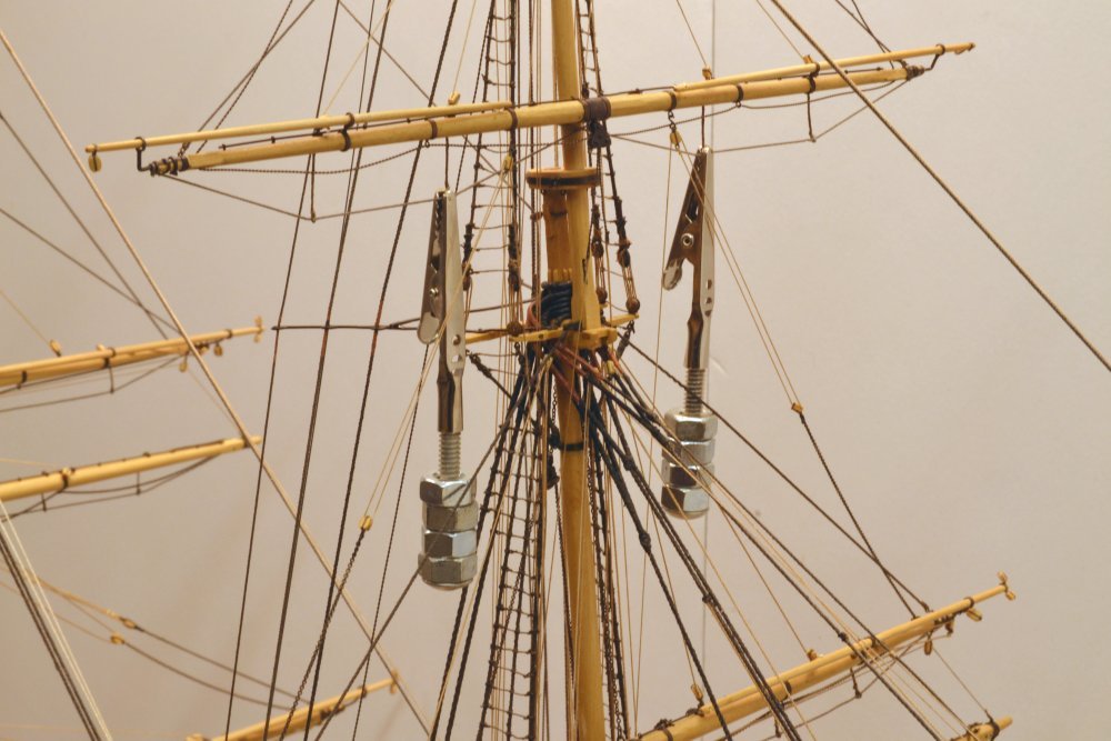
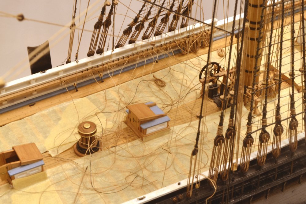
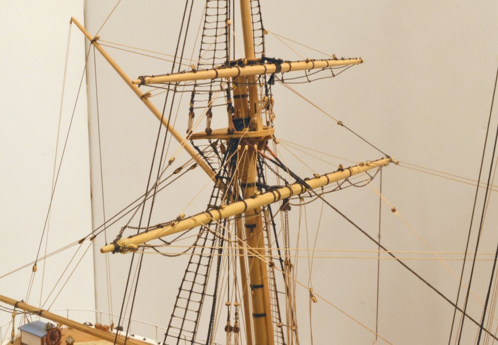
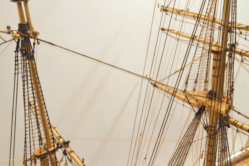
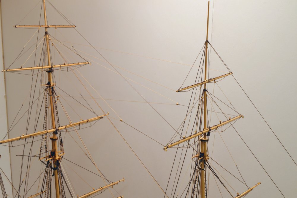
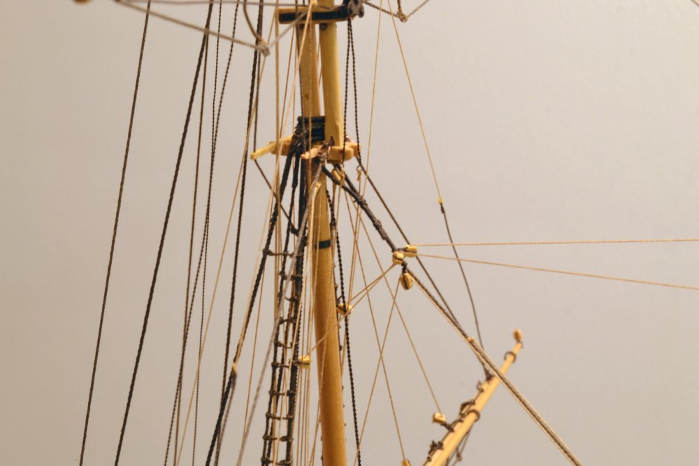
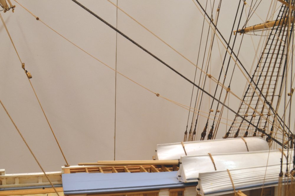
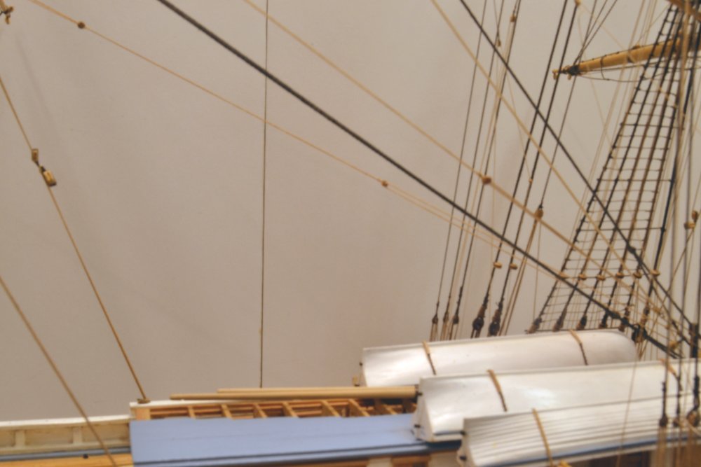
Young America - extreme clipper 1853 Part 318 – Running Rigging Continued It's been at least a few weeks since the last post. Apologies. Work is proceeding, but a lot is repetitive. The first picture shows some straightening of footrope stirrups, in this case on one of the completed foremast yards. The stirrups are straightened by hanging weighted clamps, then soaked with dilute dark glue. The next picture shows the tangle of running rigging lines on the deck aft of the main mast. These excess lengths are being left until all the lines are adjusted for tension. This makes for a mess and some tangles among lines, but this is preferred to rerunning an entire line if it has been cut short and later removal from the pin is required. The next picture shows the lower topsail yard on the mizzen that has just been set. The buntlines and upper topsail sheet tackles have been rigged. The tackles are hooked to the rim of the top and tied off to themselves. The chains for these run through the sheet block, under the yard, and through the cheek blocks with the short lengths above the yard tied off to the jackstays. The sheet chains for the lower topsail yard are as yet unconnected to the clewlines. The port chain is hanging vertically while the one on this side is draped on the lower yard. These will be the next lines rigged. The next picture shows the mizzen topmast stay and the running rigging for its staysail. There were three staysails on each mast. The halyard is tied off to the stay at the top, then run down along the stay to a block, then back to another block at the top of the stay, then directly down to the deck. At the lower end, the downhauler is tied to the lower block, then runs through a lead block and down behind the top to belay on the foremast fife rail just forward of the cabin – the most difficult belaying point to reach at this stage on the model. Work has finally begun on the yard braces, the last major rigging task. The braces for the fore royal and skysail have been run and are shown in the next picture. Braces are left until last to permit access. Outboard lines are a major obstacle. For some weeks now I have been regretting the early running of lower yard bowlines and crojack braces. The black pendants on the royal braces makes those more visible, as opposed to the small, light-colored lines that attach directly to the ends of the skysail yard. The next picture shows the running parts of the royal braces at the top of the topgallant stay. The lines run from the yard pendant blocks, through the two blocks on the stay, through single blocks lashed to the royal shrouds, then down to the deck. The other single block under the stay is for its staysail halyard. Next is another picture of the braces on the two uppermost fore yards. The main skysail stay is also shown running down to its termination in the topgallant crosstrees. The rigging aft of the fore topmast crosstrees is shown in the last picture. As may be seen, the rigging is very dense and running each new line without fouling is an issue. Two or three reruns are often necessary. This picture also gives a good view of the "no-sails" staysail halyard and downhauler rigging at the lower end of the stay that is typical of staysail lines. The halyard block and the downhauler are fixed to a shackle tied off to the stay. This shackle would be attached to head of the staysail before hauling it up the stay. Ed
- 3,618 replies
-
- 31
-
-
- young america
- clipper
- (and 1 more)
-
HMCSS Victoria 1855 by BANYAN - 1:72
EdT replied to BANYAN's topic in - Build logs for subjects built 1851 - 1900
Beautiful work, Pat.- 1,013 replies
-
- 5
-
-
- gun dispatch vessel
- victoria
- (and 2 more)
-
HMCSS Victoria 1855 by BANYAN - 1:72
EdT replied to BANYAN's topic in - Build logs for subjects built 1851 - 1900
Sincere condolences, Pat. A loss to the craft, for sure. Ed- 1,013 replies
-
- 4
-
-
- gun dispatch vessel
- victoria
- (and 2 more)
-
Air at the bottom of the casting needs to escape. Better through a bottom vent that up through the metal, possibly causing the streaks along the barrel at the upper end. Agree with Druxey on having plenty of metal in the ladle. As your reach the end of the metal you are also more likely to pour slag. Ed
-
No vent from the lowest part of the mold, Mark? Ed
-
HMS ROYAL KATHERINE 1664 by Doris - 1/55 - CARD
EdT replied to DORIS's topic in - Build logs for subjects built 1501 - 1750
Oh my, Doris. You are a sorceress with paper. It blows my mind. Ed- 1,035 replies
-
- 9
-
-
- royal katherine
- ship of the line
- (and 1 more)
-
HMCSS Victoria 1855 by BANYAN - 1:72
EdT replied to BANYAN's topic in - Build logs for subjects built 1851 - 1900
Beautiful work on that winch, Pat. Ed- 1,013 replies
-
- 3
-
-
- gun dispatch vessel
- victoria
- (and 2 more)
-
Thanks to all, again. You are right, Steve. Organization of the information and the text has been a bit daunting. Before beginning work, I gave this a lot of thought knowing that the book had to present information that actually worked for me in building the model. This was the case in the first two volumes, but the third involves much more information and complexity, so a number of new ideas have been used that are different than typical model rigging data - at least what I have seen. All this has worked very well for me in building model, but of course, some tweaking of the detail has occurred in the process, as well as some changes and correction of some errors that were revealed along the way. At this stage the process is well in hand. In answer to your specific question about standing and running rigging, this information is separated where it makes sense, for example in the rigging list and in specific rigging diagrams, but combined in other places like the belaying plan and on spar and furniture drawings. You may have noticed that drawings shown in the posts contain line numbers and some detail at connection points. You may have also noticed the absence of any large all-inclusive rigging plans. Ed
- 3,618 replies
-
- 6
-
-
- young america
- clipper
- (and 1 more)
-
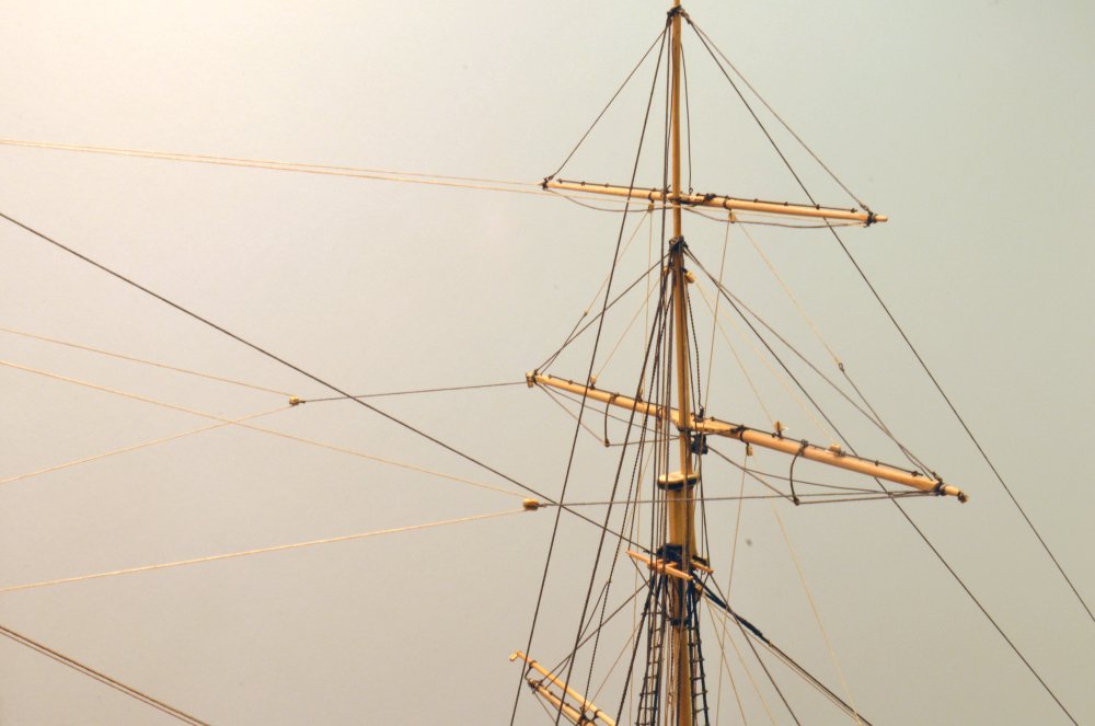
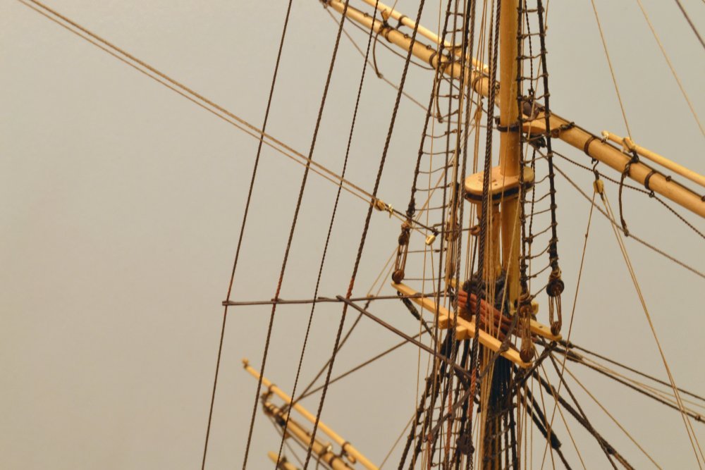
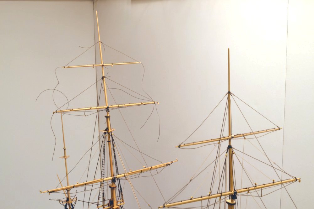
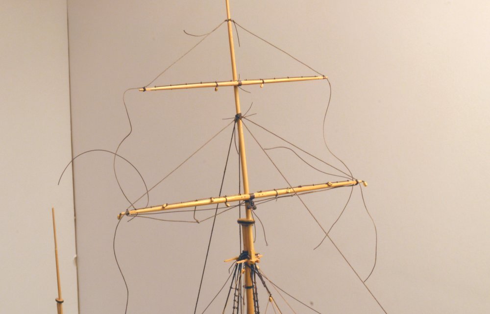
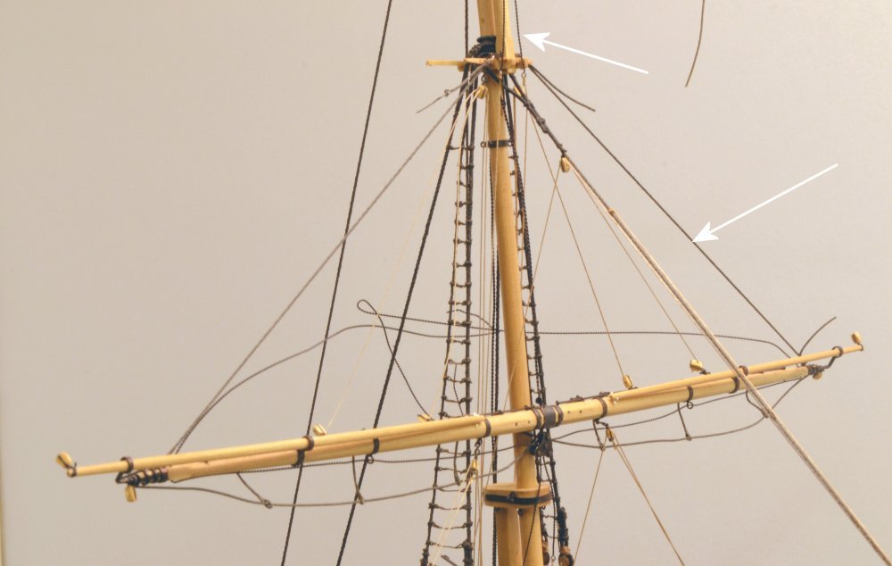
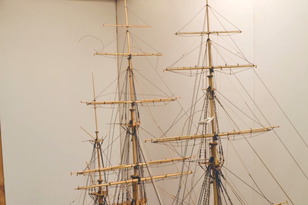
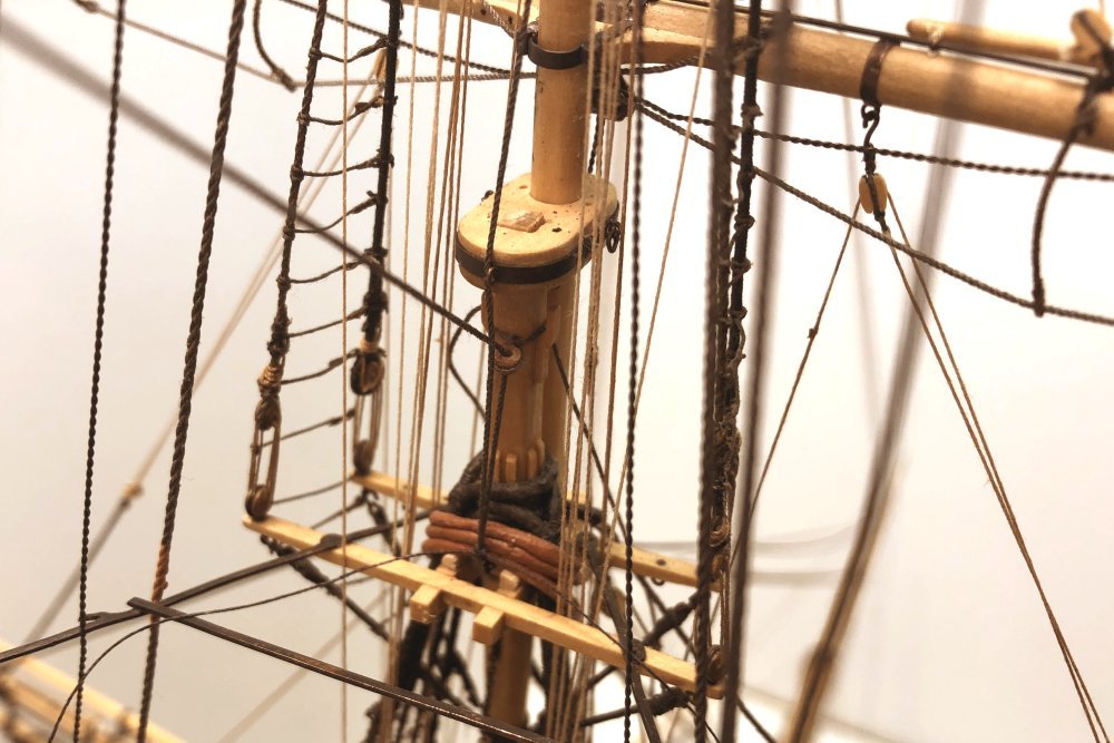
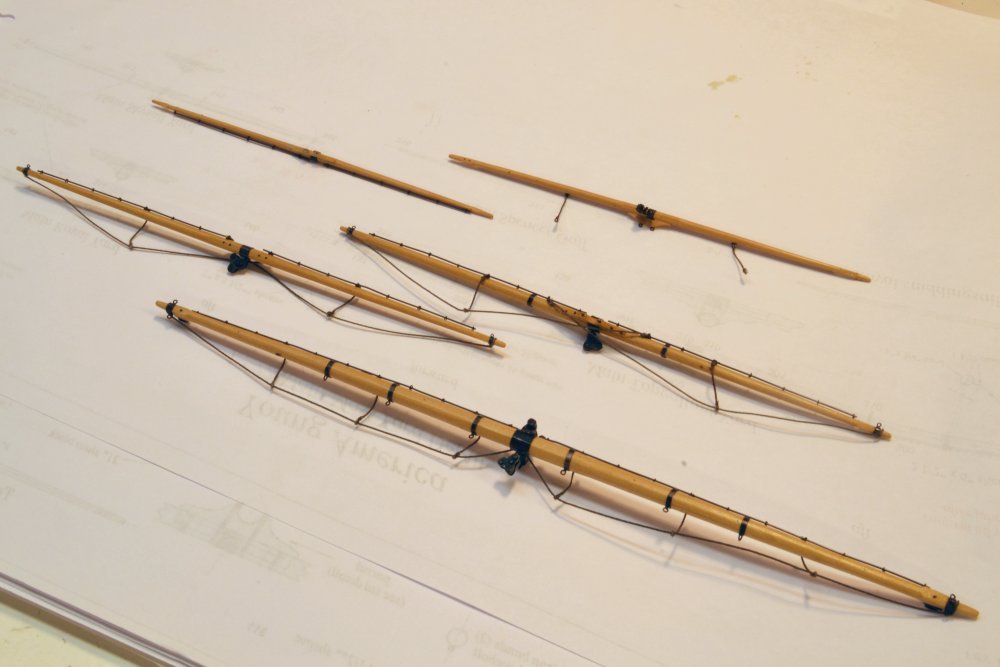
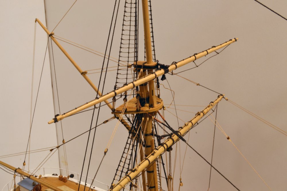
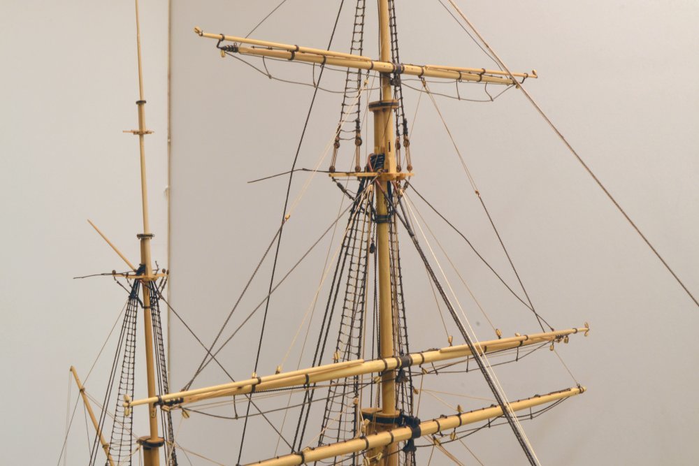
Young America - extreme clipper 1853 Part 317 – Upper Yards - Main On the fore upper yards, I attached most of the rigging, including the long lines of running rigging, to the yards before erecting the assembly of the pole mast with the royal and skysail yards mounted. This was a bit of a mess, due to of the number of lines and also because many needed to be coiled to avoid tangle. This left some kinked and fuzzy. For the main upper yards pictured below, only the standing rigging, and not all of that, was attached at the bench. In the picture, the royal stay and royal backstays go down at the bottom of the picture. Standing lifts were installed over a grid to help level them. I noticed later the missing footropes on the skysail. These will have to be fitted later on the model. Can't wait. The next picture shows the above assembly erected on the mast. Despite best efforts at the bench, the port, royal standing lift had to be removed and installed in place to level the yard. Some loose ends need to be clipped off and the wire sheet chains are still on the loose. The next picture is closer. The next step was to run the falls from the two skysail sheet chains dangling below the center of the royal yard. That has been completed in the next picture. The upper arrow points to one of the skysail sheets. These run all the way down to the main deck, passing through fairleads in the main top. After belaying, these lines get a lot of tension adjustment to pull down evenly on the yard and make the standing lifts – lower arrow – taut. To do this, I pull down on the fall with tweezers above the pin, then haul on the loose end. No glue on the belaying point until all the lines are run and adjusted. The next picture shows the fore and main upper masts. The height of these masts is impressive – the main extends 180 feet above the deck. The fore royal stay has been run in this picture. The tension between that and the two backstays sets the straightness of the mast. The last picture shows the lower end of the main royal stay. The 4 1/2" stay descends from the upper left corner of the photo through a bullseye strapped to the main topmast head. The loose ends of the splice between the masts have not yet been clipped off. The free end of the stay is clamped taut above the picture so the seizings may be tied at the lower end where it is fastened to an eyebolt under the leathered stays. The gang of stays and shrouds made this a difficult connection. I had to resort to a hook to the barely reachable eyebolt. A shackle on this would have made life easier, but too late for that. Drawing/Rigging List revision is pending for those that follow. An alternative sometimes used was to strap an eye to the top forward stay collar, but this would have had to be done before setting the collar. Ed
- 3,618 replies
-
- 36
-
-
- young america
- clipper
- (and 1 more)
-
Thanks, Dowmer. I agree with you on the sagging of lines, Its really a matter of degree. And, I would like to see them more stable. I do not expect to eliminate the drooping as long as its regular. Ed.
- 3,618 replies
-
- 3
-
-
- young america
- clipper
- (and 1 more)
-
Young America - extreme clipper 1853 Part 316 – Rigging Continued It has been more than a month since the last post, but work has been progressing. Most of it is not too photo-worthy, however. How many pictures of ratlines would be of interest? The last picture in the last post showed the upper yards for the main and mizzen masts with their ironwork completed. In the first picture below, some of these are shown with footropes added. The two on the left are the main royal and skysail yards. The three on the right are the mizzen lower topsail, topgallant and royal. The mizzen upper topsail seems to be AWOL someplace. I have still not made the broken mizzen sky yard. In the next picture the mizzen lower topsail is having a test fit on the mast. In this picture the pivot arm of the mizzen lower yard truss has just been replaced – note the bright copper retaining ring - after the pin through the yoke broke while I was rattling the topmast shrouds. The broken copper wire pin was replaced with stronger brass. This was some tricky work to do in place. Not shown above is the main topgallant yard, which has now been erected and shown in the next picture. The royal sheets that pass through the iron sheet block under the center of this have been run and belayed below. The topgallant clew lines have been coupled to the sheet chains and also belayed. These four lines serve to pull the yard downward. However, I notice in this picture that those lines have relaxed tension on the port upper topsail standing lift, so some adjustment will be needed to straighten that out. This is a normal part of the rigging process and is time consuming. The last two pictures illustrate the problem of humidity changes discussed in some earlier posts. The first picture shows the port main sail bowline as it has gone slack since the weather has turned cold – causing a drop in humidity. These were installed in the early, warmer, more humid fall. The next picture, without moving the camera, was taken less than one minute after wetting the line with clear water. The slack is completely gone. The 3" line is long staple, crochet cotton, size 40. It will sag again when dry. This occurs mainly on long lines, cotton and linen. I am testing treating the lines with some dilute polymer emulsion, either PVA or acrylic, to provide some moisture resistance and minimize this effect. Stay tuned. Ed
- 3,618 replies
-
- 35
-
-
- young america
- clipper
- (and 1 more)
-
Thank you all for these comments and seasons greetings. Andre, if you were able to wade through all the posts, you have my admiration, to say nothing of thanks. Its been a while since the last post, not because I am laying down on the job, but there has not been much interesting to show, unless you want to count ratlines. A couple hours a day "rattling down" is about my limit. I am starting to rig the yards shown in the last post and I will try to get some pictures of those posted soon. Ed
- 3,618 replies
-
- 8
-
-
- young america
- clipper
- (and 1 more)
-
Mark, on Naiad, I photo-etched brass rings on capstans, stove parts, plate knees. I would think gun door hinges, chain plates would be good candidates - if you enjoy photo-etching. I did not, particularly. A bit messy - nasty chemicals. On suggestion I would make - keep the black areas on your masks to a minimum - they eat up the etchant. Forexample, you may wish to add dummy white areas between the crests and whited rectangles into the black areas around the hinges. Ed Ed
-
Thanks for all these comments on the yards, everyone - and the likes, of course. You get a lot of practice making these on this model. Except for that last mizzen sky yard, all this should now be finished, and along with it the last of the woodwork on the model. That I regret. There something relaxing about shaping wood after fussing with small metal parts and rope. Have a great holiday, everyone. I guess we will re-connect in the new year. Ed
- 3,618 replies
-
- 13
-
-
- young america
- clipper
- (and 1 more)
-
Lovely work on the outer hull details, Paul, and the quarter gallery windows look great -interesting and challenging work with all the crazy angles and curves. Wow, that is some destructive effect on the planking, Paul. I have the same questions as, Druxey. I wonder, did you use dry heat to shape the planks, and then directly install? I know for example if you boil plank for bending and do not let it dry before installing that significant gaps will form - perhaps the opposite effect of what you have experienced? Very peculiar.
-
HMCSS Victoria 1855 by BANYAN - 1:72
EdT replied to BANYAN's topic in - Build logs for subjects built 1851 - 1900
Very nice work on tiny pumps, Pat. Also that rigging document is a real find. I look forward to seeing that work. Cheers, Ed- 1,013 replies
-
- 2
-
-
- gun dispatch vessel
- victoria
- (and 2 more)
-
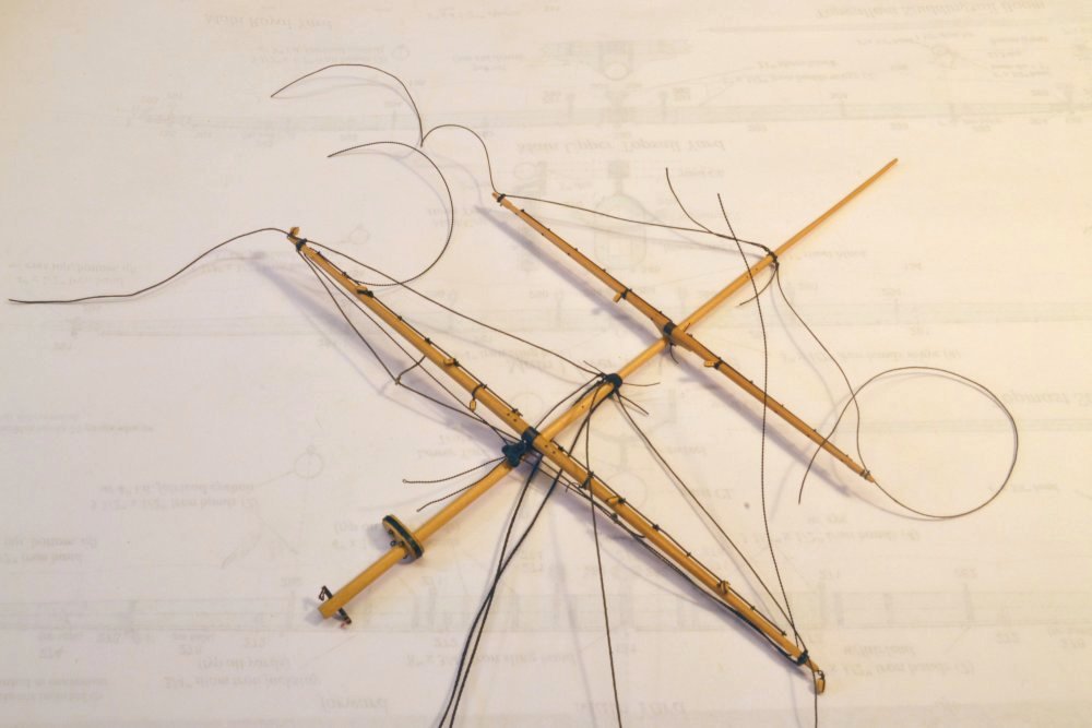
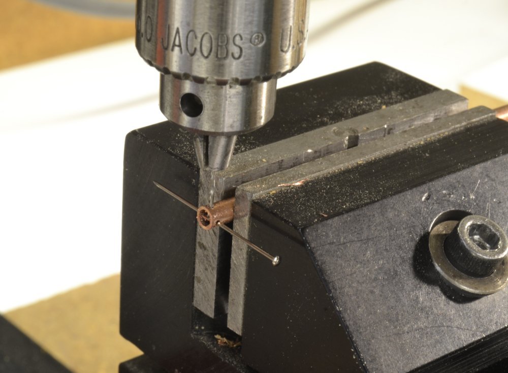
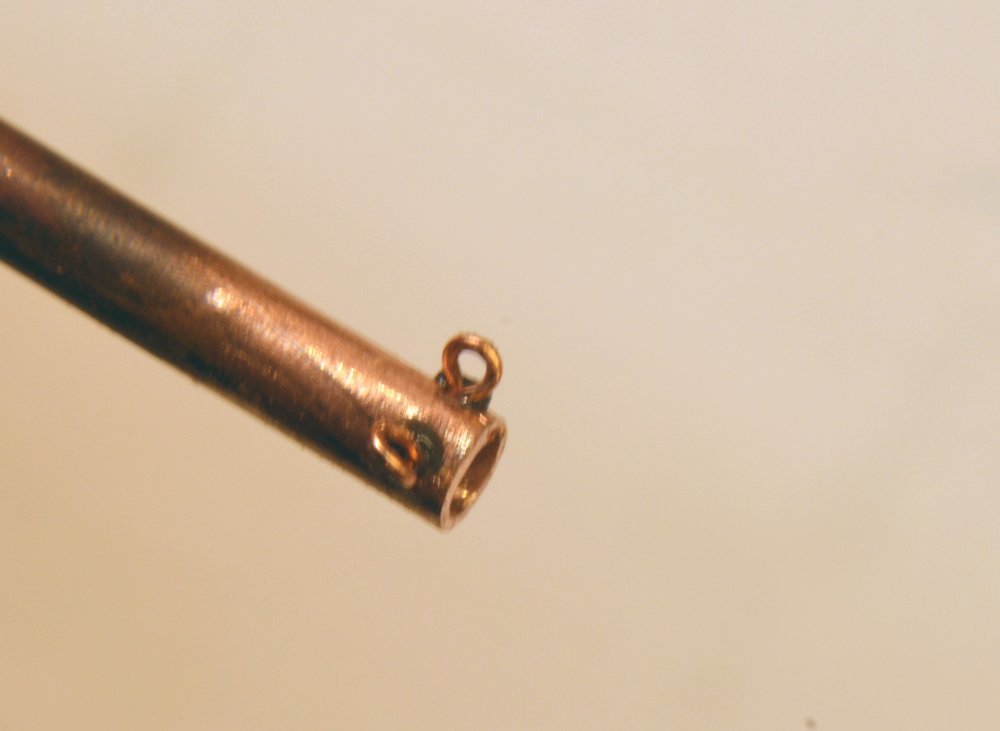
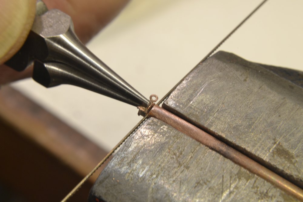
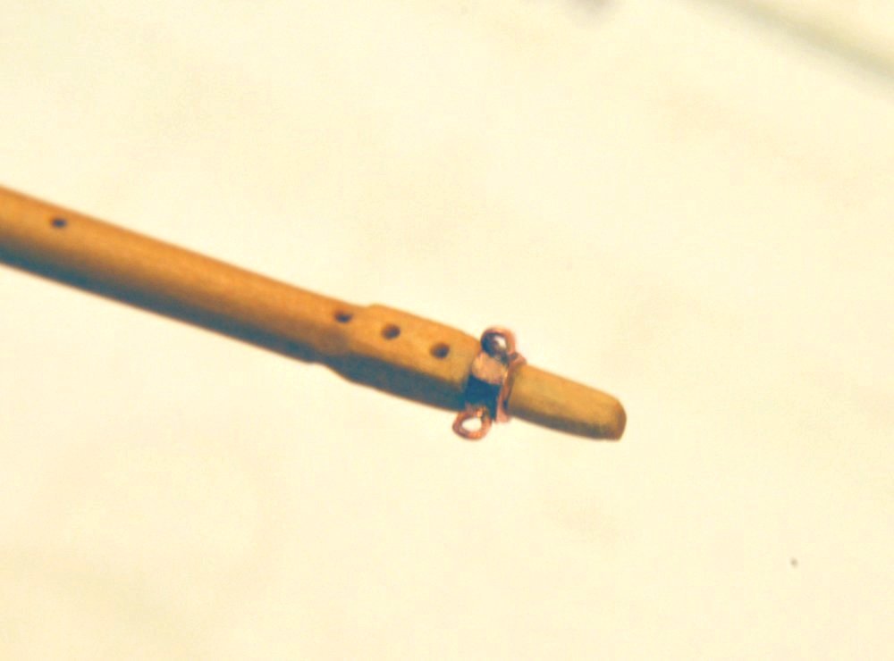
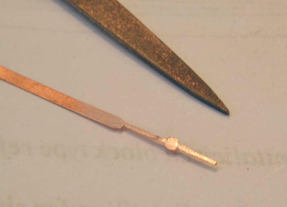
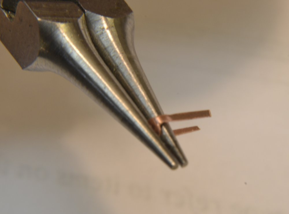
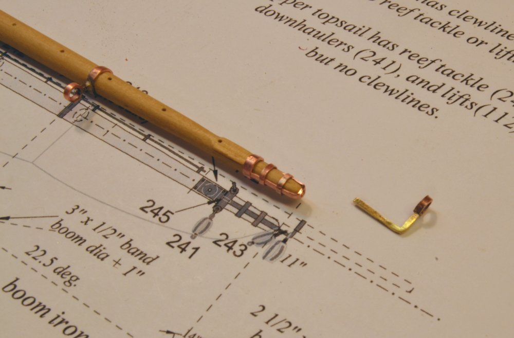
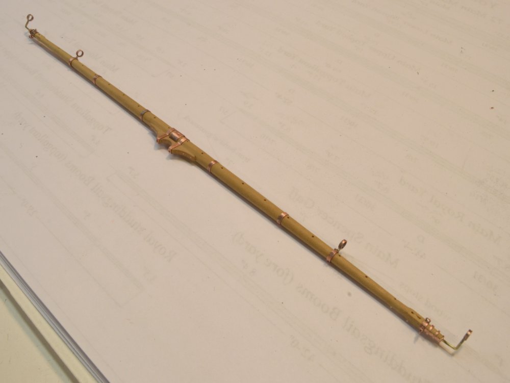
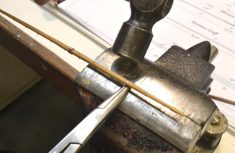
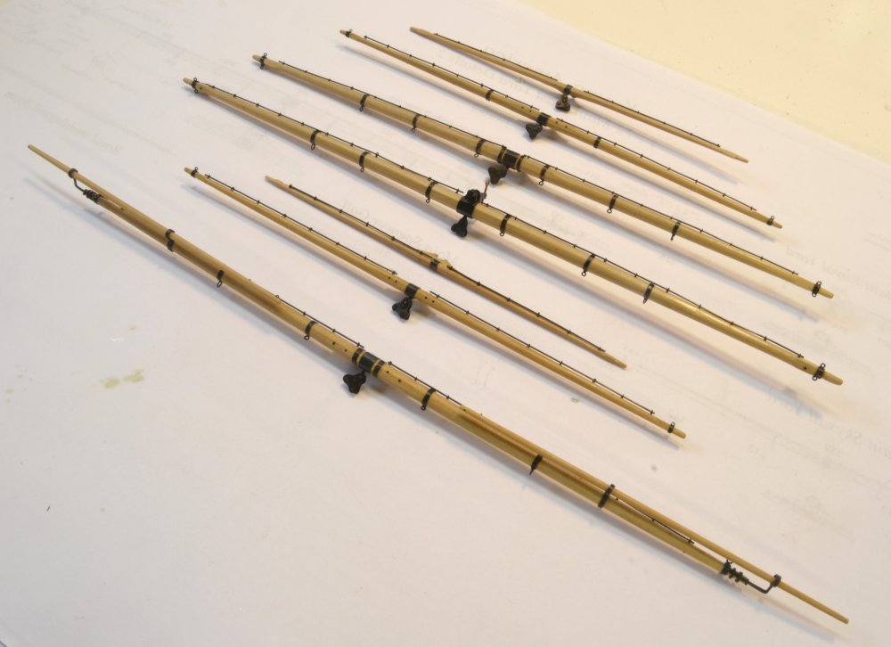
Young America - extreme clipper 1853 Part 315 – More Yard ironwork So, except for a few parral straps and the unfortunate mizzen skysail yard, all the remaining yards are now made and fitted with their ironwork. This post describes the final steps in completing those yards. On the largest yards, the yardarm bands were fit over the arms then drilled for their eyebolts – usually two or three on each. With the smaller yards, this drilling into the wood weakens the yard arm, so prefabricated bands with soldered-in eyebolts were made for these. I believe I described some of the fabrication steps in earlier posts, but the first picture shows one of these being drilled. The first two holes were drilled through, and fitted with a pin to help set the piece in the vise with the side holes horizontal - for drilling the third hole. The copper tube used here was a very tight fit over the arm and was also filed around the outside to reduce its thickness. The next picture shows two eyebolts set into a tube with solder paste applied. After soldering, the bolt excess on the inside was removed out with an abrasive bit and a round file. The tube was then set in the vise to saw off the band. The band is held with pliers to prevent its flying or dropping to the floor when it is parted. Searching for these small, dropped parts is a major annoyance. A better method for this is to insert a length of wire into the tube above the saw blade when it is almost cut through to retain the loose piece. The next, rather poor photo, shows one of the smallest of these bands fit to its yard. This is a tight fit. The sheave in this yard remains to be carved out. The lower, upper topsail, and topgallant yards on the fore and main masts carry studdingsail booms for the top, topgallant and royal studdingsails, respectively. In this final set of yards only the main topgallant required these. The fabrication of the gear was described in an earlier post, but a few pictures of the work on the last of these is shown below. In the first picture the strap that reinforces the yardarm is being filed out of a copper strip. This is then bent to fit around the arm and the legs clipped to size. The bands are then held entirely by tight-fitting rings pushed over the end of the yard. The rings shown were cut from tube, then stretched with the small steel mandrel for a tight fit. The next picture of an earlier yard shows the band assembly and the other boom gear. The main topgallant yard with all it major ironwork is shown in the next picture. At this stage the jackstay stanchions – 28 gauge twisted copper wire eyes – were pushed into the holes previously drilled in the yards. The tightness of the fit in the .024" holes has proved sufficient, except on the small diameter yards where some additional holding power is needed. To avoid interfering with blackening, no glue has been used on the yards. The next picture shows the stanchions on a small yard pushed through, clipped off, and then peened on the underside. In this step the pliers hold the eye of the stanchion and act as an anvil for the light tapping of the hammer. No, this is not how the mizzen skysail yard was broken. With these installed, the ironwork on the yards was blackened and the remaining minor fittings added. The final set of yards is shown in the next picture. The ironwork was blackened with liver of sulfur solution brushed liberally over the yard, followed by progressive rinsing under a cold water tap. When thoroughly dry, the blackened brass jackstays were pushed through the stanchions. Other inserted eyes and the sheet blocks were then glued in with CA and a light final finish of wipe-on polyurethane applied over wood and metal. In the picture the lower three yards are the main topgallant, royal and skysail yards. Those above are the mizzen yards from the upper topsail to the royal. These yards are now ready to be rigged and mounted. Ed
- 3,618 replies
-
- 51
-
-
- young america
- clipper
- (and 1 more)
-
I never use emoticons, Druxey, but I attempted it to show my comment on the likes was in jest - a wink and a smile. All sympathy is appreciated - humor helps as well. Tom, I dug up a photo showing the octagonal mandrel. When using this to stretch an octagonal ring, the octagon should be formed on the mandrel before stretching. Except for the piece on the left, these are all hard maple. If I anticipated many more years of modeling, I would make these in brass, or perhaps just a harder wood, like box. Also, the tapers need to be very gradual. The diameter of the 12" long octagonal mandrel goes from about 3/32" to 3/8" at the large end. The large one on the right was used for mast rings.

- 3,618 replies
-
- 21
-
-
- young america
- clipper
- (and 1 more)
