
HOLIDAY DONATION DRIVE - SUPPORT MSW - DO YOUR PART TO KEEP THIS GREAT FORUM GOING! (89 donations so far out of 49,000 members - C'mon guys!)
×


EdT
-
Posts
2,214 -
Joined
-
Last visited
Content Type
Profiles
Forums
Gallery
Events
Everything posted by EdT
-
Can't help there, Randy. I sized all my own pieces from large stock as described in the book. Ed
-
Nothing on the burner right now, Daniel. Very busy with two virtual learners here every day. Ed
-
Randy, drawing 8, actually 8b, is the baseboard plan for the 1:96 model. You do not need this for 1:72. Attached is the full list of provided drawings for each scale, excluding the many letter-sized sheets on each CD. Note that the baseboard plans are pdfs and not provided as printed drawings. Also, drawing 11, included with Volume II is 1:96 scale which should be adequate to use for both scales for the Volume II work. Same goes for Drawing 12, the belaying plan. Because no measurements need be taken from 11 or 12, no 1:72 versions were included. Hope this helps. Ed Appendix 2 - Drawing List.pdf
-
HMS ROYAL KATHERINE 1664 by Doris - 1/55 - CARD
EdT replied to DORIS's topic in - Build logs for subjects built 1501 - 1750
Fantastic work, Doris. Certainly the best model sails I have seen. Ed- 1,035 replies
-
- 5
-

-
- royal katherine
- ship of the line
- (and 1 more)
-
I now recall that I only partially covers the space between the hold common plank and the keelson. There is no hard copy of drawing 8. This is the base plan and was provided as a pdf on the CD so replacement copies could be printed when the print glued to the board got soiled. Common mistake. Check your CD. You must have a copy of this on your board. Ed
-
The first thing to recognize, Randy - you may realize this already - is that the limber channel on this ship is actually outside of the frames, see p 189. The first strake inboard, next to the keelson is shown wider than the other common planking as may be seen in Fig 8-38. This was an arbitrary sizing on my part, perhaps consistent with what I had seen on some other drawings - can't remember. I would assume this last space would be covered with lengths of common plank of wider width. You can use your judgement on this. I believe the common method of clearing clogged channels was to have a chain in the channel - not shown on model - that could be used to clear debris and allow water to flow into the well. Keep in mind also, that bilge pumps used on this ship were of the suction type, allowing the pipes to be located right down on the outer planking bilge strake - unlike earlier chain pumps that could only reach the tops of the frames and therefore left standing water between the frames if no between frame fillers were used. In any event, most of this construction will not be visible on the finished model. Hope this answers your question. Ed
-
Great to hear from you, Remco, but not so great to hear of your recent trials. Hope all is well and things look up for you in the new year. 2020 has not been great for many of us, but hopefully we will all head back to normal next year. All the best. I look forward to seeing your work again on MSW. Ed
- 1,215 replies
-
- 6
-
-
- sloop
- kingfisher
- (and 1 more)
-
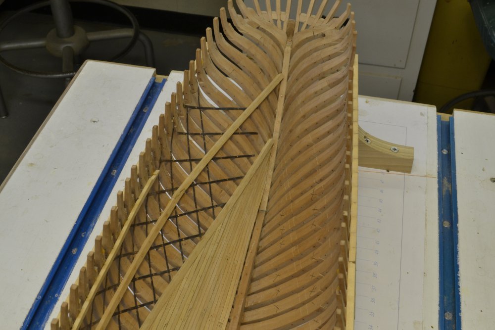
Ah! Now I understand your question. It is a good one. I did have to go back and reconstruct the reasoning I used in the design of the model. I should preface my answer by saying that not much is known about many of these structural details for any specific ship. If you refer to the cross-sections in Crothers book on clipper ship construction, you will see that a variety of methods were used to reinforce these long hulls against hogging. I based the Young America model design on the Crothers cross-section for YA which was based on better information available for Challenge, Webb's preceding design. Webb's design did not employ large section bilge keelsons used by some builders, but relied on bands of thick members (bilge ceiling) running from the underside of the lower deck clamps down to below the line of the floor timbers. These 8" square(?) timbers were scarfed and bolted to the frames and to each other. If you compare the midship frame drawing with the midship cross-section (both included on the cd) you will see that at midship the heavy band of bilge ceiling begins about 5 strakes below the line of the floor timbers. The strakes of these ceiling members then parallel the line of floor timber ends over the length of the ship, tapering down to end where the fore and aft tops of floor timbers intersect the lower deck clamps. Thus, the bilge ceiling does not extend all the way to either the deadwood aft or the stem. By running the bilge strakes on a different line (actually a hull diagonal) from the deck clamps, a sort of truss structure was created that would significantly stiffen the hull. This would provide increased strength over a design where all the planks ran parallel. While the extent of heavy bilge ceiling could be increased to take it all the way to the ends of the hull, this would involve more strakes of heavy timber below the floor heads - an expensive proposition offering small benefit at the ends of the ship where the hogging effect would be less and where the deadwood and stem structure provided their own stiffness. In summary, the strakes of bilge ceiling run parallel to the floor heads with the lower edge of the band five strakes below those heads. This interpretation may or may not be correct - who knows - but that was the model design basis. I attach the referenced frame and cross-section for those who may not have the book. Thanks for the question. Ed Midship a.pdf Cross-Section at Midship.pdf
- 3,618 replies
-
- 1
-
-
- young america
- clipper
- (and 1 more)
-
Randy, I do not understand your question. Can you give me a reference - photo or drawing - that shows this not extending the full length? Are you looking at where it stops for the view port openings? Ed
-
You are welcome, Randy. Glad if I can help. I do know the effort involved to keep up an informative build log - almost as much time as spent on the model, especially when you consider photography. I probably went overboard posting pictures - around a dozen a week for a few years - and taking them for both the blog and the books - 200 to 300 per month four several years. It is a lot of work - to say nothing of constantly tripping over the tripod in the workspace. Again, good luck with your project. Ed
- 3,618 replies
-
- 1
-
-
- young america
- clipper
- (and 1 more)
-
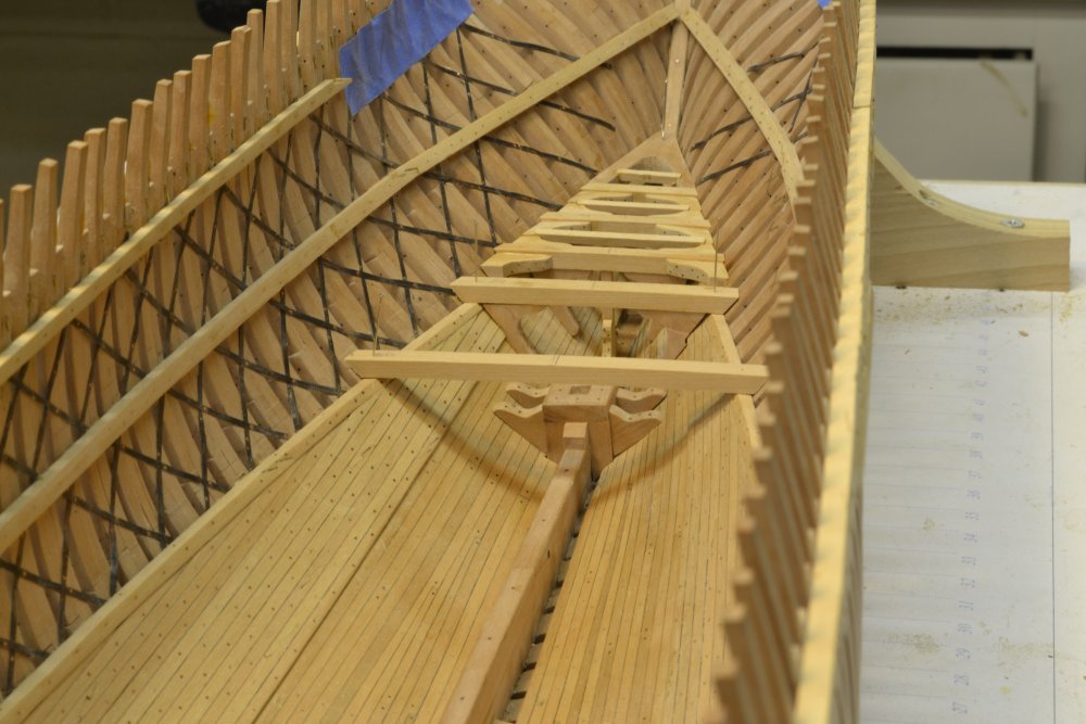
Hello again Randy, This seems to be the one photo I have of the clamps at the stern. Keep in mind that the clamps will be severely dubbed off level on the tops to provide a flat horizontal surface on which to bed the deck framing. This was done later, after this photo was taken and before the beams were fitted. It is important when fitting these clamps that the height of the clamps as shown on the drawings sets the clamp height at the frames. The inner upper corner will be dubbed off. Note that the stern deadwood is not high enough above the cutting down line to allow the clamps to be fayed into it, so the clamp ends are just squared off. The second picture shows this area after the deck hook and some of the lower deck framing was fitted. Hope this helps. Ed
- 3,618 replies
-
- 3
-
-
- young america
- clipper
- (and 1 more)
-
Hello Randy, History has not decided whether Young America's strapping was internal or external, so one cannot argue for either with any certainty. I tried and failed to uncover this. I believe the structural implications are equivalent, but the difference in installation difficulty between the two is not. Slotting frames to fit the straps inside would have been much easier and faster than scaffolding and doing this on the outside of the frames. Much of the work would be overhead. Because time and money was driving the building of these ships, I chose the internal option in the absence of any definitive documentation. One could argue for either method. For some reason I cannot recollect, I began fitting the bilge ceiling before the entire lower deck clamps were installed, but in no case did I install this ceiling before the ends of the clamps were fixed. This is necessary so that the ends of the ceiling timbers can be tapered to fit neatly to the underside of the clamps. Installing the clamps completely before starting the ceiling is not only acceptable, but probably preferred. Go for it. If you are planning a build log, I would love to follow it. Ed
-
A feat of endurance no doubt, Adam. Thank you for your interest. I hope you found something useful. Cheers, Ed
-
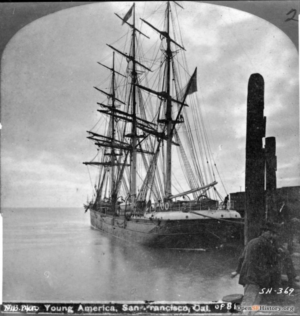
Now I am not so certain, Tony. On closer inspection and comparison with the drawings, the lower rail along the side appears very low. Also, the main and fore shrouds seem to be anchored inside the hull. That, along with the rounded poop - which could have been added - raises questions. Otherwise she seems a dead-ringer. I wish the picture of the stern below the poop were clearer. Ed
-
Hello everyone, Maury S recently referred me to a site featuring photos from San Francisco history and this previously unknown - at least to me - picture of Young America was in the collection. Although the built up and rounded stern was something new to me, the rest of the picture leaves no doubt that this is indeed Young America - late in her career for sure. The rounded stern modification suggests to me that the entire poop deck was raised, including the helm, perhaps to increase head room in the cabins below, or to raise the cabin deck level to the height of the main deck - note portholes. More stowage capacity? The original cabin deck was a "mezzanine" between the main and lower decks. Very curious. Ed
- 3,618 replies
-
- 4
-
-
- young america
- clipper
- (and 1 more)
-
HMCSS Victoria 1855 by BANYAN - 1:72
EdT replied to BANYAN's topic in - Build logs for subjects built 1851 - 1900
Pat, I can offer opinions on your questions, but they are just that, based on the conclusions I reached in interpreting the various sources while constructing Young America. The questions relate to very small details. You may be overthinking this. However, Q1. I would say no, the extreme rake of the masts notwithstanding. I do not believe it would be practical or important to angle the stops to avoid additional bend in the stay at the eye splice (or seizing) due to rake. I have seen no details of angled stops in any spar drawings. Q2. My guess is that, in general, major structural elements. like crosstree assemblies, would not be constructed with bevels in the members and that where necessary wedges or shims would be used, Again, I have seen no references showing bevelling of furniture framing. I notice that you show the cap in two different ways - horizontal and right-angled to the mast. Based on Fincham's construction specifiation for caps, at least, the right-angled (not horizontal) configuration would be correct, in spite of the fact that many diagrammatic spar plans of the period show these horizontal. I cannot explain these differences, but would go with Fincham based on the difficulty of shaping angled mortises - square and round - when making the caps. Q3. I would go with square fid holes. I assume the fids would be standard iron bar stock and would rest on iron plate and believe this would be OK. Again, have never seen reference to angling fid holes in any reference. In general, I believe mast rake could be adjusted. While not likely to be done very frequently, if at all, this would obviously upset any precise bevelling features that were built in to either the spars or furniture. Hope this helps. Ed- 1,013 replies
-
- 4
-
-
- gun dispatch vessel
- victoria
- (and 2 more)
-
Randy, I just use ordinary high speed steel drill bits. I believe the size of the holes is about 1/8"? Should be able to drill through most metals with that, certainly brass. Bits should be sharp, not old and dull, of course. Important to center punch as always. Let the drill do the work and do not use too much pressure. Medium speed. Should work without problem. Ed
-
Randy, After center marking, I would clamp it down against a fence to keep it from spinning, then drill with the press or by hand if necessary. Holding it down is important. A spinning strip can be dangerous to your fingers. Ed
-
Hi Randy, I do not believe you can go wrong with the Sherline tools. I have found them to be excellent, with an excellent array of additional accessories - all of high quality. So I do not hesitate to recommend. Greg's suggestion sounds like it would be very useful, though I have not seen the videos. I also found the book, Tabletop Machining, by Joe Martin, the late owner of Sherline, to be very good and written for people like us. The manuals that come with the tools are also very good. In the Naiad and Young America books, I did my best to describe machining steps in some detail, recognizing that, like myself, most modelers are not trained machinists. There is a learning curve. As with all good tools, the Sherline machines plus the necessary accessories, will be costly. I suggest buying them progressively, rather than all at once, adding accessories as they are needed. I believe in YA Volume I, I discussed which would likely to be needed first for a model of that type. You might want to have a look at that. All the best, Ed
- 3,618 replies
-
- 2
-
-
- young america
- clipper
- (and 1 more)
-
HMS VICTORY 1765 by albert - 1/48
EdT replied to albert's topic in - Build logs for subjects built 1751 - 1800
Lots of frames, Alberto! Beautiful work as usual. -
HMCSS Victoria 1855 by BANYAN - 1:72
EdT replied to BANYAN's topic in - Build logs for subjects built 1851 - 1900
The model is looking fantastic, Pat. You might be splitting hairs on your questions, Pat, but I understand how wanting to get this detail right works on our brains. I suspect much of this detail was left in the hands of the shipwrights, so it maybe hard to go wrong. Cheers, Ed- 1,013 replies
-
- 4
-
-
- gun dispatch vessel
- victoria
- (and 2 more)
-
Nice work as usual, Gary. Making that functioning steering gear was one of the tasks I enjoyed most in building Naiad. Trying to remember how I joined those loose ends at the wheel spindle - time flies. Ed
-
Hi Randy, Thank you for remembering that the List Of Dimensions takes priority. I assume you are referring to the aft frames 43a, 44a, 45a, which indeed show 2nd futtocks at 12" in conflict with the LOD that specifies these at 11" - a good example of why dimensions should be shown in only one place. I probably could not resist putting sizes on the pattern sheets for clarity and ready reference. A trap. Because the LOD was created directly from my sources before making any drawings, using those dimensions is probably best - in this case and in general. The difference on these pieces is slight ( 1" = .013") and I believe they will be planked over. I cannot recall what I used, but would not be surprised to find it was the drawing dimension. Thanks for raising this point. Keeps me honest. Ed
- 3,618 replies
-
- 3
-
-
- young america
- clipper
- (and 1 more)
-
I will take a look later this morning, Randy. Stay tuned.
-
Slackwater, I believe the text is quite clear on this. The futtocks should not be sided until after assembly if you are using this method. To quote from Ch 5: Although frame components diminish in siding from bottom to top, all of the pieces should be cut from stock that is the thickness of the lowest parts, the floors or the lower futtocks. This will allow the frames to lie directly on the pin board without spacers under the upper parts during assembly. It will also provide an accurate basis for beveling. The sidings are smaller toward the ends of the hull, so check the List of Dimensions. The upper futtocks will be cut back to their correct sidings after beveling and removal of the patterns. The initial toptimber sidings are an exception. On the finished model, they will be prominently lined up along the main deck where any small difference in size will be very noticeable. You will recall the quality criteria relating to uniformity of similar parts. All of these toptimbers, two on the forward frame of each pair, should be cut out from 9” thick stock to ensure their identical width. These will be attached after the other parts of the frame are assembled. Ed
- 3,618 replies
-
- 1
-
-
- young america
- clipper
- (and 1 more)