HOLIDAY DONATION DRIVE - SUPPORT MSW - DO YOUR PART TO KEEP THIS GREAT FORUM GOING! (Only 68 donations so far out of 49,000 members - Can we at least get 100? C'mon guys!)
×


EdT
-
Posts
2,214 -
Joined
-
Last visited
Content Type
Profiles
Forums
Gallery
Events
Everything posted by EdT
-
When using pigments to darken glue, I have found that very little is needed to produce dark glue when dry. I use about a teaspoon or two to a full six (or is it 8) ounce bottle of Titebond wood glue. I also found that slurrying the pigment in some watered down glue first - until it is completely syrupey - before mixing with the rest of the glue - improves the result including stronger joints. I believe this method helps encapsulate the pigment particles in glue and helps with cleanup. Of course, if alcohol is used to soften a joint later, the glue will disslove and release the free pigment. Ed
-
Merry Christmas to you as well, Tom - and to all the others who check in on this topic. I really appreciate your kind words and am very glad you find my posts helpful. Your comments and others like this make the effort of doing the posts - and the books for that matter - worthwhile. I also feel I have learned much from the methods described by others in their posts and would encourage more methods descriptions by all who post. Their is no "one way" or even a best way to do the various tasks we are all confronted with and all inputs of this type are valuable. Thanks again. Happy New Year everyone. Ed
- 3,618 replies
-
- 15
-

-
- young america
- clipper
- (and 1 more)
-
Look's like you are all set to go, Gary. All the best with the project. I look forward to following it. thanks for posting. Ed
-
Glenn, your modeling of the machinery is extraordinary. My hat - and I'm sure many other hats - is off to you. You did not mention cleaning and pickling in describing your blackening process, but it is clear from the results that you are doing a great job with that as well as the blackening process itself. The steps you mention make a lot of sense to me and I have done similar things with success. Trouble is, I often take short cuts that impair results and have not had the discipline to note what works well and consistently follow that process. Great job - and a very interesting project. Ed
-
Nigel, These could easily be made from wood, either by turning and milling as I did, or by hand methods. I would try turning a piece of hard wood like boxwood, castello or pear with the grain direction parallel to the lathe centerline. If you turn this between centers you will have centermarks at each end. Use those to mark the depth of the teeth with a compass. I would then slice off the gear and drill the axle hole using the centermark. The other end of the turning could be used to make the second gear. Than divide the circumference into equal parts - I did 36(10 deg) teeth on the ratchets and 18 (20 deg) on the stopper. You could then use a sharp edged triangular file to cut the teeth down to the scribed inner circle, remembering that the filed out triangular cuts are not equilateral - one leg of the cut is shorter. The grooves that contain the ratchet mechanism could be face turned on both sides after the gear is sliced off before cutting the teeth. Very hard wood is the key. I would then dye - not paint - the parts, using non-fading, pigmented material like thinned acrylic ink or India ink. Ed
- 3,618 replies
-
- 8
-
-
- young america
- clipper
- (and 1 more)
-
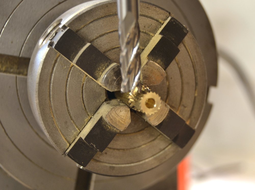
Thank you all for the nice comments and the likes. Rob, I am sure someone could construct a working 1:72 windlass from my drawings but not me. As I said in an earlier post, I considering making this a functioning model until I printed off the 1:72 drawing. It all seemed less daunting when working in real world 1:1 scale on the computer screen, so no, it does not work - at least not very well. Micheal, in this particular case - a 1/32" diam. end mill, cutting to a depth of .025" in wood - I felt quite safe with both the set up and the use of the drill chuck for this very low stress, non-precision work. Most of the light milling I do on the Sherline mill is done with collets, although I did use an end mill holder for the gear cutting. Both the collets and the chucks on the Sherline mill use a #1 Morse taper with both secured through the shaft with long bolts. I have never had a chuck or collet come loose - but thanks for the concern. Ed
- 3,618 replies
-
- 7
-
-
- young america
- clipper
- (and 1 more)
-
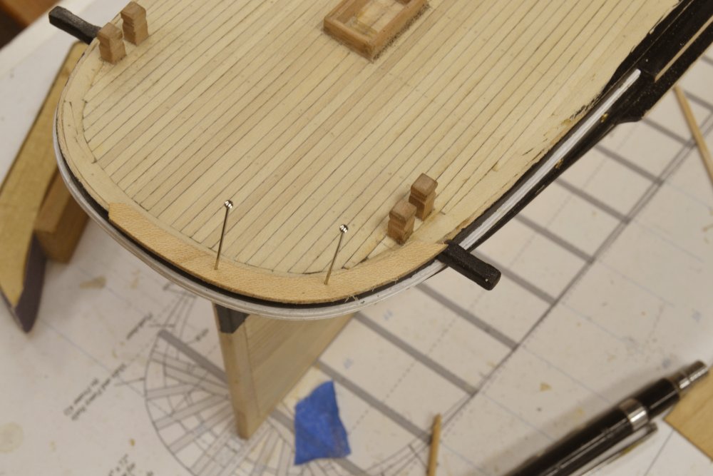
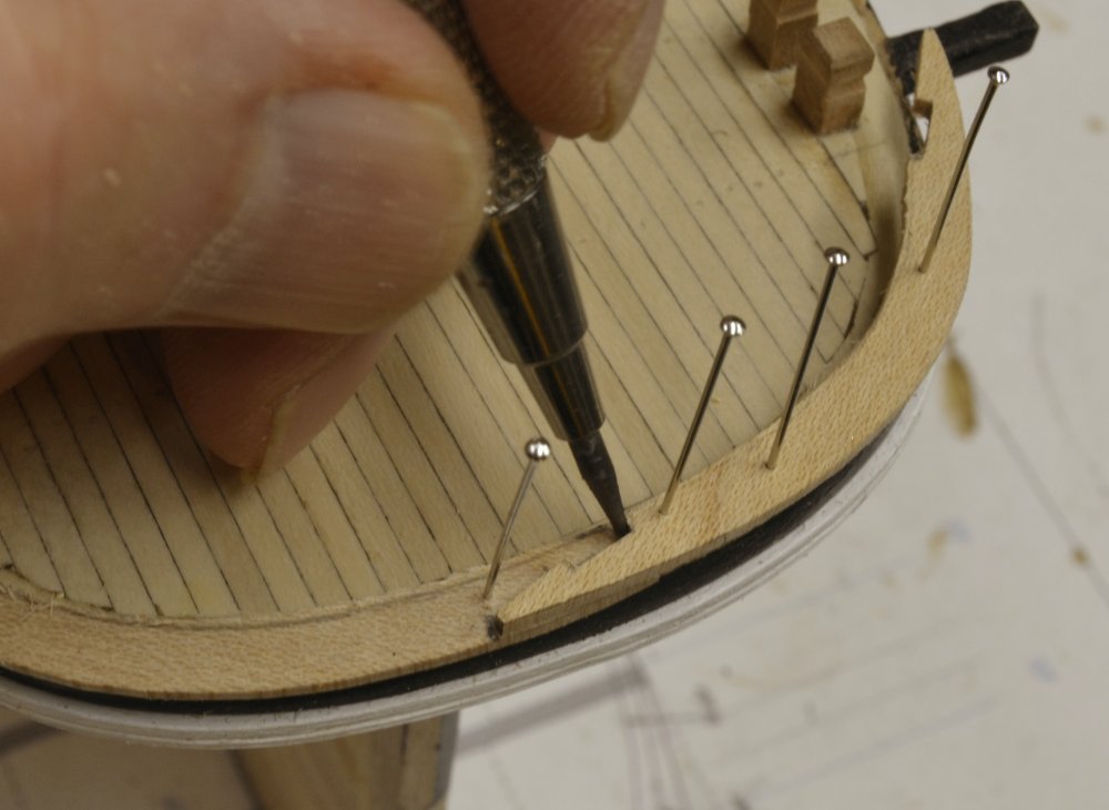
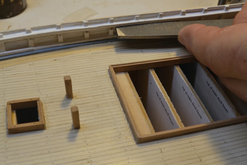
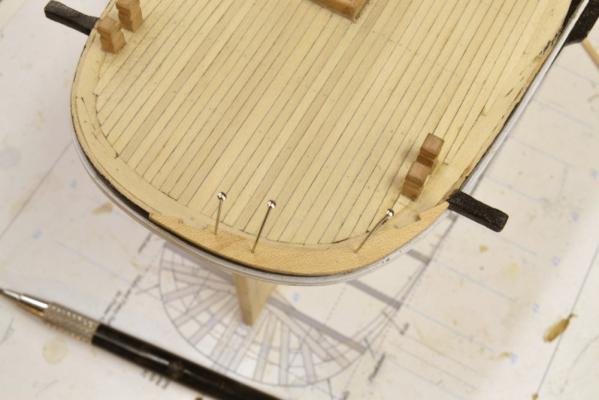
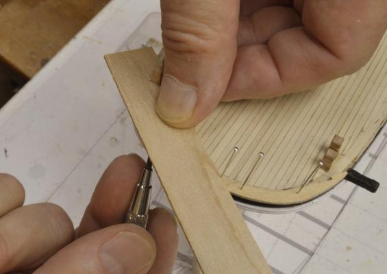
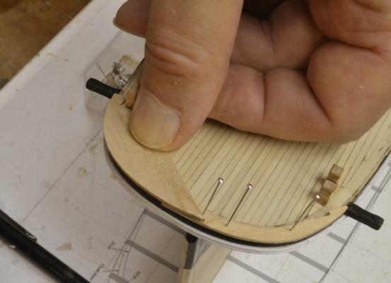
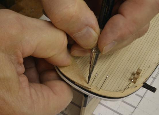
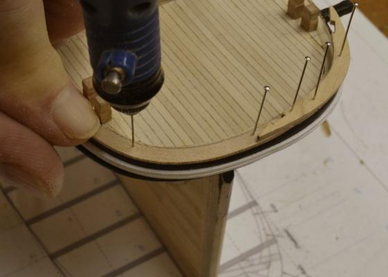
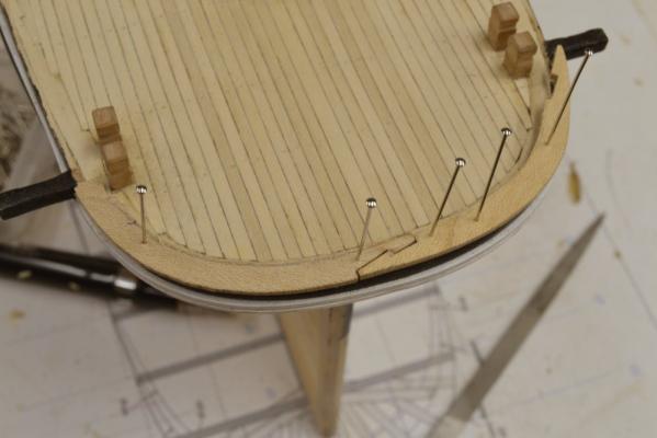
Young America 1853 – POB 1:96 Part 39 – Stern Fancy Rail The so-called “fancy rail” capped the tops of the bulwarks along the main rail, but at the forecastle and poop decks it also served to seal off and make watertight the top of the framing at the side. Although the curved margin plank below covered the tops of the timbers in these areas, this was not likely a caulked, waterproof joint. For this reason, the fancy rails at the forecastle and poop needed to be wide enough to overlap the outboard planks and also the inside margin plank by enough to permit good caulked joints. I wrestled with this because published sections through the bulwarks at the main deck generally show capping rails too narrow to meet the needs described above where they are at deck level. To resolve this, I decided to make the fancy rail wider at the end decks and step it down at the breast beams to a narrower width along the main deck bulwarks. A long story, but one that builders of the model should find useful. The work on the fancy rail started at the stern. The process for making the curved, hook-scarphed pieces was used on the margin plank below and on all similar pieces at both ends. Since I took a lot of pictures of the method on this rail, and since there are a number of these pieces to make, I decided to show the process that I use for this in some detail. Although it is covered in depth in the book for the framed model, this description may be of help to builders of this smaller version. In the first picture the first piece has been cut and pinned on the starboard quarter. Pin holes were pre-drilled for a sliding fit with the pins. The joint of the two stern sections will be on the centerline – staggered from the joints on the margin plank below. On this model all the pieces were cut from ¾” stock. I used this as a maximum thickness on this version so modelers could cut members to size with a good 4” circular saw and not need major tools like full size band(or circular) saw and thickness sander(or planer) that would be necessary if starting with the thicker stock that is needed for many pieces on the framed model. In this case the stock was readily available ¾” maple cut to a thickness of 3½” (just over 1/32”). It will be painted. In the next picture the scarph joints have been formed at the ends and the piece re-pinned in place. The piece extends about 3” outside of the outboard planking and covers about one-half of the margin plank. The piece was initially formed by the process shown below for the second piece on the port side. The ¾” width of maple strip was first marked to the shape of the stern from below as shown. The piece is being test fit in the next picture after cutting the outer curve. In the next picture end of this piece is being marked from the joint of the piece below. The full width of the piece was then marked out using a compass set to the width of the plank with an extended leg held to the outer curve. It was then carefully cut and shaped to this line. Care is needed because of the weak cross grain at the ends. I believe in an earlier post I pasted similar pieces to a scrap piece to protect the ends on a similar piece for cutting. The next picture shows the piece slipped under the first piece, fit into place and being drilled for locating pins. Once pinned the joint on the new piece can be marked out using a very sharp pencil as shown in the next picture. The joint was then cut on the second piece and fitted to the first as shown below. This picture was taken during the cutting and fitting process. Note that the joint has not yet been cut at the forward end of this piece. I will not describe cutting these joints since the method appears in a number of my other posts and is fully described in the book – and in the Naiad books. In the next part the side rails along the poop will be fitted and all these rails rounded off, painted and installed. Ed

- 191 replies
-
- 30
-
-
- young america
- clipper
- (and 1 more)
-
The wheel is fantastic, Remco. I have been experimenting with a similar tube device for turning small (.20") belaying pins, but using cutting tools - and not shaped. For that I found that the tube had to be quite strong and also had to hold the turning from moving up as well as back. Not too successful, I'm afraid, so I am using a different method for holding the 032" brass and using files, but not with a pattern. Your method using files looks like a winner - but I don't think I'd go as far as using it on cannons. They really do not need that kind of support, anyway - in my experience. Great looking work. Ed
- 1,215 replies
-
- 4
-
-
- sloop
- kingfisher
- (and 1 more)
-
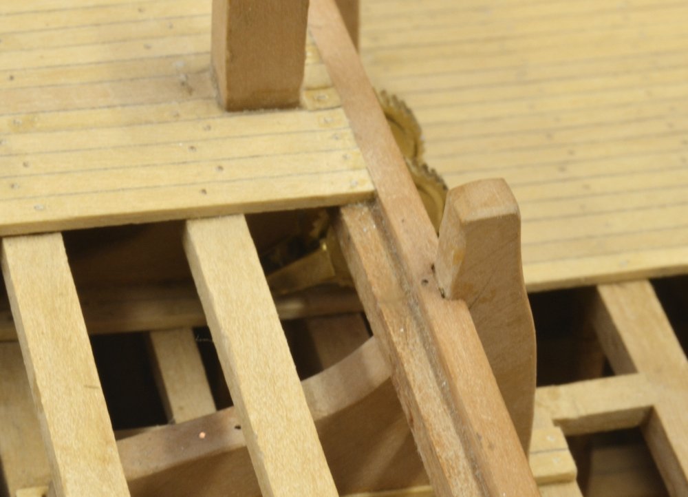
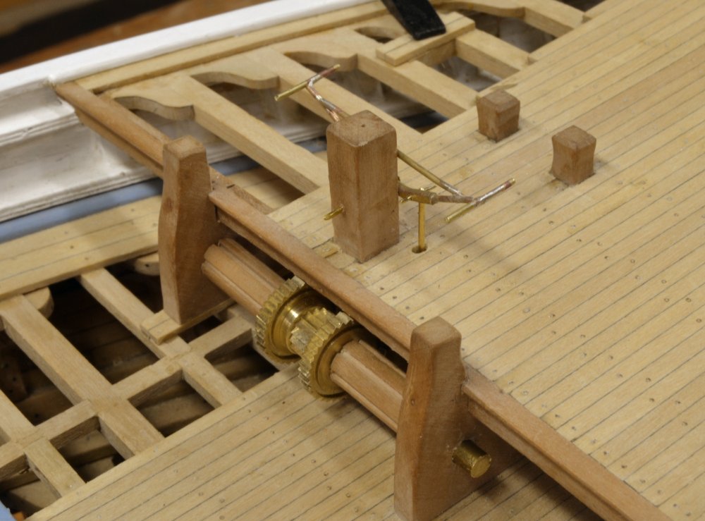
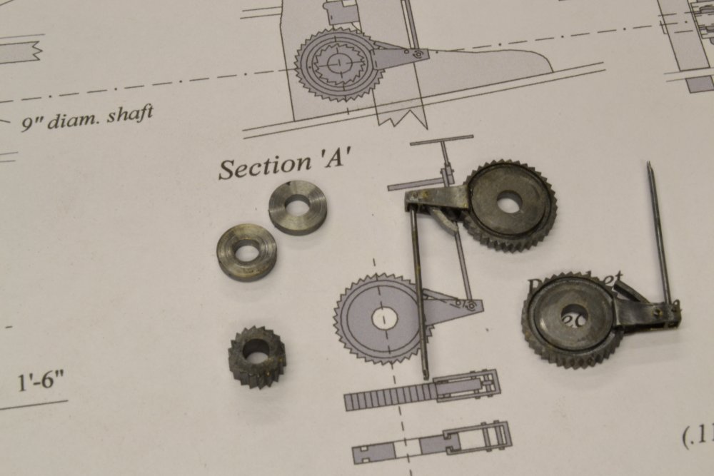
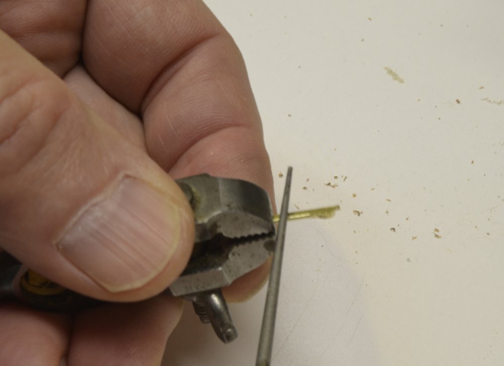
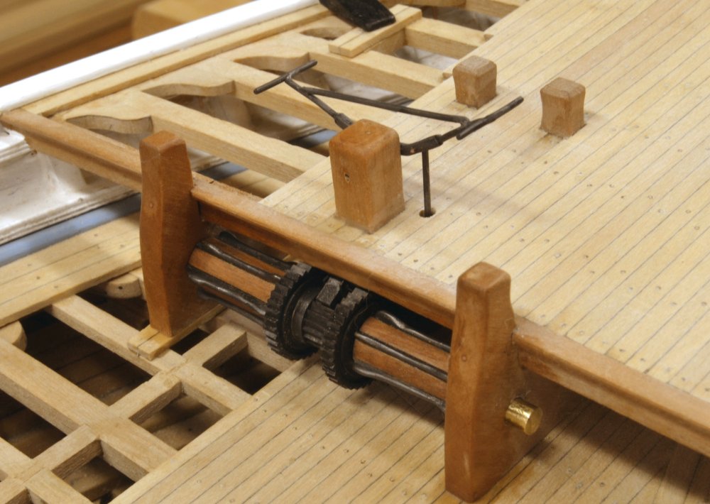
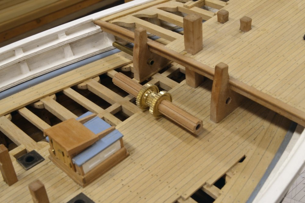
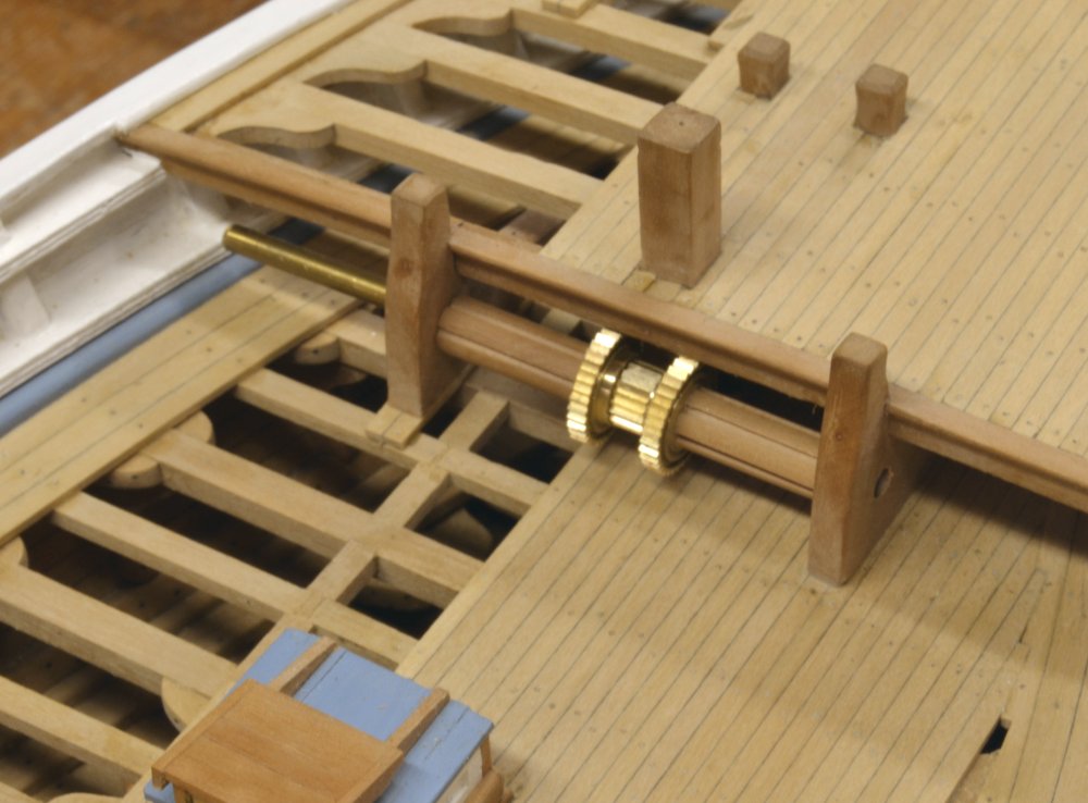
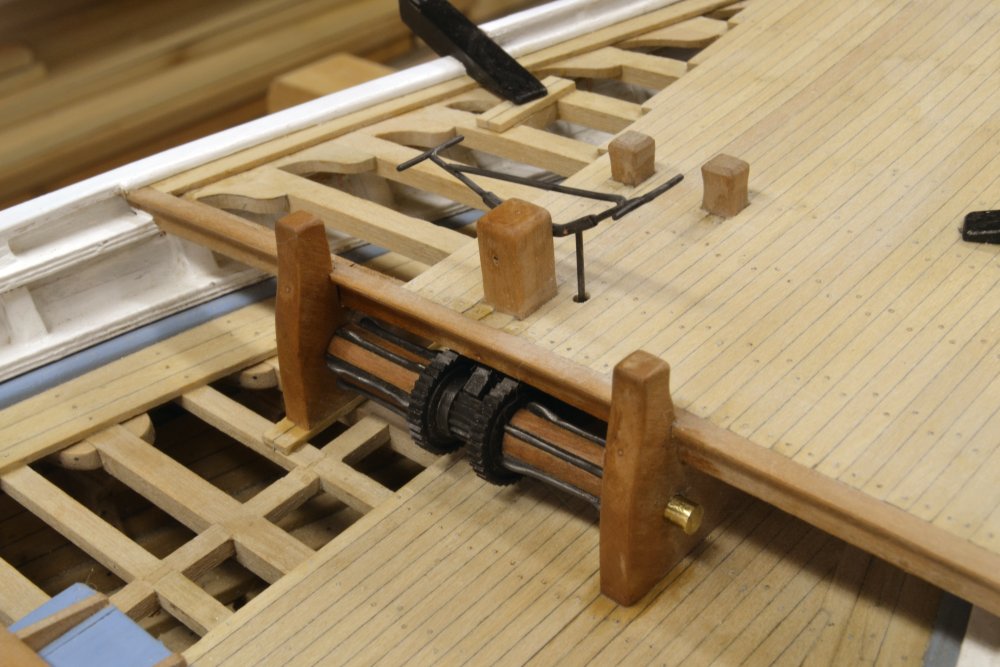
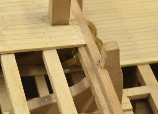
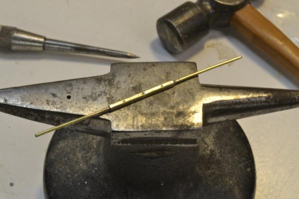
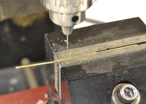
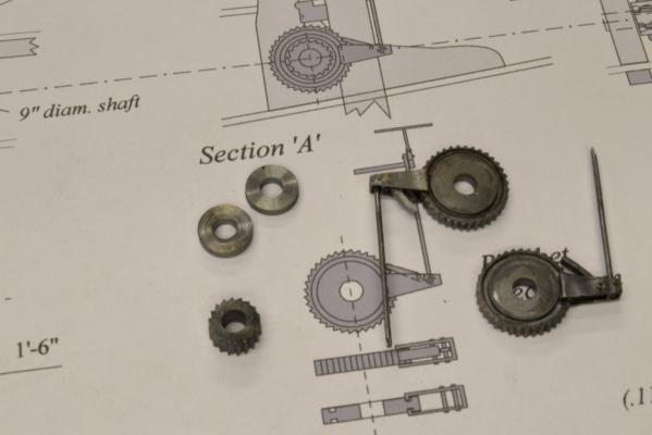
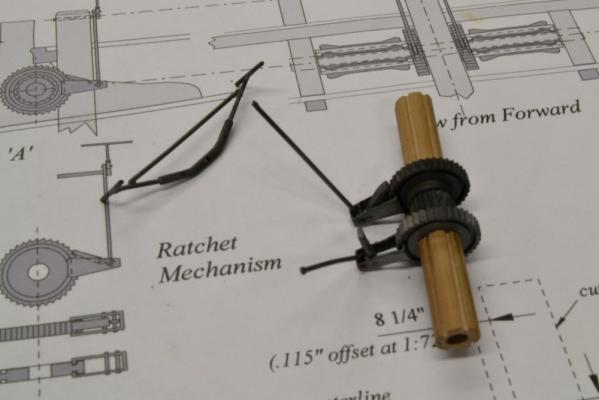
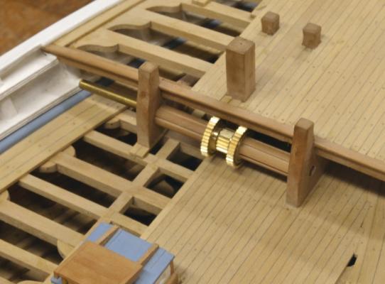
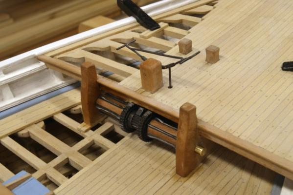
Young America - extreme clipper 1853 Part 130 – Windlass 3 The first picture shows about as much of the ratchet mechanism that will ever be visible on the model – below the open forecastle deck on the port side. This was taken just before the opening of the holes in the deck for the connecting rods on either side of the Samson post. The rods were then sized, flattened and rounded at the ends, and drilled for connecting pins. The next picture shows the handbrake being made. A brass rod was inserted through a brass tube and silver-soldered in. The outer tube was then squared off and center-marked for the three pin holes. These are shown being drilled in the next picture. The brake was then bent to conform to the final shape. A reinforcing strut was soldered across the top as shown in the next picture, taken after initial pinning together of the parts. The brake handles have also been soldered on. The brake assembly is temporarily bolted through the Samson post, which still has to be cut down to its final height. In the next picture the windlass has been disassembled and the parts pickled and chemically blackened. Both the connecting rods and the ratchet stops were fitted and bolted to the ratchet gears before treatment. The parts were pickled in Sparex® and blackened in a 3% solution of WinOx®. This is always a chancey process with me, mainly because of my impatience with pre-cleaning and pickling. However, the results in this case were acceptable and the preassembled, finished parts are shown below before mounting. The next picture shows work on the spindle cogs. There are six on each spindle that fit into the milled slots. Six brass strips were ganged in the vise as shown and roughed out with files. They were first mounted on masking tape to help them behave when placing in the vise. The final shaping and rounding was then done on the individual pieces as shown below. The cogs were then blackened and epoxied into the slots. The complete windlass is shown in place in the last picture. In this picture the Samson post has been cut down to size and the woodwork given a wax finish. Note that a backlash stop is installed over the central gear. This is pinned in a small bracket that is bolted into the Samson post below the deck beam. The installation is still temporary. I expect the end axle sections will be wooden in the final installation. Ed


- 3,618 replies
-
- 42
-
-
- young america
- clipper
- (and 1 more)
-
Sorry, Nils. I know well that "oh,oh" feeling after reading some comments. Glad to hear I was wrong about the boom and the lantern. My last comment was a general one and not related to your model. In thinking about that some more, I guess the gaff would be swung to leeward taking the vangs further outboard, out of the way of the driver boom as it swung to that side. This would take the ensign halliard with it. Anyway, it would be easy to cast that line loose and adjust. Sorry for all this - I am very focused on rigging these days - and the many questions it raises.. By the way, if I didn't say it, the model is beautifully done - as is all your work. Ed.
-
Interesting discussion. I do not actually see an ensign staff on Nils model. What am I missing? The driver boom does appear to be below the top of the lantern, however. This has made me take a closer look at two paintings I have by Derek Gardner "Defence" and "Orion". Both are under sail with the red ensign flying from a staff - but... I note neither ship has a driver boom, although Defence has a loose spanker sheeted below the rail. The Defence painting also includes a frigate under sail with the ensign flying from the gaff peak. Although I have been staring at these paintings over my desk for 25 years, I have never noticed this. Of course, even without the staff, there are obstructions for the boom, including the ensign halliardand the leeward gaff vang. I guess these would be cast loose before reversing the boom? Helpful comments from old salts welcome. Ed
-
Thanks for all the comments and "likes" - and for the suggestion, Greg. Its true that I do not intend to complete this model. Rigging more than one of these might tip the scales to insanity. Actually, Greg, I will give your suggestion some thought. On the other hand, letting this escape captivity would give someone a chance to find all the little careless glitches I let creep into it. Ed
- 191 replies
-
- 9
-
-
- young america
- clipper
- (and 1 more)
-
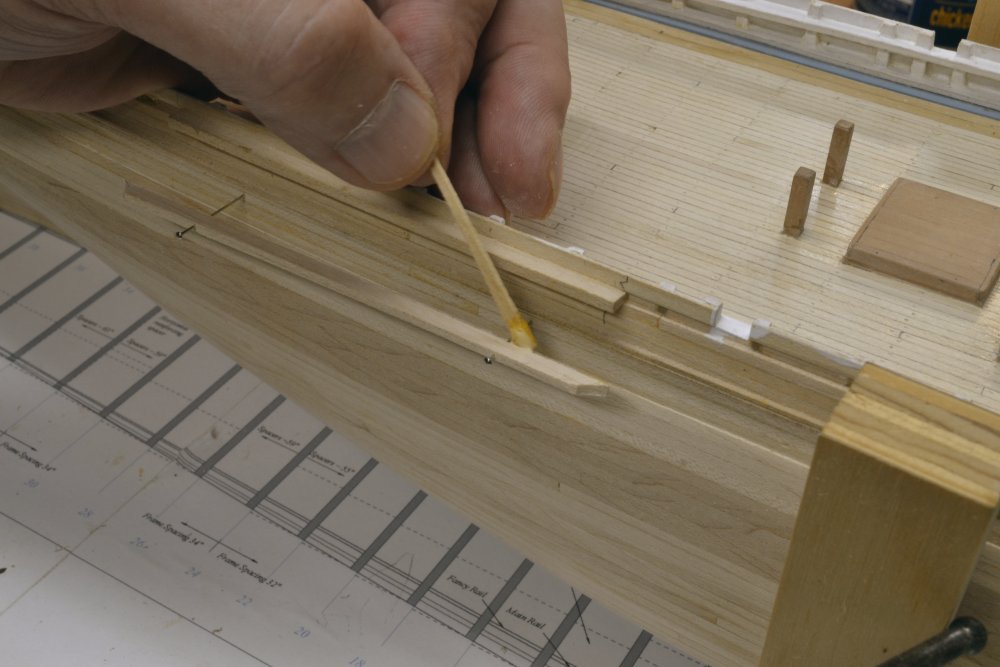
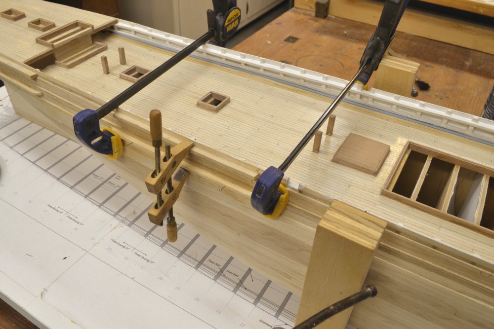
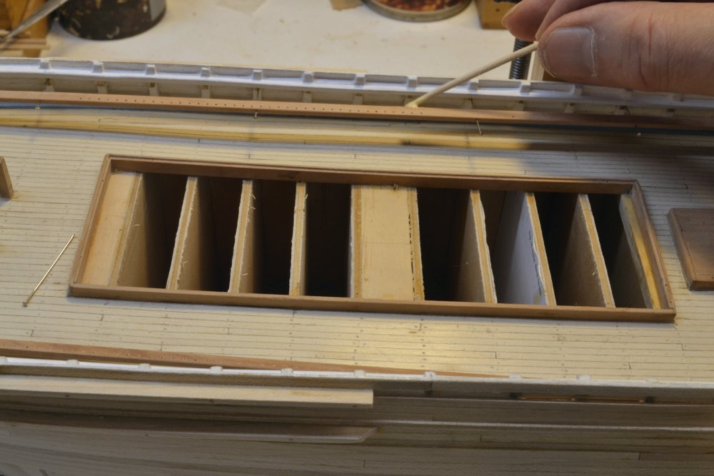
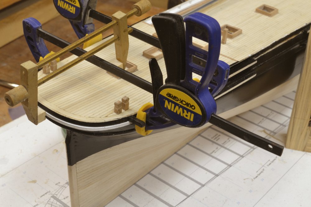
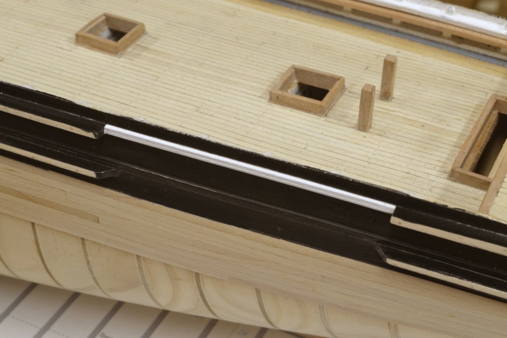
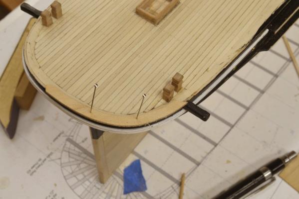
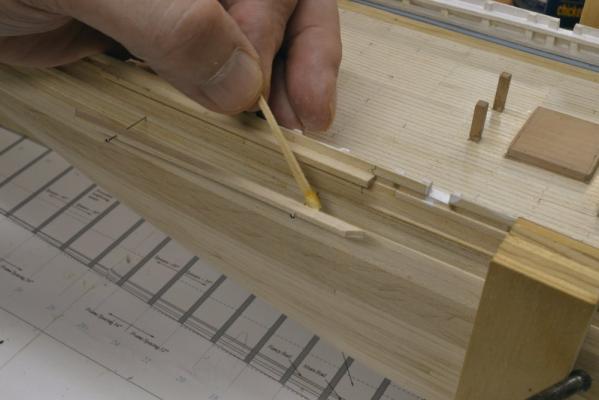
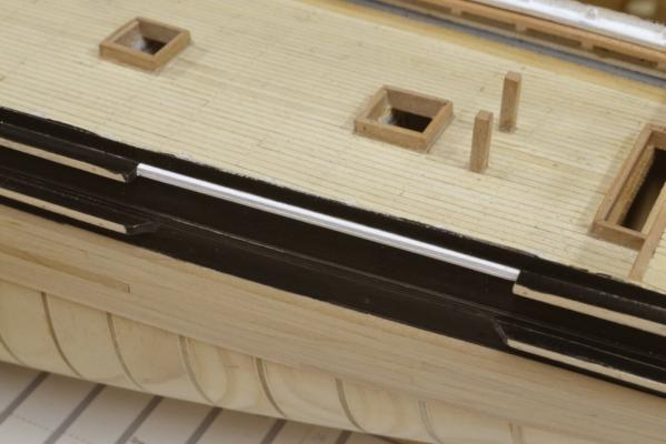
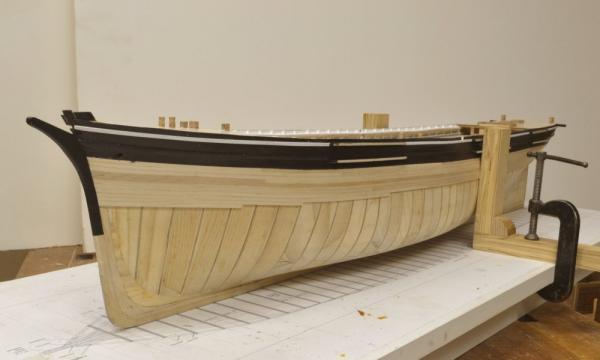
Young America 1853 – POB 1:96 Part 38 – Channels and Pin Rails The upper channels were installed first. They were glued into the gap in the outer planking left for the main rail. In the first picture these have been installed and one of the lower channels is being positioned and glued. The lower channels were first located and pinned then separated on the pins so glue could be applied as shown. The next picture shows one of these being clamped after gluing. The channel is both pinned and clamped. The small screw clamp at the center adjusts and holds the lower channel in a horizontal position. After the glue had set the pins were replaced by epoxied wire bolts to strengthen the joint. Next the pin rails inside the bulwarks were made and installed. The holes were drilled thru these on the milling machine to maintain even spacing and a smooth line. In the next picture the paint is being filed off the inside of the top timbers below the main rail so the pin rails can be glued. After the pin rail was fitted and any width adjustments made to ensure the correct projection inside the rail, it was clamped in position and holes were drilled through it into each toptimber. These were used for pins to maintain alignment when gluing and later replaced by wire bolts – epoxied in to strengthen the connection against future rigging strains. In the next picture a rail has been pulled out on the pins for application of glue. The rail was then pushed into position and clamped. With all this work completed, the hull could be painted. The methods I used for this were covered elsewhere so I will not repeat here. Once the hull and the sections of the white outer main rail were painted, those sections could be installed in the gap left in the planking. The section around the stern that was made earlier is being glued in the next picture. This piece was fitted and trimmed earlier to expose the correct width outside the planking. The next picture shows one of the installed section between channels. The last picture shows the hull on the port side at this stage. The work I planned for this model was almost complete at this stage. All that remained was to install the capping fancy rail along the top of the side. Ed


- 191 replies
-
- 33
-
-
- young america
- clipper
- (and 1 more)
-
A typo. The patterns on the right side are port timbers as evidenced by the orientation on the drawing. I will collect this with other similar minor errors and issue later in an adendum. Ed
-
Marc, I am afraid that Naiad is an unmasted hull model. I would not use the term admiralty to describe it because that type is a stylized format with simplified hull framing. Naiad is intended to replicate the structure of the ship accurately, so it details all the structural members and components based on early documentation like Steel (1805), The Shipbuilders Repository 1788 and actual ships contracts - but sorry, no masts or rigging. Substantial detailed information is available for rigging of ships of Naiad's era and type. I would recommend Steel, James Lees and others. David Antscherl describes his methods very well in Swan, Volume IV. Young America will be rigged, but the current plan is no sails. However, I am currently planning to include running rigging for all the sails except most studding sail rigging. I believe most of the gear for those sails was stored and went up when the sails were bent. My current ringing list for YA includes all the usual, plus fore and aft jib and staysail running rigging, sail handling lines like buntlines, reef tackle and leech lines, etc. So of course masts and yards will be included. Ed
-
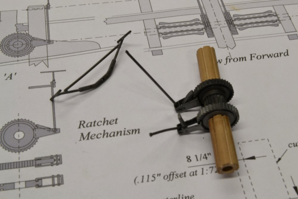
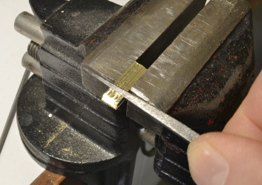
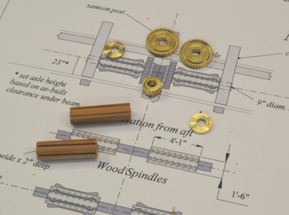
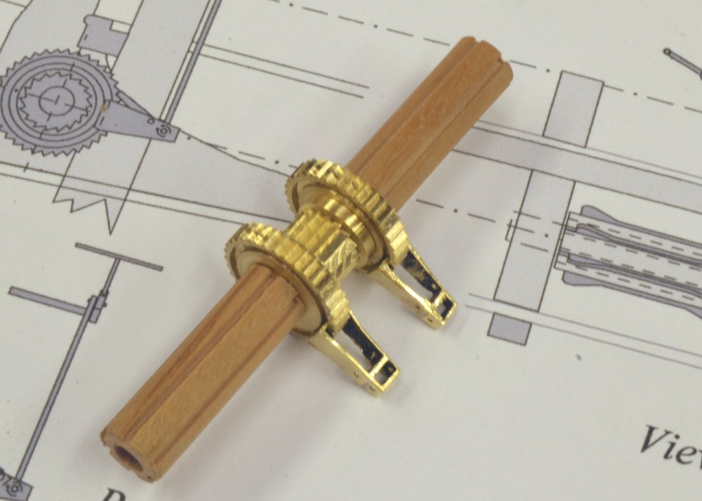
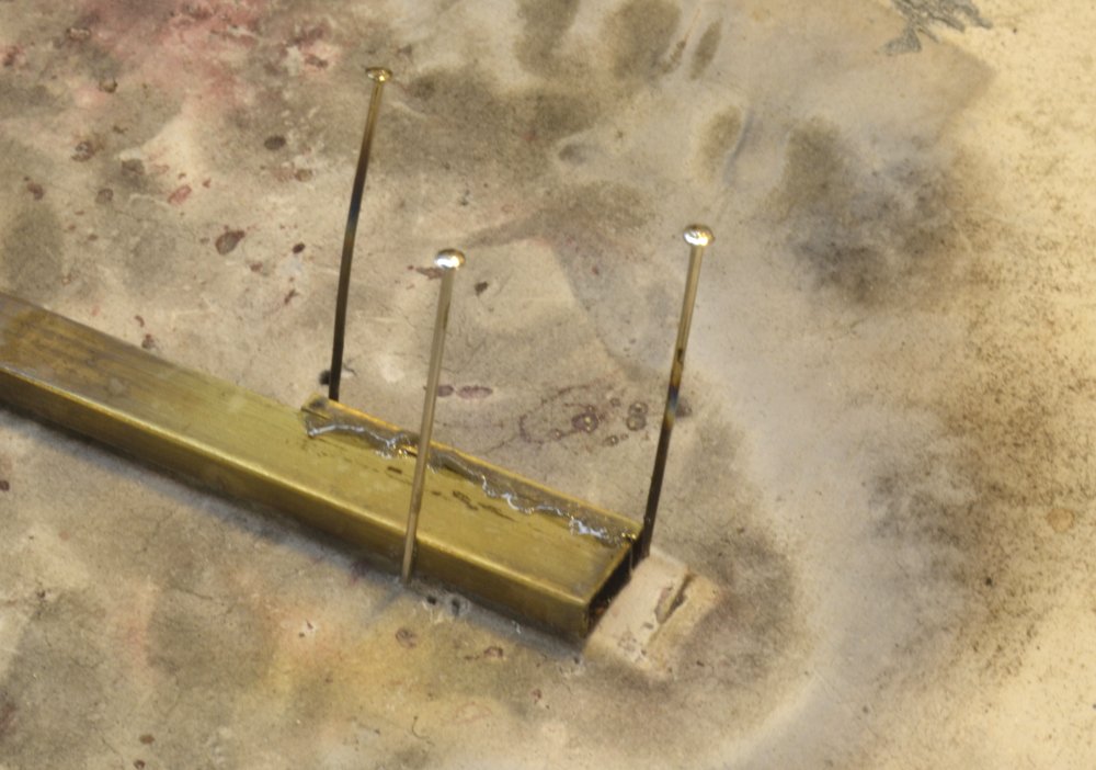
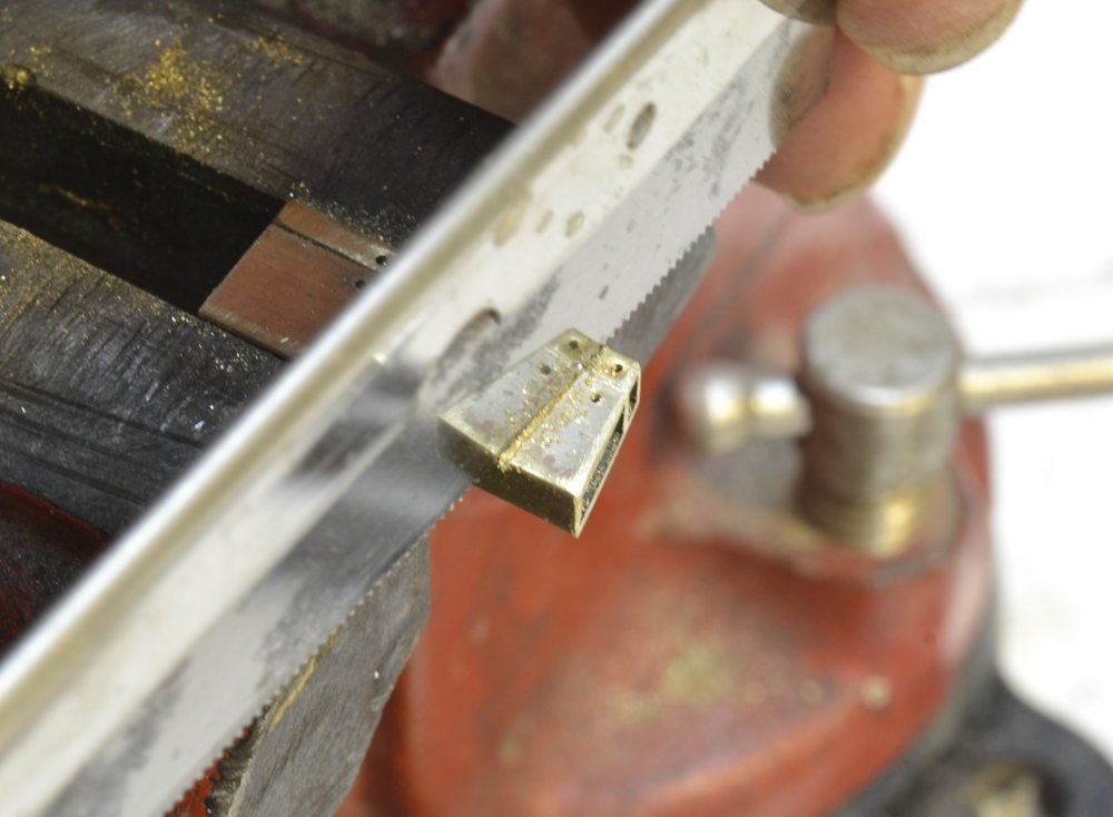
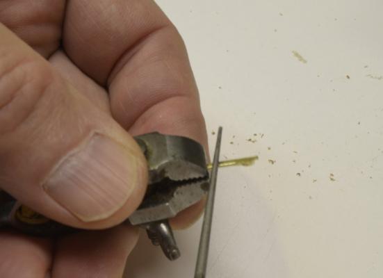
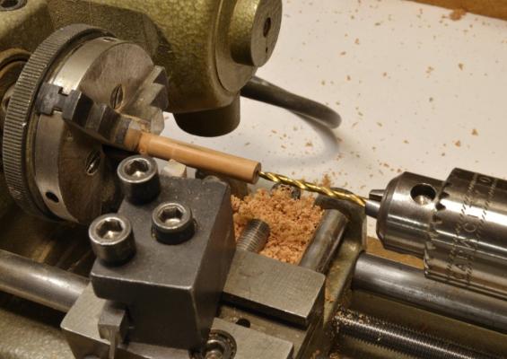
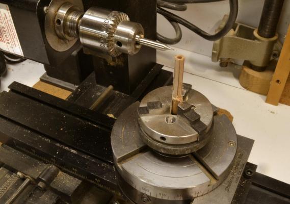
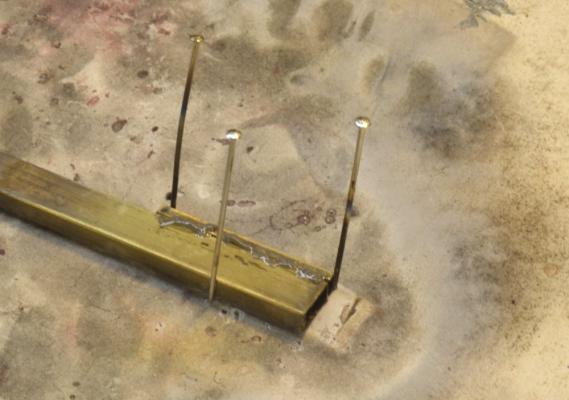
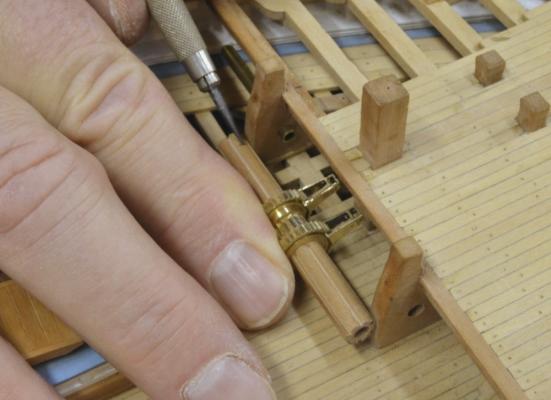
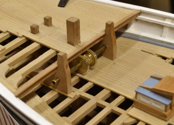
Young America - extreme clipper 1853 Part 129 – Windlass 2 After the ratchet gears, the wood spindles seemed an easy task. The first step was to turn the o.d. and bore out the center to fit the axles. The first picture shows this work completed. The wood was first turned between centers. This helped ensure centering for the axle hole. The piece was then chucked as shown, the hole drilled and the o.d. finished. The piece is long enough for both spindles. To save myself the trouble of resetting the rotating head vertical and repeating all the alignments, I decided to mill the cog slots vertically as shown below. There are six milled slots 2 ¼” deep and 2 ¼” wide – a convenient design for the 1/32” end mill. The next picture shows the two spindles cut roughly to size with the other parts made so far. These parts were then test fitted to a central shaft as shown below. Because there is not enough space for one single shaft to be inserted between the carrick bits and the side bulwarks, the shaft is made in three pieces. The rotating parts fit over a central shaft that reaches to about the midpoint of each wood spindle. Short axle stubs are then inserted from outboard of the carrick bits to hold the assembly in place. The next picture shows the assembly fitted with the frames of the two ratchet assemblies. These assemblies were made from some ¼” x 1/8” rectangular brass tube. The extended ends of the frames were made by slitting off some of the tube on the circular saw. This capping piece was then silver soldered to a full section of tube as shown below. In this picture the pieces have been pinned in place and silver solder paste applied to the joint. After soldering, holes were drilled for pins to hold the connecting rods and the ratchet stops. Then shapes of the frames were then cut off as shown below. The gear end of each of these was sliced open and fitted into the grooves on either side of the ratchet gears. In the next picture the wood spindles are being marked for final sizing to fit between the carrick bits. The sides of the ratchet frames are very close to the central samson post. To avoid contact between these parts, the two spacers between the gears needed to be replaced with slightly thicker versions to separate the large gears a bit. In the last picture this has been done and the assembly set up on the bits. The tops of the ratchet gears are very close to the underside of the breast beam – about 1”. In retrospect, I would have paid more attention to the height of the carrick bits holes relative to the deck. However, this clearance is sufficient – as is the clearance between the ratchet frames and the samson post. The next task was to position the vertical connecting rods, cut holes for them through the deck, and install the seesaw brake. Ed


- 3,618 replies
-
- 44
-
-
- young america
- clipper
- (and 1 more)
-
Thank you, Marcus. I have always thought of the modeling processes as the topic of the first books and Naiad as the vehicle - so I hope you will find the content applicable to other modeling subjects. That was the intent. This also holds true for YA, but here the ship as a unique modeling subject is more pronounced and I have developed a more personal attachment to her. While I mostly succeeded in making Young America a standalone work - not dependent on the Naiad books - this was not always possible due to space limitations and some desire to avoid repetitions. Who wants top pay for the same process content twice? The ships are also quite different and so are some of the modeling methods. Our desire to pack all of the Young America work - which will include rigging - into two volumes, has been and will continue to be a challenge. Thanks for your interest in the books. I am sure Bob Friedman will readily accommodate you. Ed
-
Addendum 2 A revised 1 to 72 Sternpost-Deadwood Pattern Sheet is attached. On the original version (Chapter 3 folder on the CD) the inner post and the top section of deadwood were shown incorrectly. 1to72 Sternpost-Deadwood Patterns.pdf Ed
-
A corrected Sternpost-Deadwood Pattern Sheet is attached. 1to72 Sternpost-Deadwood Patterns.pdf Ed
- 3,618 replies
-
- 3
-
-
- young america
- clipper
- (and 1 more)
-
Thanks, again, everyone. Bob, again I appreciate your pointing out this problem and regret that my checking did not pick all this up. There is certainly an inconsistency in the pattern sheet. The template is correct. I initially intended to keep the deadwood below the middle deck, buteventually decided to bring it up through the deck as is shown the template and the large printed elevation drawings. As with the inner post, I then failed to update the pattern for the top piece of the deadwood on the pattern sheet.. In a quick review of the drawings and the full set of photos taken during the period of interest, I well remember uncertainties I felt about the heights of the deadwood and the inner post. In fact, you may see in some of the photos that my original inner post was too short and had to be lengthened. Work on the drawings and the model was an iterative process in some areas areas. An easy immediate solution would be to make the top aft section of deadwood from a pattern cut from the template. I will post a corrected pattern sheet, shortly - here and on the book topic. Ed
- 3,618 replies
-
- 3
-
-
- young america
- clipper
- (and 1 more)
-
I really appreciate all these comments and likes. I will try to get the remaining parts on the windlass out quickly. I think I may need to do some woodwork before attacking the next metalwork job - the bilge pumps. Ed
- 3,618 replies
-
- 7
-
-
- young america
- clipper
- (and 1 more)
-
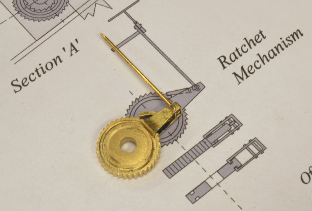
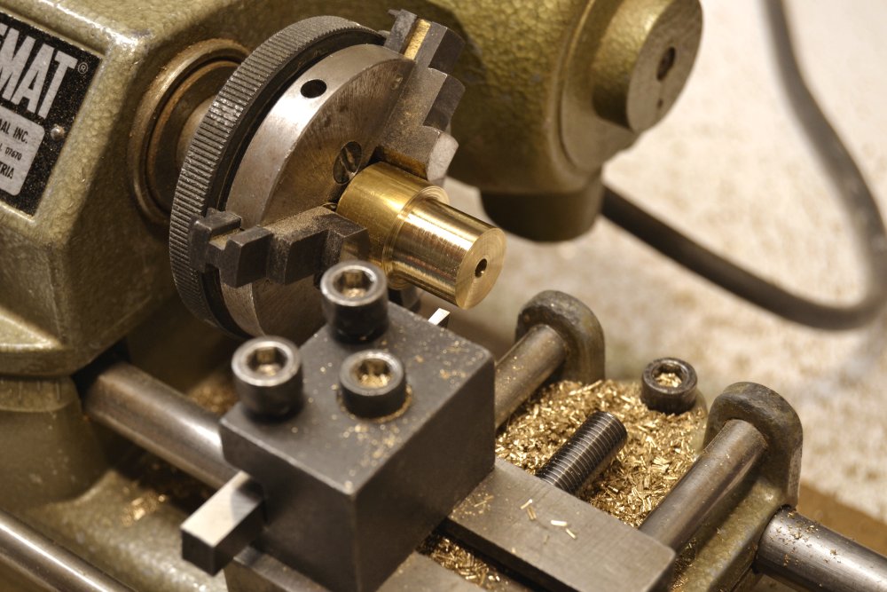
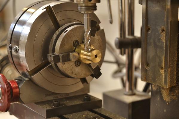
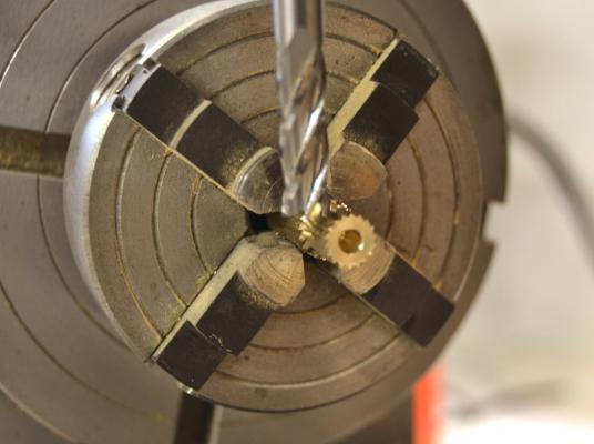
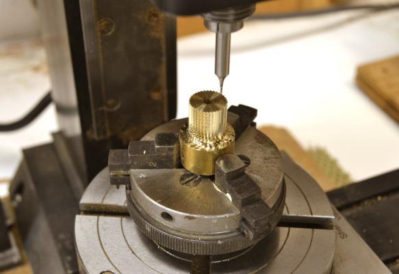
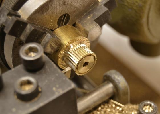
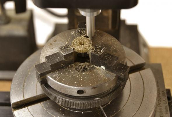
Young America - extreme clipper 1853 Part 128 – Windlass 1 For some time I have been anticipating (or perhaps dreading) making and fitting the windlass that was used to raise and secure Young America’s anchors. Like many of the model’s details, the windlass is one that was typical of the time. It is a fairly complex piece of equipment with a variety of mechanical parts. Not everyone will be familiar with this device, so I will start with a picture and description of the assembled windlass and then work through its construction. The assembly shown is still only pinned together temporarily. The windlass axle was supported by the two stout “carrick bitts” on either side. The large, central “samson post” supported the seesaw brake lever assembly and also the anti-backlash stop shown engaged on the central ratchet gear. The anchor chain was wrapped around one of the wood spindles on either side of the central ratchet parts. These spindles were fitted with iron cogs to engage the chain links. The spindles were turned from the forecastle deck by means of the seesaw brake. This was connected to two ratchet mechanisms that engaged each of the two large ratchet gears – turning the gear on the up stroke and ratcheting back on the down stroke. These ratchet mechanisms are not visible in the picture, but one is shown in the next picture. I had considered the possibility of making this a working model – until I printed off the first copy of the scale1:72 drawing. A working model could be made from the drawings but not at this scale by me. I am sorry to say that this lovely little bracket mechanism is virtually invisible below the forecastle – a persistent dilemma for below-deck details. The operating principle can be seen in the picture and drawing. The connecting rod that passes vertically up through the deck pulls or pushes on a bracket that is fitted with bar that is pinned through the bracket, allowing it rotate out of the gear teeth on the down stroke, but engage on the up stroke. The bracket rides in grooves on each side of the gear wheel. Before dropping anchor, the required length of chain was hauled manually – the windlass worked in only one direction - up through the chain tubes, along the deck forward, across the top of one of the spindles, around the spindle, then laid on the main deck forward under the forecastle until relased I decided to start construction with the two large (36”, 1/2” actual) ratchet gears. The first step is shown below. In this picture some ¾” brass bar is fixed in a self-centering 3-jaw chuck in the Unimat lathe. It has been center-drilled for the 9” (1/8”) diameter shaft, faced off square on the end and turned to the 36” gear diameter – enough to make two gears. The chuck and the piece were then removed without disturbing the centering to a rotating head on the milling machine as shown in the next picture . After carefully centering and aligning the setup, the cutter was set to mill the 36 evenly spaced ratchet gear teeth. The teeth have 90 degree points that are offset – angled to one side so the ratchet bar will engage tangentially. To do this one side of the cutter was moved off-center based on a digital measurement on the CAD drawing then lowered by another measured amount. Each of the 36 teeth was then cut by stepping around the piece in 10 degree increments. The central stop ratchet was cut by the same method – with different settings – at 20 degree increments to yield an 18 tooth gear – as shown below. The next photo shows the mill setup for cutting the groove in one side of the first ratchet gear. A 1/32” square end mil was used to cut the 2” depth in two passes. After this the chuck was returned to the lathe for parting off of the gear as shown below. The piece was then returned to the mill to cut the groove in the second gear. The parted off gears were then chucked on the mill to cut the grooves on the other side – in progress in the next picture. Simple spacers were also made to fit between the gears. All these parts are shown set up on a temporary axle in the last picture. With the aid of precise dimensional adjustments from the CAD drawing, making these was less difficult than I expected. I did reject the first two gears, for - of all things - mis-centered axle holes. There is no doubt that accurate centering for all this work requires care. It is made simpler by keeping the piece chucked as long as possible. For this reason the Unimat chuck was also used in the Sherline mill without removing the parts – once the mill setup was aligned. Making the spindles and brackets will be described next in Part 129. Ed


- 3,618 replies
-
- 39
-
-
- young america
- clipper
- (and 1 more)
-
Thanks, Remco, but I don't know - nerve or lack of imagination? I just couldn't imagine me doing this before installing the margin planks, at least not at 1:96 - probably not at even at 1:48. Actually, marking out and cutting into the margin in place is quite easily done and with a bit more care the results could undoubtedly be much improved. Ed
- 191 replies
-
- 5
-
-
- young america
- clipper
- (and 1 more)
-
Hello Marcus. I am glad the Naiad build still attracts some attention. It was a challenging and educational project for me from start to finish - including doing the books. At the risk of pushing book sales, all of the questions you raised - and many others are addressed in the books, but I will try to give you some short answers: Bolts: I tried to simulate the actual fastenings that were used, based on various sources including contracts for similar RN ships built at the time. These are available for many ships from NMM. Treenails (on the model bamboo - on the real ships oak ) were used mainly for planking on these ships. Structural fastenings were bolts of copper (below water) and iron. These bolts were more like long nails or in many cases long rivets. They were driven through undersized holes and often peened over at both ends. Some of these (in the deadwood for example, might be 15 feet long. Deck planking was very likely held by iron spikes covered with wood plugs. Copper bolts on the model are copper wire, untreated. Iron bolts are also copper wire but blackened using Liver of Sulfur solution - usually after insertion. Details of the magazine came from a number of sources - drafts for overall arrangement and placement, contracts and some secondary sources for details. The magazine is completely detailed on the model (though unfortunately not visible) and full details are shown on drawings in the book (Volume II). The miniature screw clamps were homemade. Details and dimensioned drawings for making the "Jorgensen" type plus a simpler version as well as other tools are included in the book (Vol I, Appendix II). Appendix I in Volume I describes how the drawings and patterns were developed in 2D CAD based on Admiralty drafts and scantlings - using older software before I moved to TurboCad - but descriptions would apply to both - or other programs. Again, thanks for your interest - and questions, of course. Ed