EdT
-
Posts
2,214 -
Joined
-
Last visited
Content Type
Profiles
Forums
Gallery
Events
Everything posted by EdT
-
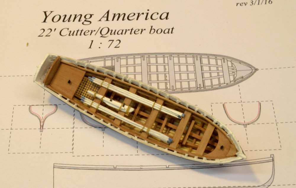
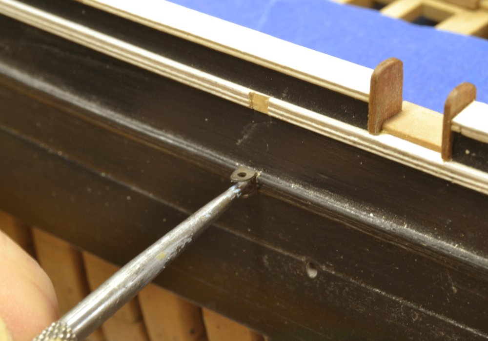
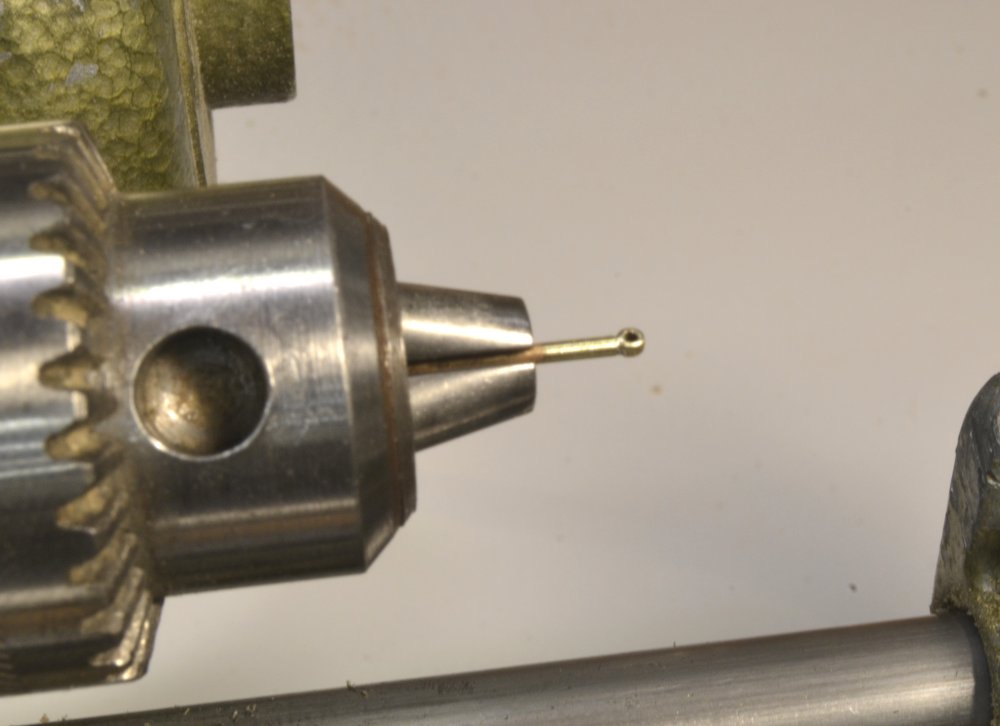
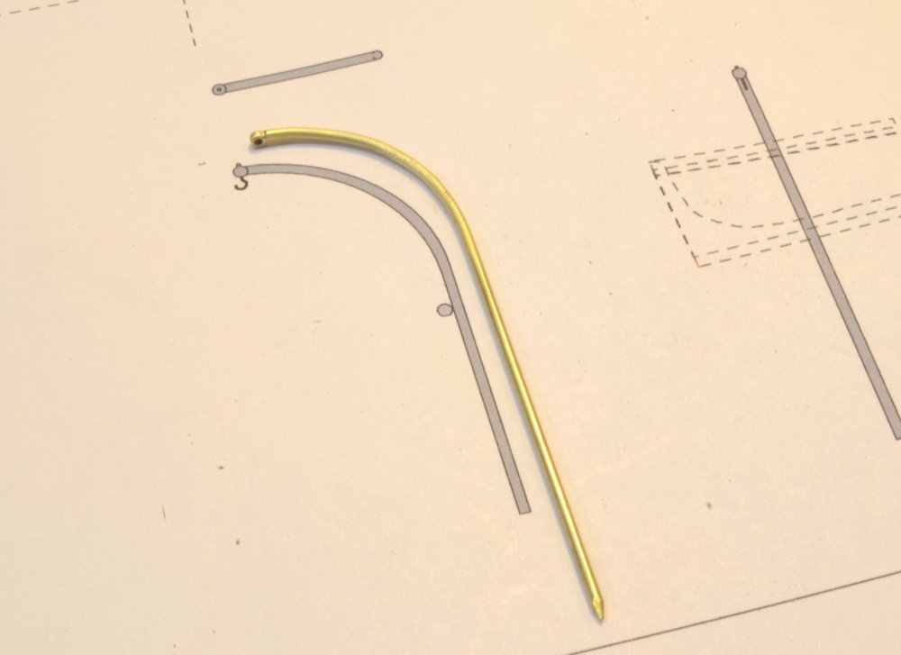
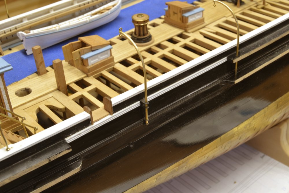
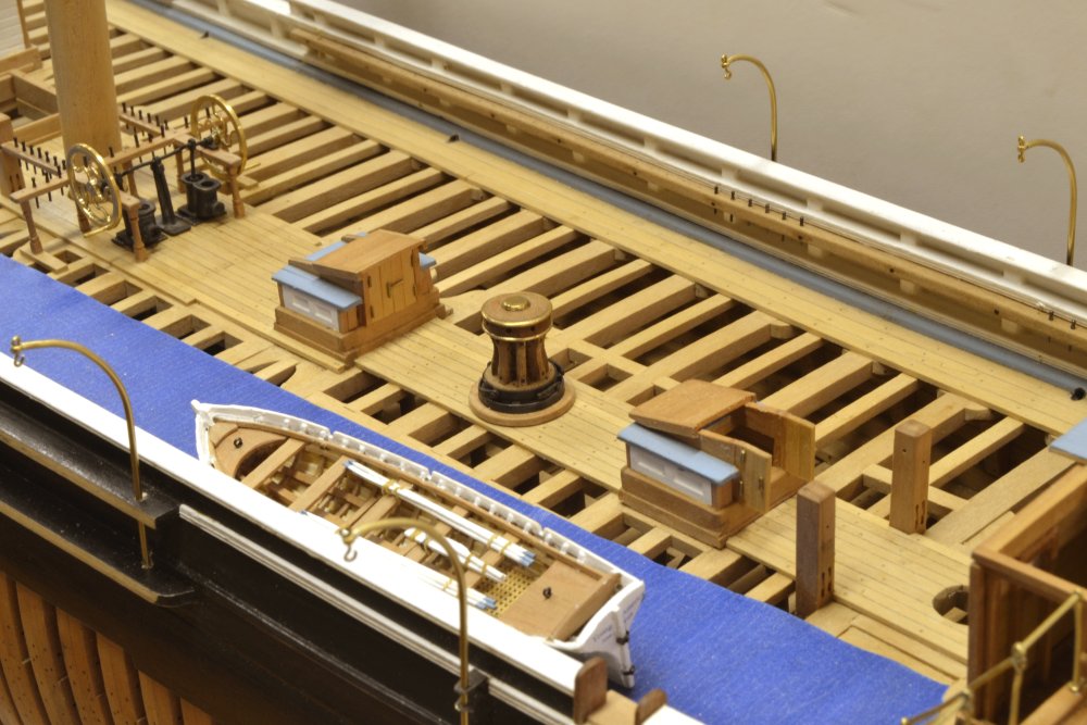
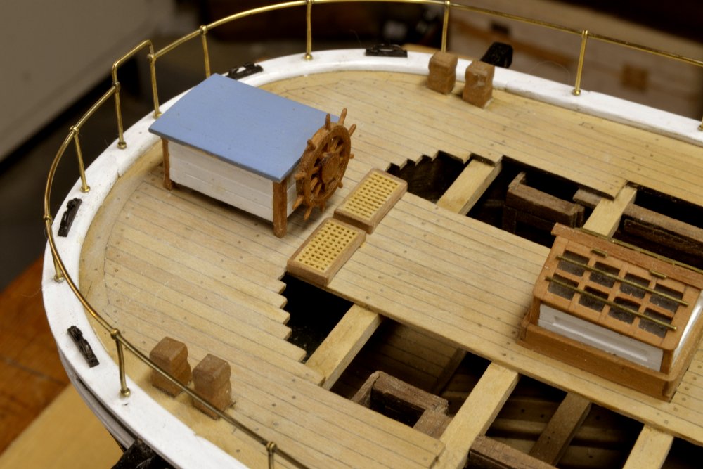
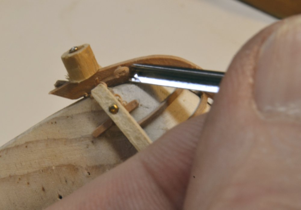
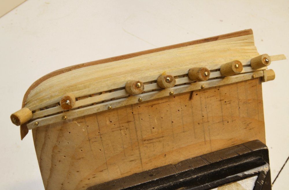
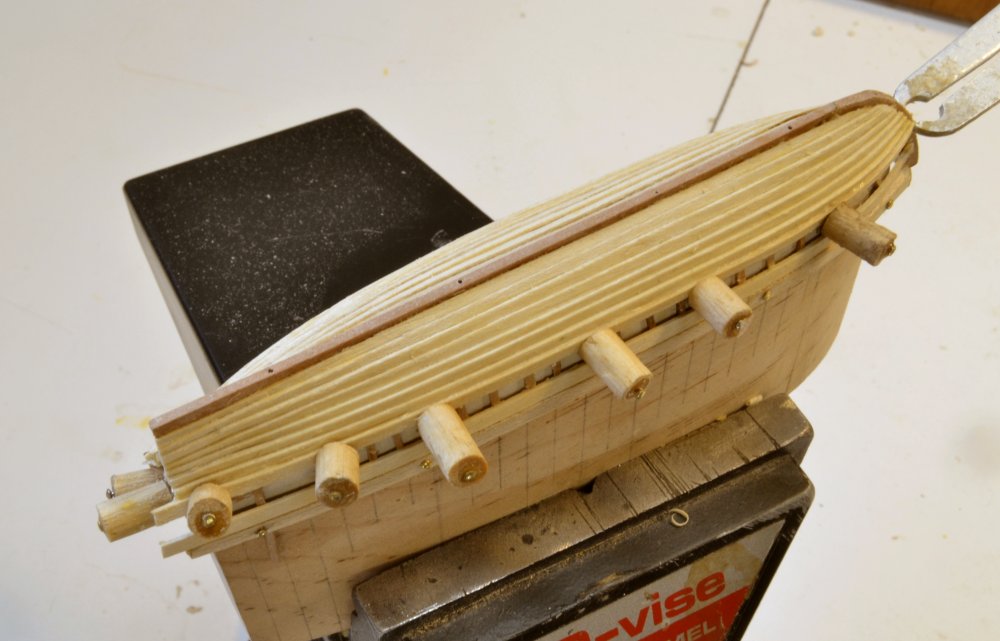
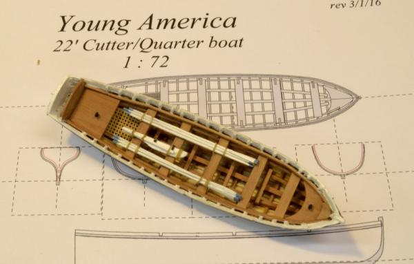
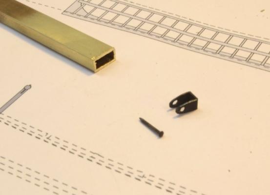
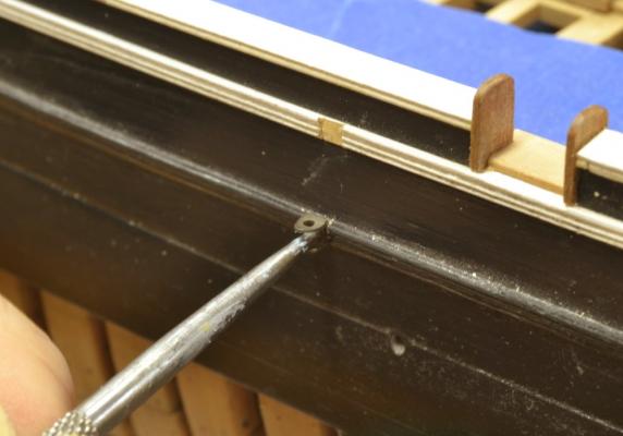
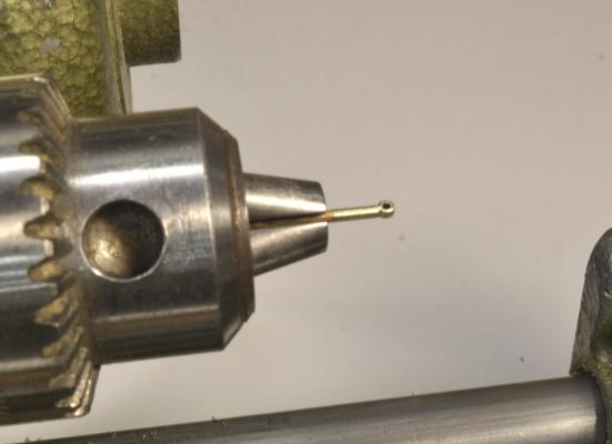
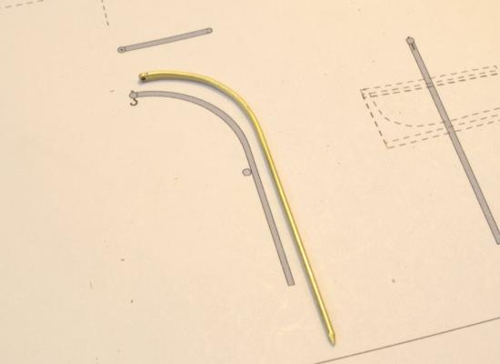
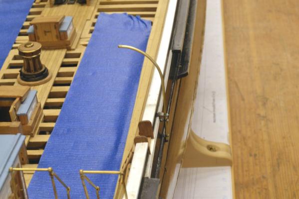
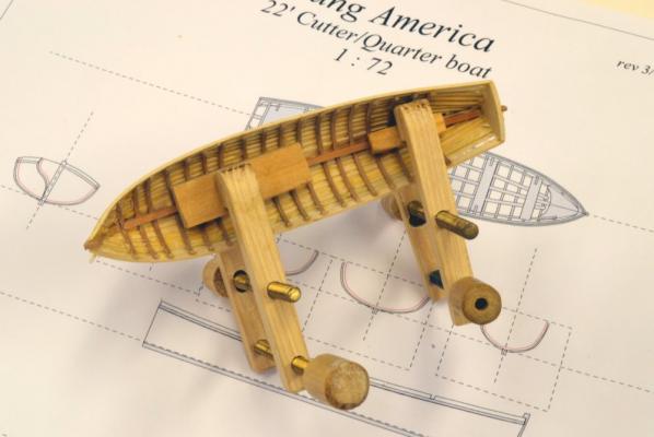
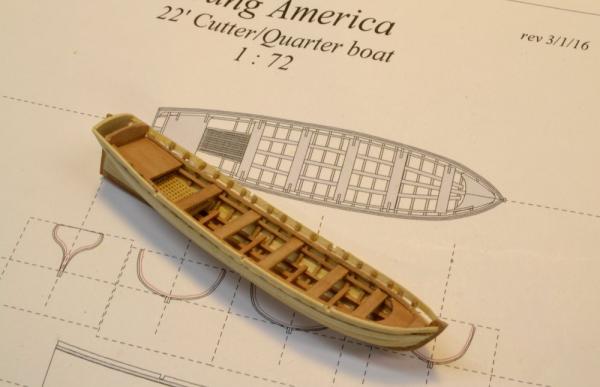
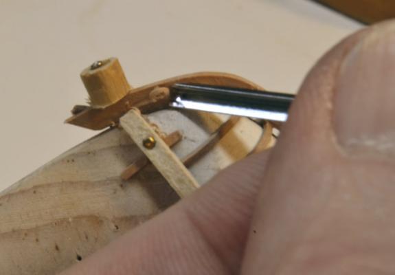
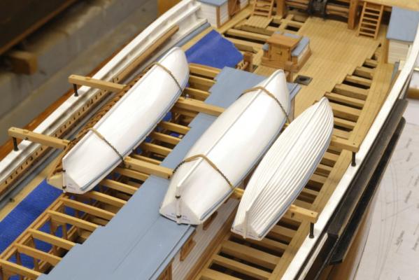
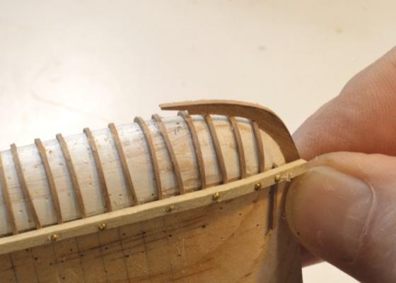
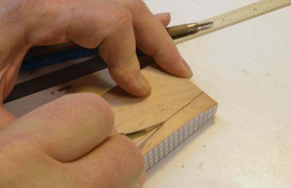
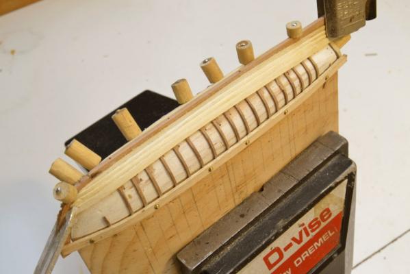
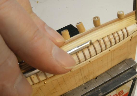
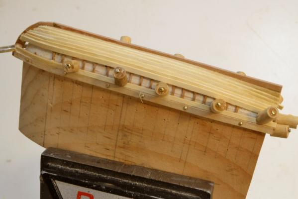
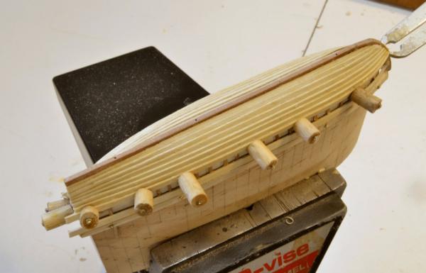
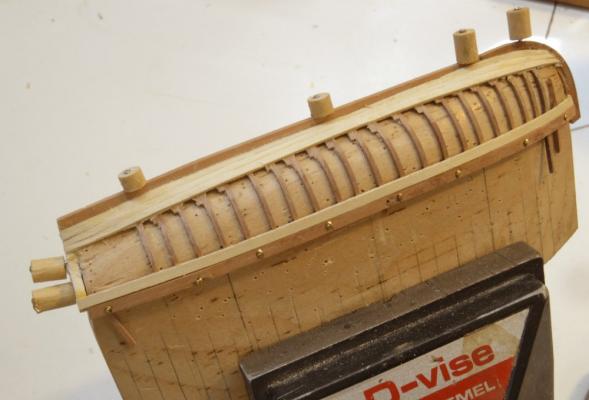
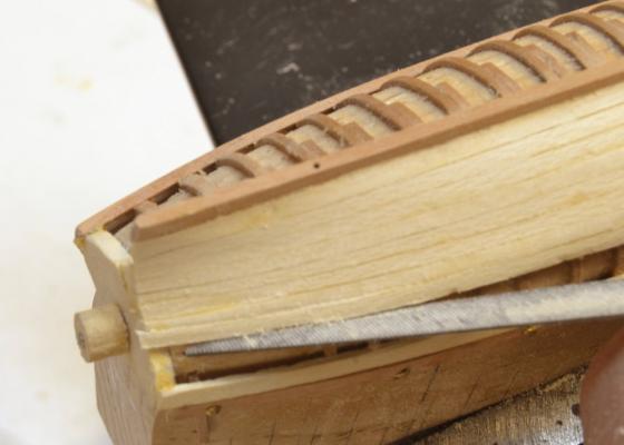
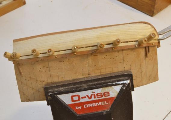
Young America - extreme clipper 1853 Part 154 – Quarter Davits It seems like a while since the last post. Progress has been slowed by research, documentation and drafting for the rigging. However, about a week ago the last of the four boats was completed and since then the quarter davits have been made and fitted. The first picture shows the completed 22’ cutter that will be secured to the starboard davits. The 6 sweeps were made from drawn bamboo flattened at one end. The quarter davits were secured outside the hull just aft of the main channels. The forward davits were supported by the channels. The aft pair were held by iron brackets. One of these and its bolt is shown in the next picture. This is a top bracket – longer to account for the inward slope of the sides. The lower brackets are shorter with a hole only in the top. All were made from the brass rectangular section shown in the picture. In the next picture a lower bracket is being installed. The rails were mortised to fit these. The next picture shows the top end of one of the davits in the lathe after cleanup of the solder and rounding of the top bearing. The ends were fashioned by the method used for the poop handrail stanchions. The next picture shows one of these shaped. After cutting to size, this davit was fitted as shown in the next picture. The next picture shows both starboard davits fitted with their hooks installed. The last picture shows all four davits. These will probably be blackened to simulate iron, but I have not decided. They appear black in one of the photos. I will probably put these into storage with the boat until later. There is quite a bit of rigging to be installed along the rails that will best be done with maximum access. The above picture shows a break in the belaying pins that extends almost the length of the boats. Pins forward of the six at the forward end of the space will extend uninterrupted all the way to the cargo opening and virtually all will be used. There were a lot of sails on one of these ships. A half dozen square sails per mast, an equal number of studding sails on the forward masts, plus quite a few fore and aft sails. While I do not intend to install sails, I do plan to install most of their rigging, excluding most of the studding sail rigging and other items like staysail sheets. I expect access to be an issue. Ed


- 3,618 replies
-
- 39
-

-
- young america
- clipper
- (and 1 more)
-
Addendum 3 to Volume I This addendum addresses a number of inconsistencies between sidings shown on frame patterns and sidings specified on the List of Dimensions. As a general rule, the List of Dimensions should be considered the governing source for dimensional data and should be consulted before sizing any pieces. For convenience, siding dimensions were shown on the patterns. Placing dimensional data in more than one place is bad practice and usually results in inconsistencies, as it did with a number frame patterns. These inconsistencies and a few other minor issues have been corrected and revised patterns are attached. Patterns not included in the attached need no correction. The sidings for cant and half frames given in the List of Dimensions are generalized. The specific sizes for each of these frames can be taken correctly from the patterns. In virtually all cases, the corrected sidings differ from those on the original patterns by 1 or sometimes 2 inches (.014” to .028” actual). In most cases the pattern differences resulted from transitions to the reduced sizes at the ends of the hull, being taken at different stations than specified on the List of Dimensions. Since decisions on where to place these transitions was somewhat arbitrary, since size differences are small, and considering that most of the upper futtocks will be covered by outer planking, some may consider these corrections somewhat academic. However, this should not be license for inconsistencies in the information. I for one, consider precision to be important and regret these errors in the original package. All the addenda will be included on the CD in the next volume. An updated pattern sheet for the bow timbers is also attached. The original labeled both sides stbd. Ed 1to72 Bow Timbers Patterns.pdf 2f.pdf 17a.pdf 17f.pdf 18a.pdf 19a.pdf 20a.pdf 21a.pdf 22a.pdf 23a.pdf 24a.pdf 25a.pdf 26a.pdf 27a.pdf 27f.pdf 28a.pdf Aa.pdf Af.pdf Ba.pdf Bf.pdf Ca.pdf Da.pdf Ea.pdf Ef.pdf Fa.pdf Ff.pdf Ga.pdf Gf.pdf Ha.pdf Hf.pdf Ja.pdf Ra.pdf Rf.pdf Sa.pdf Sf.pdf Ta.pdf Tf.pdf Uf.pdf
-
Nice work so far, Tom. I too like to see some bread and butter work enter the fray. I found the Microplane to be a very good tool for hull shaping, leaving little dust and able to shape a softwood quickly hull right up to the 120-grit hand sanding stage. A little late for you at this stage, but maybe for later. Ed
-
Thank you, all. I will be glad to get on to something different - different, that is, from making boats and belaying pins. Ed
- 3,618 replies
-
- 4
-
-
- young america
- clipper
- (and 1 more)
-
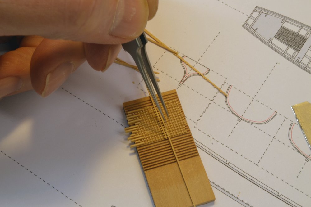
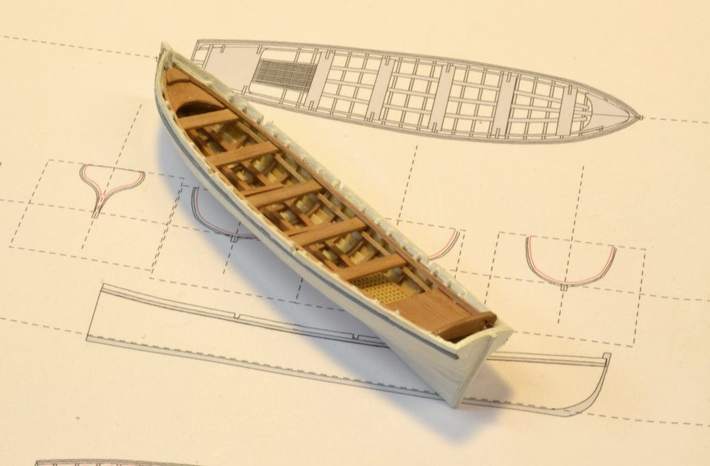
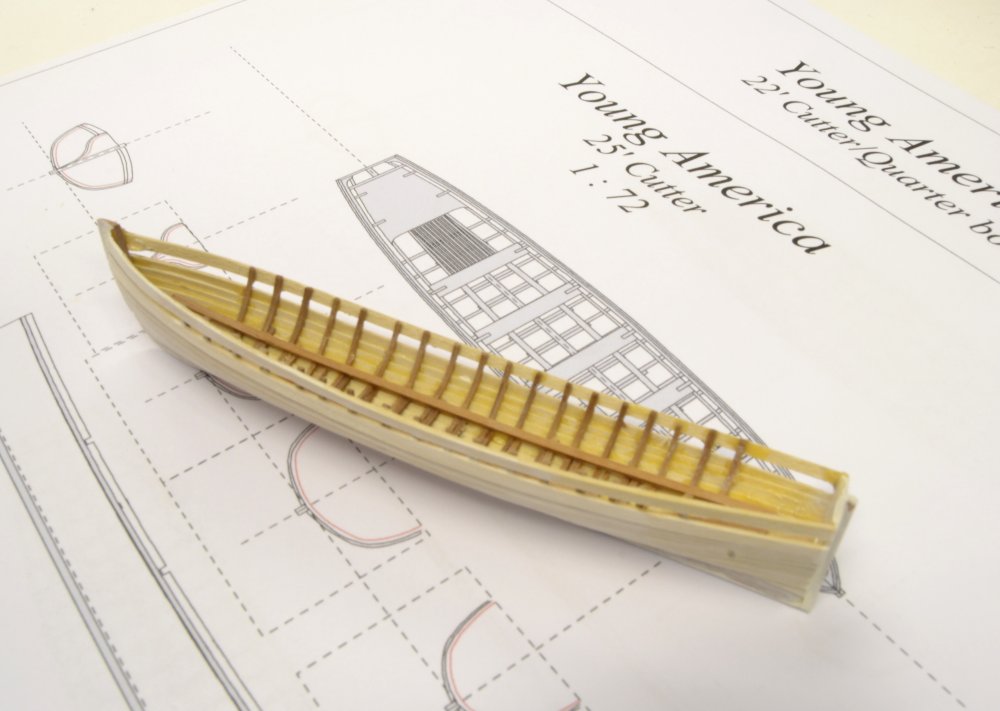
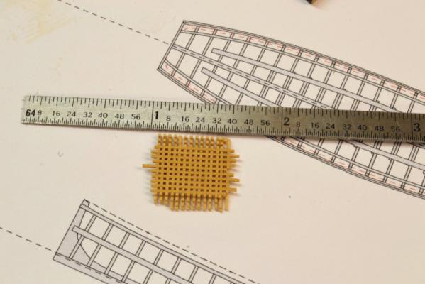
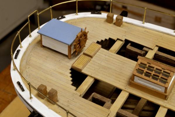
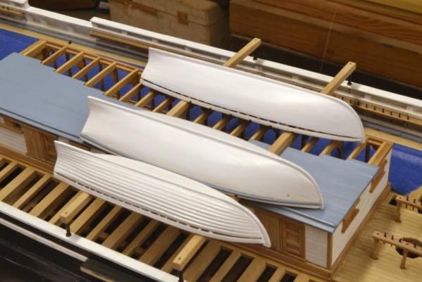
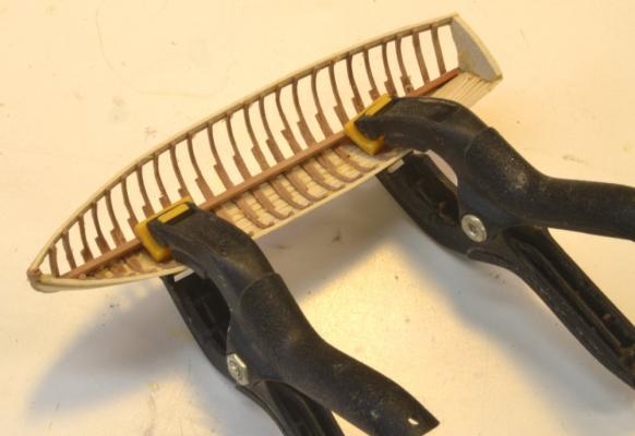
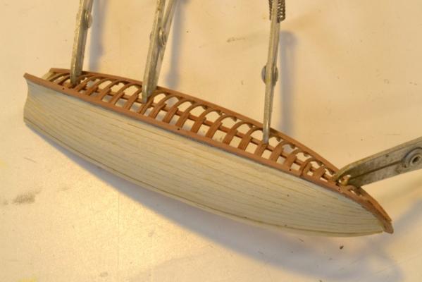
Young America - extreme clipper 1853 Part 153 – Ship’s Boats 9 Well, time is passing quickly and work on YA’s small boats has been going slowly – much too slowly for someone with my temperament, but the end is in sight. I am sure that many, like me, will be glad to something new after all these small boat pictures. This post should just about do it. In the first picture, the last of the small boats, the 22’ cutter that will later hang from quarter davits, is getting its keelson installed. Since this boat will be hung upright, the internals will be visible. In the next picture some grating that will be used for a floor under the stern seats is being assembled on a spacing template. The members of this grating are less than 1½” wide (.020”) on <3” spacing, made from Castelo. The assembled section is shown below, before sizing and framing. The grating was made, for the most part, as shown in earlier posts, or perhaps in Naiad posts, using the milling machine for precision and in this case to slit the milled strips without damage. The grated flooring can be seen in the next picture where one of the thwarts is being installed. In the next picture the boat is ready for painting. The missing wales will be added after both they and the hull are painted. The next picture shows the almost completed boat. All that remains is to add the lettering, the oars, the rudder and some iron hardware. I have not been happy with the grated platforms at the helm, seen in earlier posts, so I took the opportunity to replace them with some grating of the smaller size, as shown in the last picture . Ed


- 3,618 replies
-
- 45
-
-
- young america
- clipper
- (and 1 more)
-
I believe the main purpose of the burton pendants was to put tension on shrouds and backstay - mainly lower shrouds. A tackle could be attached to these and the shroud laniards and used to tighten the shrouds when initially fitted and later as needed. See plate 177 in Darcy Levers's Young Sea Officers Sheet Anchor (1819) for example. These were called pendant tackles on 19th century American Ships and served the same purpose until rigging screws came into use. See S.B.Luce, Seamanship (1868) Figure 46 for example Ed
-
Thank you for posting those pictures, Nils. Beautiful. Rd
- 2,625 replies
-
- 4
-
-
- kaiser wilhelm der grosse
- passenger steamer
- (and 1 more)
-
Hello Nils, I have fallen behind in keeping up with your progress but I have caught up and am most impresses. The winches look great as does the other deck detail. I would love to see a picture of the whole model at its present state. Congratulations on a beautiful model. Ed
- 2,625 replies
-
- 4
-
-
- kaiser wilhelm der grosse
- passenger steamer
- (and 1 more)
-
Absolutely beautiful work, Alexandru. Ed
-
Hi Gary, Lovely work so far. I am not sure what you meant by the shape being a little sharp at the bow, but I think you will find that correcting any misalignment will be much easier now than later - but you may be able to judge that best based on your measurements. I did a lot of frame adjustment to correct setting errors. Simply break the joints with the softwood chocks and re-glue them after the adjustment. The best way to avoid this type of problem is to consistently check positions by squaring up from lines on the base plan as each frame is added. This can be a challenge on the forward frames, especially if left over length, because the height of breadth lines normally used for this fall inside the top of frame line at the bow. Marking the height of breath lines on the patterns and using those may help - or square up the the top of frame line on the still-attached patterns. Do not use the actual tops of over length frames. This persistent checking is easy to neglect in the desire to get on with setting frames, but it is the best way to maintain confidence that all is well. Unfortunately, the eye alone is usually deceiving. However, all that said, your work is looking fantastic. Ed
-
Effie M Morrissey by allanyed
EdT replied to allanyed's topic in - Build logs for subjects built 1851 - 1900
Nice work, Allan. Good to see you back. Ed -
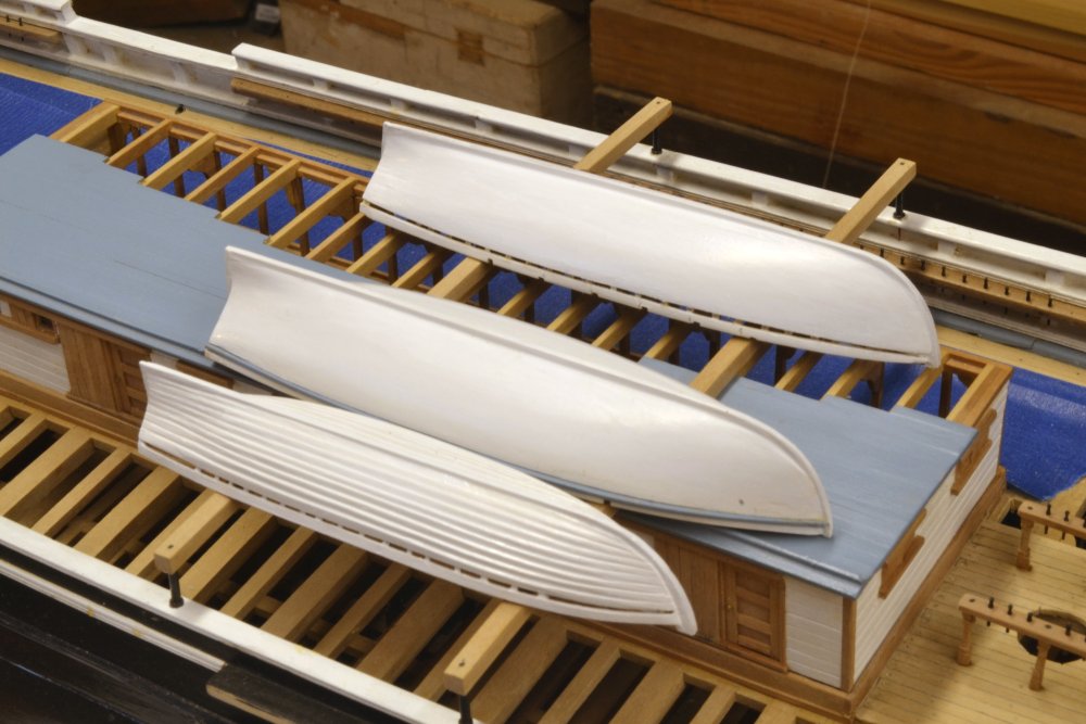
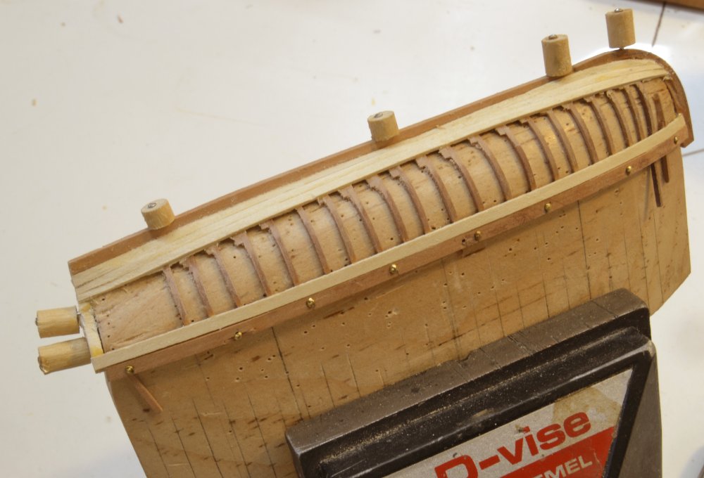
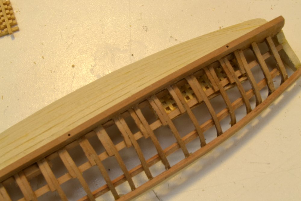
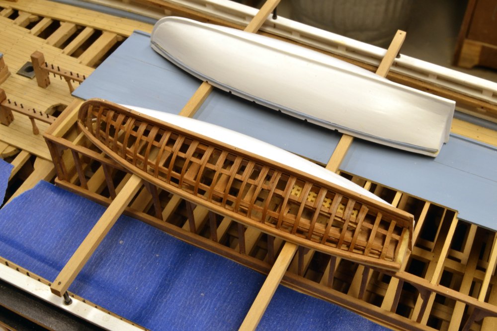
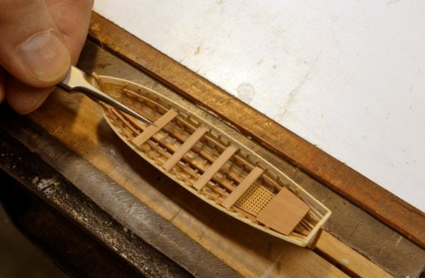
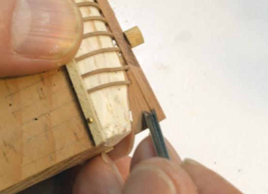
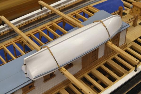
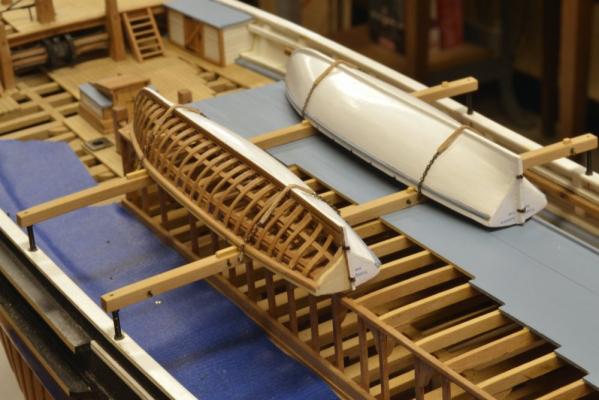
Young America - extreme clipper 1853 Part 152 – Ship’s Boats 8 I am almost there with the boats and looking forward to getting on with something different. In the last part the frames and keel assembly for the 22’ cutter were fitted to the plug. This boat will hang from quarter davits on the finished model. In the first picture the rabbet if the stem is being roughed out with a V-gouge. In the next picture the rabbet is being pared out at the stern. This was followed by some filing and cutting of the rabbet along the keel. The starboard garboard strake is being installed in the next picture. Additional planking has been installed in the next picture and the last installed strake is being beveled at the stern. The angle of the bevel becomes more perpendicular to the side at the ends of the boat to allow the lapstraked planking to blend flush at both ends. The planks also need to be tapered to fit fairly and come out right at the top. In the next picture the planking is complete except the the wale strake that will be fitted after painting. After some cleanup and dressing the planking lines, the boat will be removed from the plug for internal work and finishing. In the meantime the other boats have been completed and one of the longboats is shown chained down to the skid beams in the next picture. The chains have been fitted with covering to protect the boats. One end of the chain is hooked to an eyebolt and the other is lashed to another eyebolt on the other side. In the next picture the boat on the port side has been secured and wood chocks have been installed on the beams to restrain movement of the boats. The last picture shows the 25’ cutter temporarily in place and complete except for the rudder hinges. This boat will be held in storage and secured later after rigging is belayed between it and the rail. Ed


- 3,618 replies
-
- 45
-
-
- young america
- clipper
- (and 1 more)
-
Hello Bob, The siding references are correct. Webb reduced weight at the ends of the hull by increasing frame separation and reducing the size of framing timbers at the ends of the hull. On the patterns I reduced the sidings from frame U forward and from Frame 19 aft. The exact locations of these transitions could be argued, but this was the basis I used for the patterns. The forward reductions could have actually been started a few frames aft, but I eventually settled on U. You will also note that half and cant frames are similarly reduced in siding. The changes in frame separation are noted on the shipway plan drawing. Webb was a bit more innovative than most other builders in designing to resist hogging of the hull. Whereas more typical designs utilized additional wood mass (sister or multi tiered keelsons for example) to provide strength, Webb reduced structural weight at the ends by reducing timber sizes. It is said that by this method about 25 tons could be removed, thus reducing the stress that caused deflection in these areas of decreased buoyancy caused narrowness of the clipper hulls. Not that Webb skimped on timber as with the huge keelson and heavy ceiling members - also the iron strapping. He originated the use of iron strapping on American ships with Challenge in 1851. I believe this was discussed in Chapter 1. I take the terms lower futtocks and first futtocks to be synonymous, but consistent usage would have been better. Ed
-
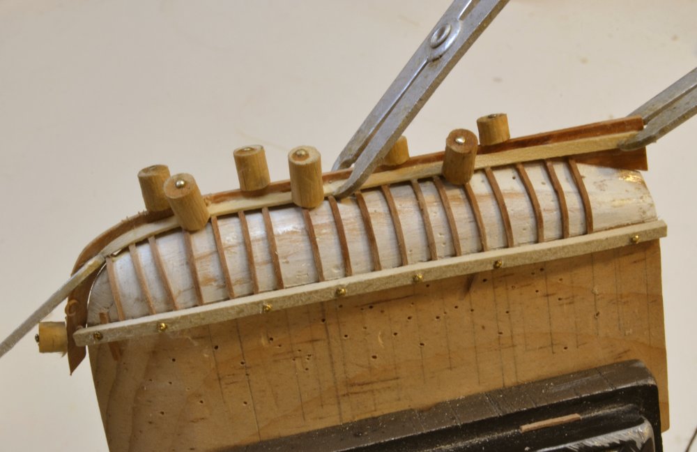
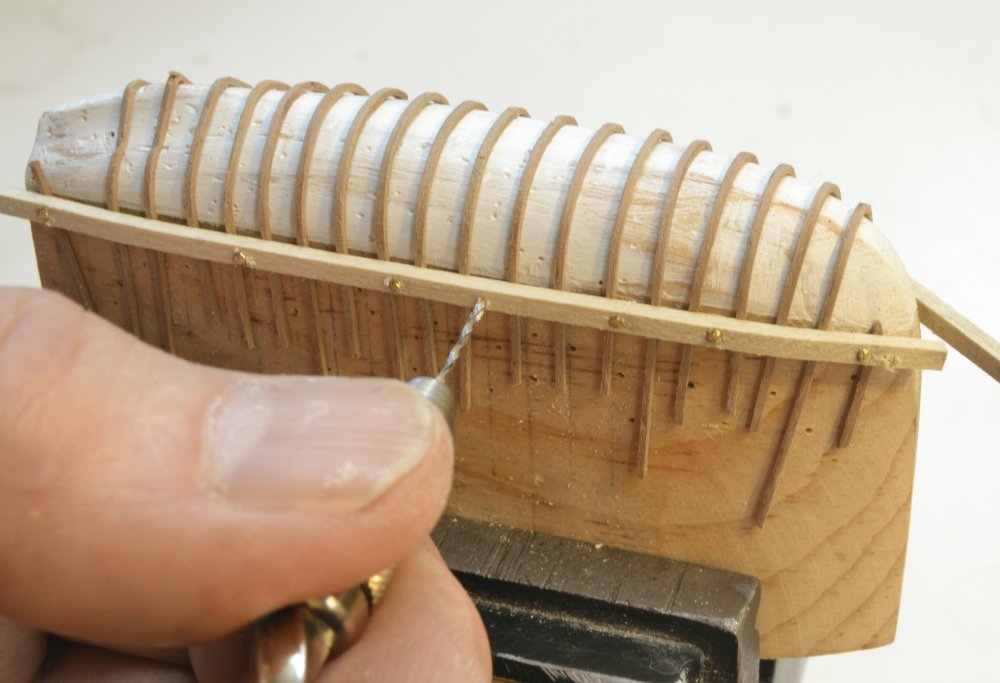
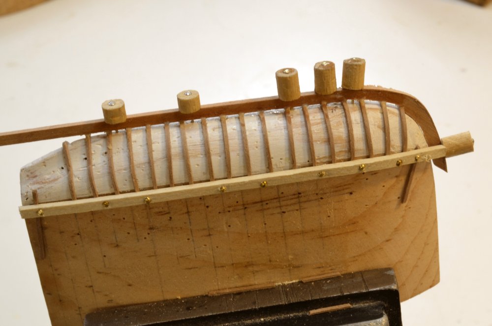
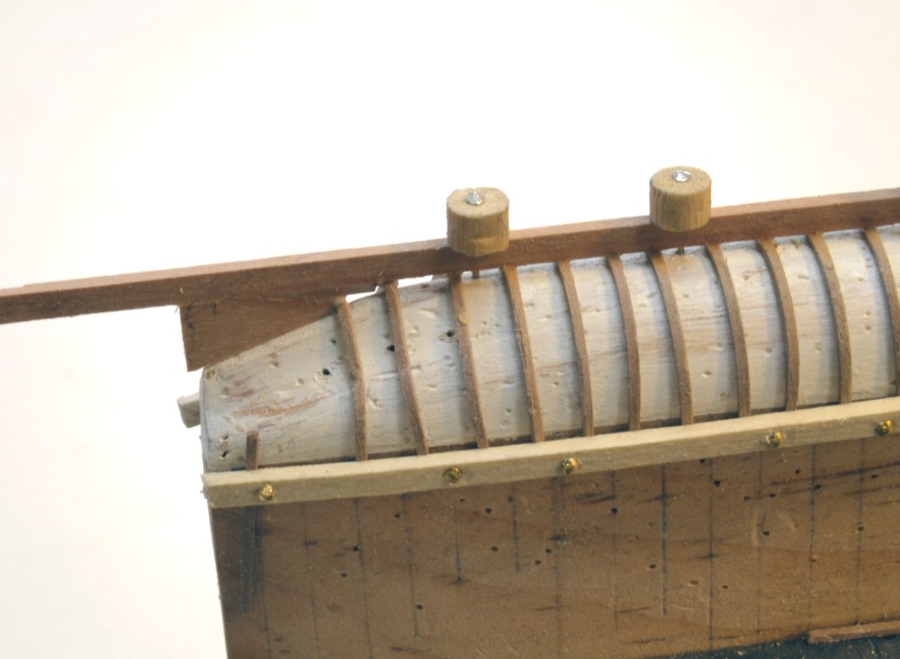
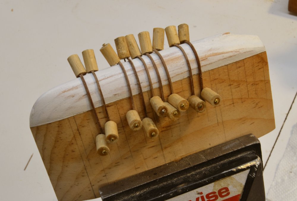
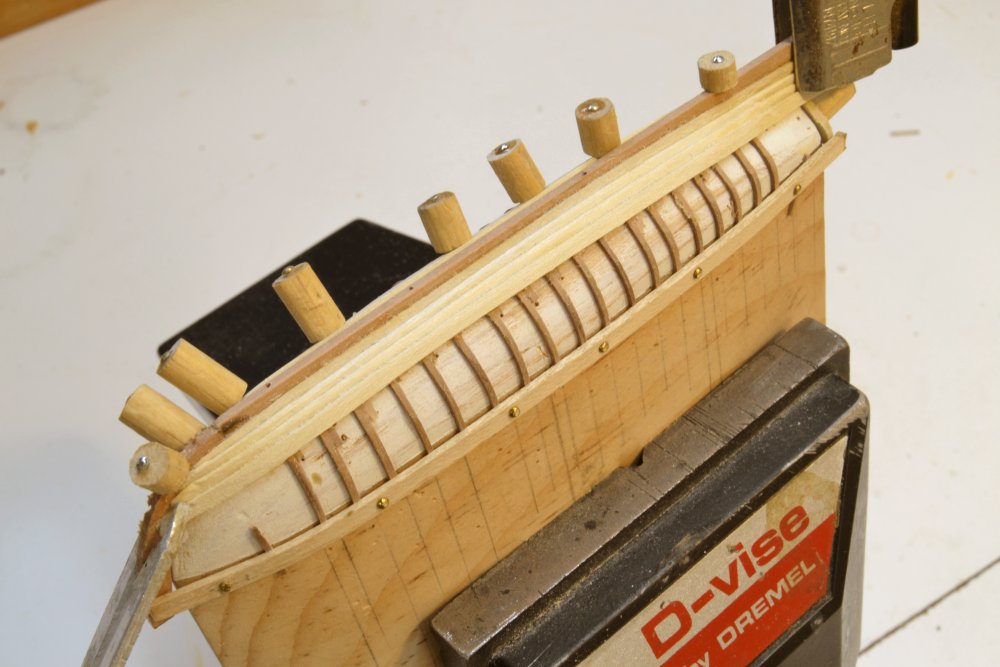
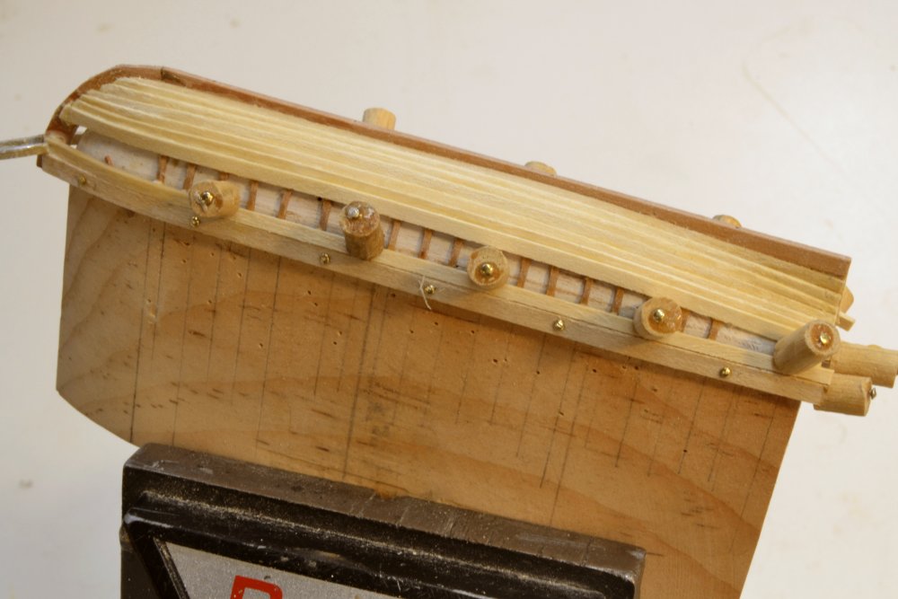
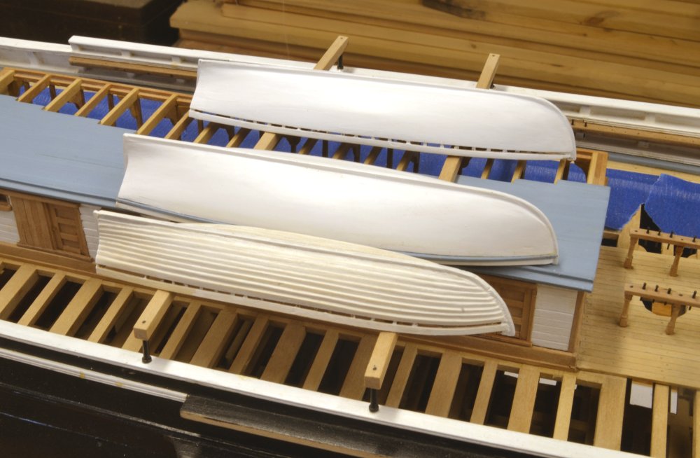
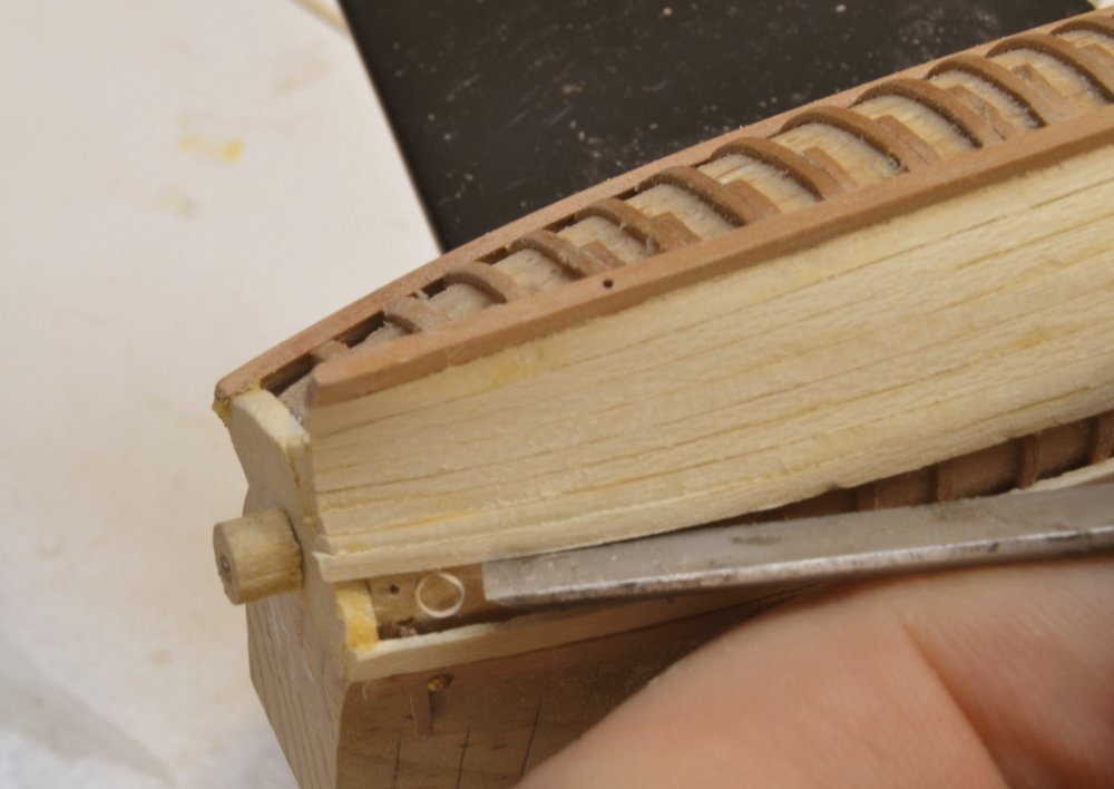
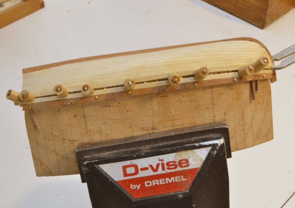
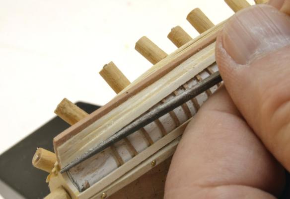
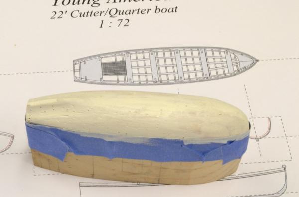
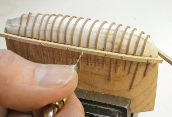
Young America - extreme clipper 1853 Part 151 – Ship’s Boats 7 Thank you for the comments and likes since the last post. I am looking forward to completing the work on these small (3 to 4”) long boats! After the last post I made some modifications to the 25’ clinker built cutter. I took some advice from my good friend Druxey that the lapstrake planking needed to converge to a carvel form as it approached the stem and stern rabbets. This is well illustrated in his posting on the Greenwich barge. I applied a cosmetic fix to the installed planking as shown in the first picture to remove the overlapping at the ends. The clinker style overlap at the rabbets would cause a complication in sealing and that is probably the reason for bringing the planks flush at those points. Anyway, because of this, I decided to lapstrake the 4th boat using the correct process. I had intended to make this carvel planked, but decided I needed to do one more clinker to fully understand the correct planking process. The next picture shows another view of the current state of the first three boats. You will notice that eyebolts have been installed in the skid beams and the boat sterns have been lettered. The next picture shows the plug for the 4th boat, a 22’ cutter that will be suspended from the starboard quarter davits. I reused the 25’ cutter plug as a starting point for this, hence the pinholes. The plug has been primed in the picture – not very photogenic I’m afraid. In the next picture the frames have been bent over the plug. They of course need to be aligned. The first step in securing them is shown in the next picture. A temporary guide and holding strip has been nailed to the plug over the frames at the boats topside height. A hole for an additional nail is being drilled in the picture. With the frames secured topside the stem piece is being fitted in the next picture. This piece was then pinned to the plug and glued to the first few frames. The keel was then fitted and glued to the frame floors as shown below. The last step before planking was to add the stern deadwood as shown below. This is glued to the keel. The connections are all pretty fragile at this point, but the addition of the garboard strakes will strengthen it significantly. Ed


- 3,618 replies
-
- 42
-
-
- young america
- clipper
- (and 1 more)
-
Yes, Bob, good assumption. Any drawings I use always go into the books. Ed
- 3,618 replies
-
- 4
-
-
- young america
- clipper
- (and 1 more)
-
Yes, that would do it, or even just a brass disk soldered below the pin head then pushed through the dowel - to provide a softer end and avoid denting the planking while still being large enough to push in - also, easier to drill just a disk. These are very useful, so it might be worth some work. Ed
- 3,618 replies
-
- 6
-
-
- young america
- clipper
- (and 1 more)
-
Thank you, steamschooner, Ian and Micheal and all those who clicked the like button. To answer your question Micheal, the "pin clamps" are either pushed in or tapped in with a small hammer. The pins are epoxied into the dowels but the grip is tenuous and some of them slip loose making insertion more exasperating. When the epoxy holds, they work very well - easy to push and tap in and easy to remove. An improvement might be to roughen the pins with sand paper before gluing, or maybe use longer pins and bend them somehow, but it is so easy to make more that I have not worked too hard on improving them. Ed
- 3,618 replies
-
- 8
-
-
- young america
- clipper
- (and 1 more)
-
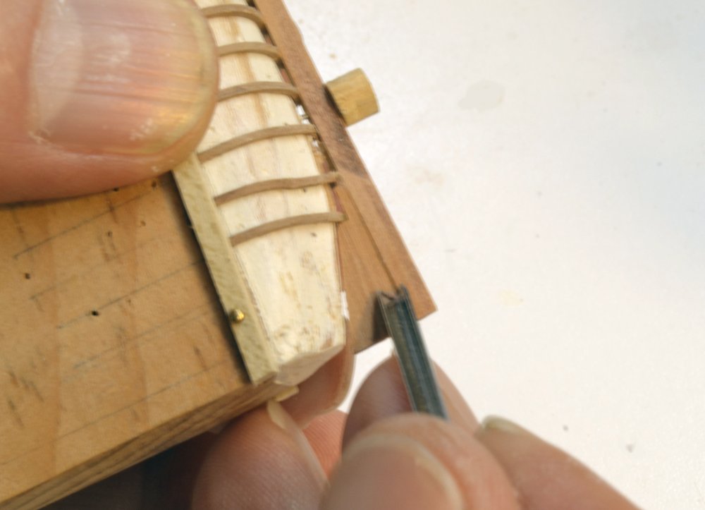
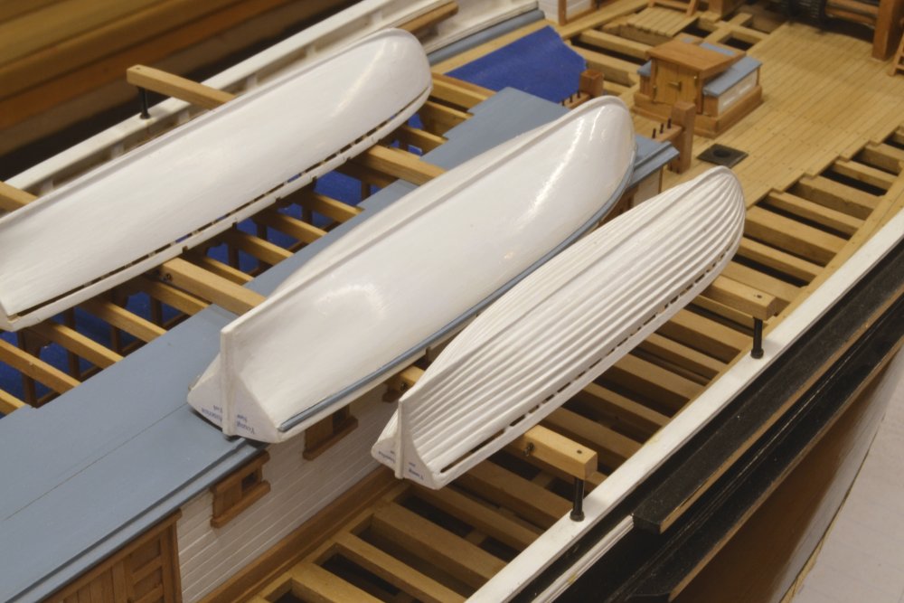
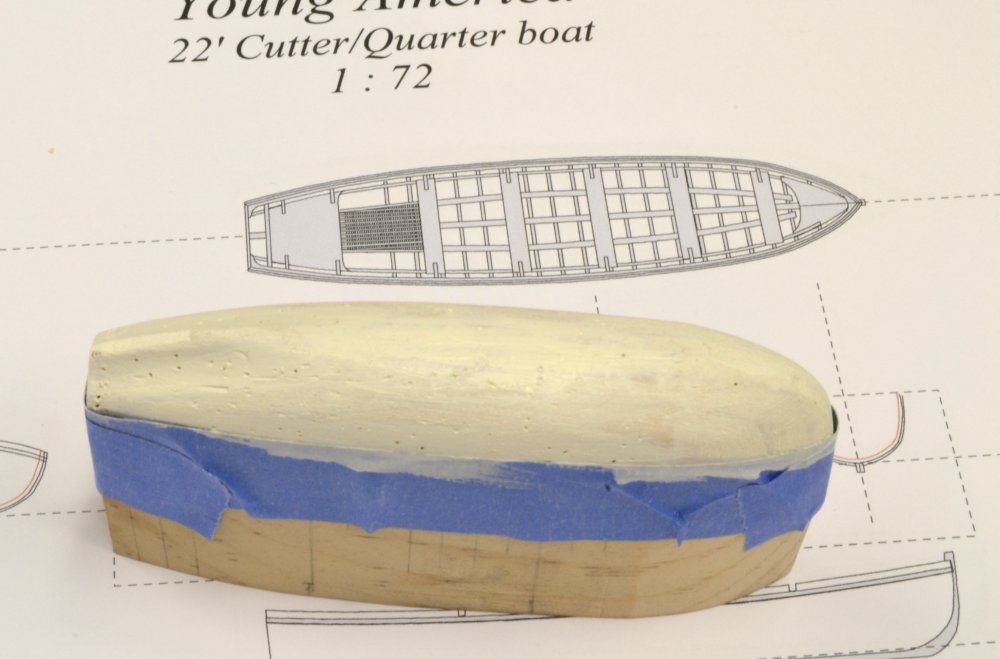
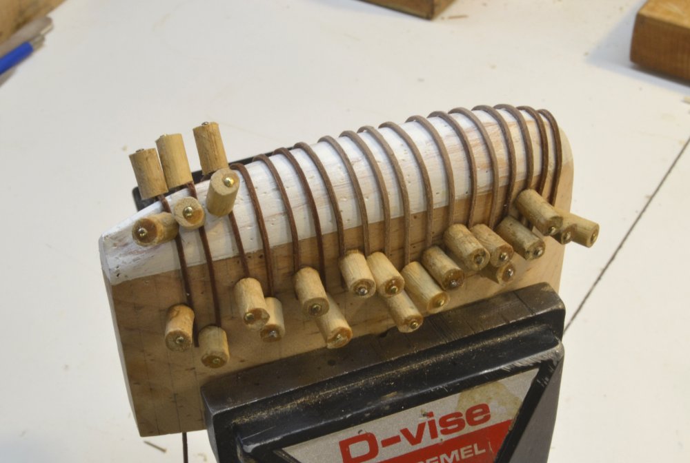
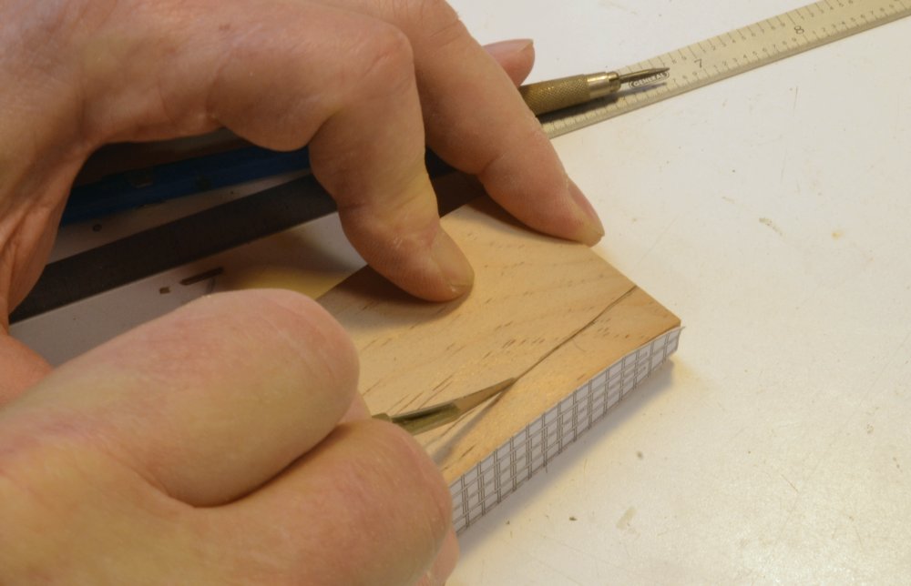
Young America - extreme clipper 1853 Part 150 – Ship’s Boats 6 In addition to the workhorse longboat(s), clippers carried smaller boats for convenience and for the safety of the crews. Government regulations had begun to exist to aid in crew and passenger safety. A variety of different types and sizes were used and it is most likely that boats on a given ship varied over time. With Young America’s long, 30 year career I am sure there were replacements. I am still pondering the fourth boat, but the third is to be a 25 foot clinker built cutter that will rest inverted on the skid beams outside the longboat on the starboard side. It is likely that the fourth boat – to be suspended from quarter davits - will be a somewhat smaller cutter. So, on to the first cutter. In the first picture, the sheer line at the top of the side is being scribed into the partially shaped pine plug. The boat pattern can be seen pasted to the block. This initial shape was formed using the disk sander. In the next picture the plug has been fully shaped and the area below the topside given a coat of white shellac, sanded and well waxed. The frames being formed in this picture are slightly smaller than the longboat frames. They too, are pear and were left in water overnight before being placed as shown above. They were about as flexible as string. The process being used is the same as for the longboats, but thanks to the learning curve, it is still evolving and becoming more efficient. In the next picture planking is well along. Planking began after both halves of all the frames shown were fitted over the plug, the keel assembly installed on them and the topside guide strip nailed over the frames as shown above. Frames at the ends were added later. The clinker planking requires more work and care than the carvel planking used on the longboats. First, because the planking lines will be very pronounced even after painting. Also, the upper edges of each plank need to be beveled to bed the next plank, working up from the bottom. The next picture shows the first step in that beveling using a paring chisel. On the carvel hulls the planks were tapered at the ends to provide fair lines and to conform to the contraction of the planked area at the ends. The same was done here before beveling the planks as shown above. After the paring step, a flat file was used to smooth out the bevels along the plank. The next planks were then overlapped and glued to both the plank above and the frames. The next picture shows the topside plank above the wale being installed against the guide strip. The next picture shows the planking nearing completion. In the next picture, the boat has been removed from the plug and some internal members have been added. As with the longboats, except for the unplanked boat, the internals are simplified on these upside-down boats. The last picture shows the cutter in its position on the skid beams. In this picture the boat has been given a first coat of white shellac primer, to be followed by the white acrylic. The wales on this boat – and the one at the top – will then be installed. The two longboats can then be secured, but this cutter will be left loose to provide access for rigging on the rail below, if needed. Ed


- 3,618 replies
-
- 48
-
-
- young america
- clipper
- (and 1 more)
-
Jerry, I spent some time this morning going through your build, including your first version. Sorry to be playing catch-up. There are so many fine builds going on MSW that it is very hard to keep up with them. First, let me thank you for purchasing the Naiad book and for the nice comments on it. Even better, I like the fact that you are adopting some of the ideas and tools. I think you are off to a great start on what I am sure will be a beautiful model. This is clear from the lovely joinery on the initial work. It looks great. By the way, the Naiad build log is still there on MSW. See the link below. I second Druxey's thoughts on wood selection, especially if your are able to purchase large stock and cut the model sizes yourself. Considering the overall effort on a model like this, to say nothing of the cost of tools and other necessities, wood cost is a small item, but one that has major impact on final model quality. Cherry is a lovely wood. I used a lot of it (along with European boxwood) on my first model, Victory. For subsequent work I switched to Swiss Pear and Castello. Cherry remains my favorite wood for other work like furniture, because of the beautiful grain as well as the color. Pear is similar in color to cherry, but the grain is generally much straighter, making it a superior model wood, but less beuatiful in grain for furniture, etc. However, I am sure you will be happy in your choice of cherry. I noticed that you have begun finishing frames with Tung oil. Keep in mind that once given an oil finish, glue will no longer adhere to it. My advice would be to hold off on finish until you are sure that gluing is no longer needed. Congratulations on your Unimat purchase. I bought mine - also used - in 1978 and have added many accessories since. Unfortunately many of these are now unavailable, though I do keep an eye on eBay - Toms Tool Store comes to mind as a source. The tool has been a reliable workhorse. I do have occasional problems with the original motor tripping my ground fault protection when it gets hot. So, I look forward to your continued progress on Poor Richard. Ed
-
Johann, these boats are simply beautiful and the internal detailing exquisite. Congratulations. Ed
-
Thank you everyone, and especially Micheal and Paul for their comments. I hope to have something posted on the clinker-built cutter soon. Ed
- 3,618 replies
-
- 4
-
-
- young america
- clipper
- (and 1 more)
-
Young America - extreme clipper 1853 Part 149 – Ship’s Boats 5 As longboat 1 was reaching completion, work progressed on #2. In the first picture the port side is being planked. The starboard side will be left unplanked, in frame. At this size I am not able to layout the planking strakes or even use a planking gauge as described in earlier posts and in the posts on the POB model. Instead, I install a full-width plank then trim its edges by eye so the planking lines will be fair and the last plank will just fit below the wale. The next picture shows the first step in that trimming of an installed plank. A paring chisel is being used to taper the plank. This is followed by final fairing of the plank with a barette file as shown in the next picture. Both these pictures show the half frames installed on the deadwood on the opposite side. All the frames on that side will be left exposed. The last picture shows the last plank below the wale being glued to the frames on the port side. The boat is now ready for removal from the plug for final internal work. In the next picture that has been done and the keelson is being glued to the frame floors. In the next picture one of the bilge ceiling members is being glued to the frames. The next picture shows the panel of grating below the stern seats and the supporting clamp for the seats on the near side. This will be the view of the framing and internals of this boat when it is mounted on the skid beams. The open pear framing has been given an initial cleanup but more work is needed to remove glue remnants and polish up the woodwork. Still to be added are seats and the mast step. At this stage the port side of the boat was ready for painting. The next picture shows both longboats positioned on the skid beams. Only some minor work remains to be done on these before they can be tied down. In the meantime work has been progressing on the first of the two cutters. Ed


- 3,618 replies
-
- 49
-
-
- young america
- clipper
- (and 1 more)