


Wintergreen
-
Posts
1,002 -
Joined
-
Last visited
Content Type
Profiles
Forums
Gallery
Events
Everything posted by Wintergreen
-
The planking in the last picture looks really good! Well done Jim!
-
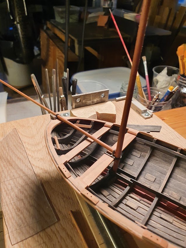
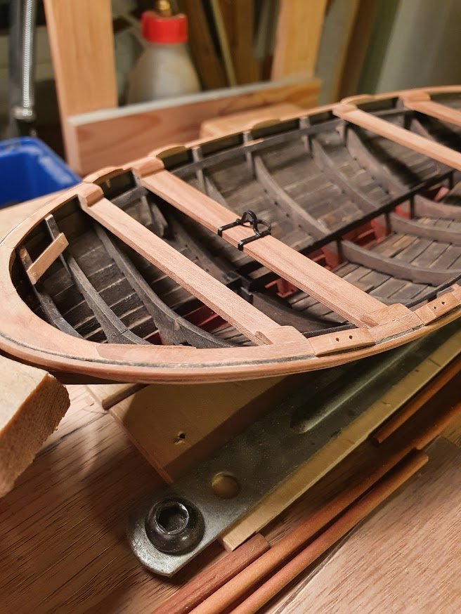
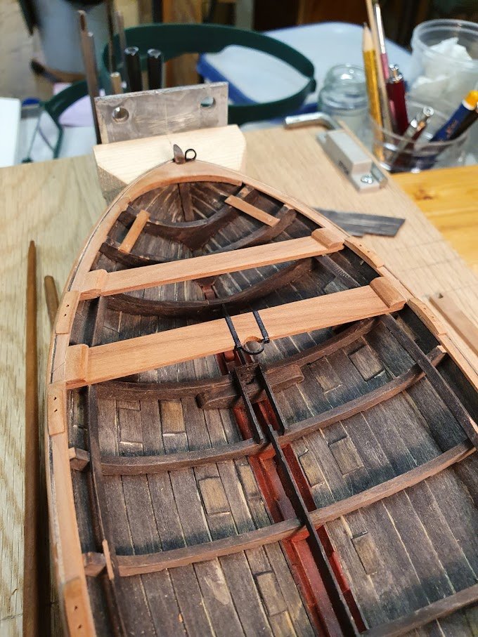
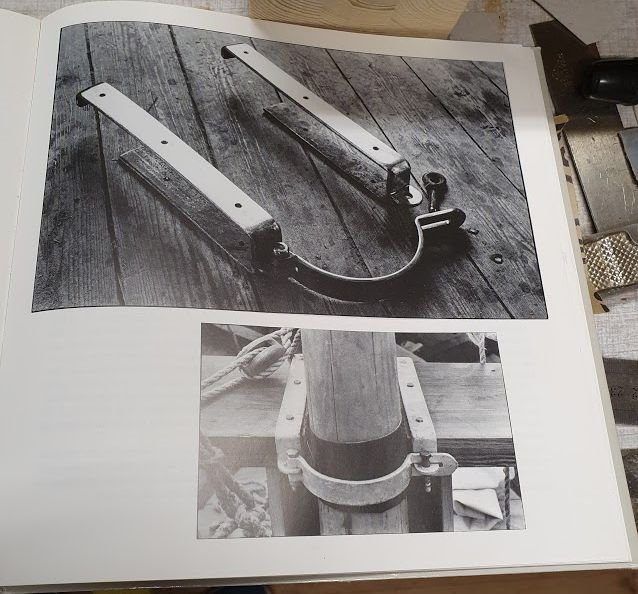
Alas! An update and how fitting, exactly one month since the last one...ehum. Age is just a number and slow is just a word. Well then, what has happened since last time. Oar locks or what they can be called. Four pairs. I also have been to the smithy for some metalwork. First the main mast partners and a ring for the job boom. Then some strap to retain the aft end of the jib boom. Looks like this with the spars in place. For reference, a picture from the book. It should of course be opening, but I took the broad road and CA:d the pieces in place. Since I like my new acrylic paints the brass is not blackened but painted (Paynes grey). Thanks for all likes and comments!
- 240 replies
-
- 10
-

-
Looks good! If you have a hole punch of some sort, you can always use painted paper. I saw someone making rescue rings that way.
-
Ain't that a remarkable little comment? There always seems to be something more to learn and master, even for a master. A soothing thought for us mere mortals at the beginning of the scale modeling path. Excellent build so far!
- 433 replies
-
- 6
-
-
- open boat
- small boat
- (and 1 more)
-
Great progress GL! Bumper edge, or rubbing strake I presume. This clipper will look splendid when it is planked and varnished. Ebony and mahogany - yummy to the eye 😉 Obviously there was no risk with the hull being deformed while gluing only one wale at a time since it is so well fastened to the building board. Keep it up!
- 153 replies
-
- 1
-
-
- Ancre
- Bruno Orsel
- (and 2 more)
-
While it is a replica it sure looks straight out of the dark ages! Lovely 🙂
- 179 replies
-
- 2
-
-
- longship
- Helga Holm
- (and 1 more)
-
Splendid job Vaddoc! Can't wait to see the screws gone 😉 The stem came out really, really nice. Excellent shape. Keep it up!
-
If it works for you, it definitely works for us as bystanders 🙂 Fiddly work nevertheless. Keep it up!
-
Nice work! It resembles these big canoes you sometimes see, with like 16 native people in them. Interesting. Keep it up!
- 179 replies
-
- 1
-
-
- longship
- Helga Holm
- (and 1 more)
-
Amazing detailing!
-
That chair looks in dire need of some oil here and there, and a good polish 😄 Just splendid! Of course it should look like that. Keep it up!
-
Looks like a very acceptable hull now! Never heard of a product like that, but it seemed to do the trick well for you.
-
One does not fully appreciate the size of this model until you let it linger beside an enormous iron or, like on the previous page chuck in a ruler. One nothing else is present in the pictures it is easy to forget that it's only like 6.5" or some 135mm long. I have but one word - Amazing skill (oh, that was actually two words, well well)
- 433 replies
-
- 10
-
-
- open boat
- small boat
- (and 1 more)
-
It starts to look busy now, Bolin. Quite some skeleton. Looking good. Keep it up!
- 179 replies
-
- 2
-
-
- longship
- Helga Holm
- (and 1 more)
-
Bowsprits can have they're back end fastened between to sturdy vertical bits. But design varies of course. As for filler, I would use fine filler from the hardware store. The one you use for covering up nails in trimmings and such. Usually sold in plastic tubes.
-
I think it's twofold if you should leave the planking or rip it off. Leaving it on pays credit to your sons work and it doesn't look that bad from what I can see in the pictures. Putty, sanding and paint and will all look splendid. If you rip it off, where to end the "rebuild"? 😉 As for planking stock I have no real input. My next ship will be planked with birch but it all depends on what is available and cost.
-
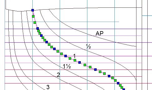
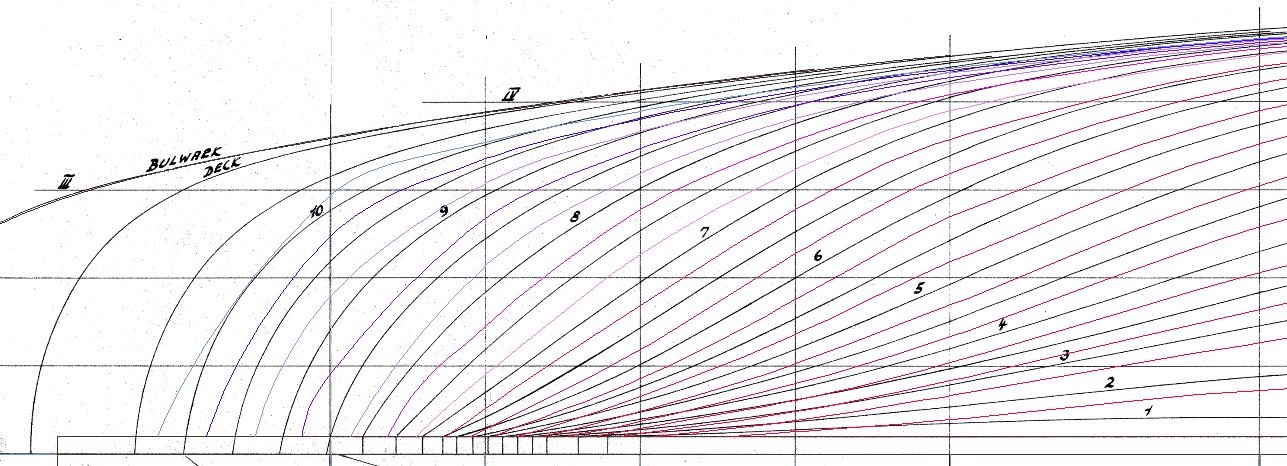
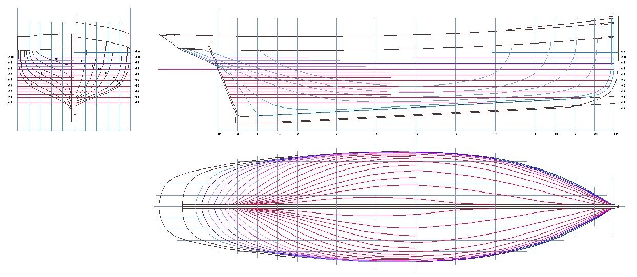
1.1. Preparing for lofting frames To address the issue of “Lines to outside of planking” work started over. The body plan was traced yet again, this time with correct width or breadth. To move all station lines to inside of planking the offset function was used. It creates a line offset by the distance you type in, taking into account curves and all. There is however one disadvantage with the offset, or any of the other “line copy” functions. It creates a line with a myriad of nodes, or control point. Se picture below with the traced line and then the line created with the offset function. The effect of this is that nothing can be done with this line. It is not feasible trying to adjust it or so but the solution is quite simple, just trace a new line on top of the offset line and remove the offset created line. Now we have a line that can be tampered with without too much headache. Rinse and repeat and all station lines have been moved 65 mm inwards in a nick of time. Next step will be a new half breadth plan where water lines start from the inner rabbet line and follow the inside of planking. It is straight forward. Remember to hit CTRL+S to save your work every now and then. TurboCad dies on me once in a while and recently I lost last some half hours’ worth of work. Be sure to use the curve tool that goes through its control points, not the other one. That will leave you with a host of problems later. Once the new half breadth plan is done, fairing comes next. Even though the Bezier tool creates nice curvy lines it can’t for example foresee the shape of a counter stern on a boat. Next picture highlights some areas that needs direct attention. On top of the plan is the created water lines. Close to the centerline it is obvious that water lines 7½ and up needs addressing. But look further up also, especially 6½ and 8 have unsightly bumps and dents. If left there is always the possibility to fair the wood frames once installed. But that will create an erroneous shape on the transom in that it will be pointy. Around the centerline the transom should be smooth and round, not sharp with an edge. After some fairing and adjusting the lines plan is finished. Next up will be lofting all frames. A quite repetitive task but better get used to it since there will be more of that down the line. As I've mentioned before, anyone interested in a more detailed instruction regarding lofting in CAD should read the work of @wrkempson found here: https://thenrg.org/resources/Documents/articles/DraftingShipPlansInCAD.pdf It is really good and instructive. Thanks for your interest in this and please keep on asking and discussing. Much appreciated!

-
Honestly John, I have no idea. Busy doing chores probably? So what do I need to do, call you 😉 Jokes aside, thank's for popping by. Much appreciated. note2self - check up that ant's pyjamas 😏
-
That was quick going! Did you build it in just about 4 weeks? Incredible. And a interesting alteration with guns and Jolly Roger 🙂 Well done!
-
No fool like an old left handed fool
Wintergreen replied to Don Case's topic in Modeling tools and Workshop Equipment
Not to speak about a regular carpenters workbench... designed for right-handed people. You could of course build your own like Mark (Sjsoane), but that is taking it to another level. I've trained my right side so I practically can do almost everything that way. It does not feel that comfortable though. Apart from brushing ones teeth hadn planing is the hardest. Especially edges and bevels. -
Well you know the saying @druxey, that prominent people arrive late 😉 You're most welcome. There are refreshments in the kitchen and enjoy your stay 😁
-
Just stumbled upon your thread here. That planking is seriously good! Well done, mate! As for the order of building, like you did with full width deck beams for rigidity is just the way. Frames and hulls can be delicate business and anything that makes them more rigid during building is a welcome addition. Also the framing of the cockpit looks spot on. Keep it up!
-
A 28 ft cutter at 1:48 - that will be kind of tiny. But then again, what else to except from an expert 😉 I will follow with interest. The hull looks promising judging from the drawing. Also, from what I can see I guess it will be carvel planked?
- 433 replies
-
- 4
-
-
- open boat
- small boat
- (and 1 more)
