
HOLIDAY DONATION DRIVE - SUPPORT MSW - DO YOUR PART TO KEEP THIS GREAT FORUM GOING! (Only 20 donations so far - C'mon guys!)
×


popeye the sailor
-
Posts
16,007 -
Joined
-
Last visited
Content Type
Profiles
Forums
Gallery
Events
Everything posted by popeye the sailor
-
 basically, all you need is the emulator to play old games. I go to DopeROMs for NES, super NES, and other early platform games. for other games, one can go here: Download Games | PC Games and Mac Game Downloads at Direct2Drive in my early days of computer play, I dealt a lot with DOS. I have some games I'd love to play, but they need to be formatted to the newer platforms. I recently got Diablo 1 to play on windows 8.1 I did happen on a site that deals with DOS games......haven't looked into it yet though DOSBox, an x86 emulator with DOS I also have a program that keeps windows 10 from barging into my computer...at one time, they geared it to self install when windows XP {my favorite} got old and windows 7 took over...somewhere around that time frame. a couple of Christmas's ago, the admiral got me another platform that will allow me to watch movies, and play the older games on newer televisions....it's the absolute rage! I can watch movies that haven't even gotten to DVD yet.....hot off the press I'm not a fan of steam.......too much can be found for free. that's like Warcraft........why but the game, and then have to pay for the platform to run it......silly if you ask me. I'm not a fan of sims either......mostly hack 'n slash and first person shooters. I love a game that has a lot of puzzles. I'll be back.............
 -
thank you good sir have a merry Christmas!
-
Magnum P.I. Ferrari.......I've seen that kit around......
-
it was a model Kurt........the admiral would kill me if I drove something like that to the house! although a friend of mine would likely take it off my hands......he collects the full size trucks {he already has a pumper}. trivia....to drive a vehicle such as that on city streets, you would have to remove all the markings and likely the color too, so not to confuse it as an emergency vehicle. to keep it as it is, it could only be used in parades and fairs. my son bought a short based school bus for his business and he had to repaint it {the markings had already been removed}. he has five kids.......I told him to hand them a paint brush and go to town!
-
and a very merry Christmas to you and your as well! 🎅
-
there might be another learning curve, bringing over to wooden ships, since the paint does tend to sink into the wood. you may find the need to seal the wood before paint. might be fun to try though
-
that would be more noticeable with the insignia I saw that later after I had put them on. one had already split on me {the flame area}, so I decided to leave them as they were. thanks for the very kind word.....this one was the easiest one I've done......the black put everything in my favor. not only that, but even though they were one scale size short, the decals worked well on the model. the decal sheet supplied in the kit were wrong for the model subject.......if I can get another Dr 1, I will make sure that it IS an F 1, so I can use the sheet......perhaps I can do Foss's plane. I have the face for the cowl. I did see a kit that was missing the decals, but I didn't want to shake the Santa tree too severely........didn't want him to get mad at me I do have a pair on my list though.......Dr 1's and D VII's are my favorite planes, and I had these two on the list before I saw it. another problem I'm having, is that someone has been taking inventory of my stash {and current projects}, and may make future purchases harder to get approval for. now I'm sure that I have some in the stash that will prove to be interesting, but seeing others that might be even more interesting, may get passed over. I doubt that this scenario would come to pass, but it means that I need to pick and choose what subjects deserve merit I'll keep you posted
-
the plane is looking very good.......the camo looks sweet! very nice
-
I almost bought a ladder truck........now your gonna make me regret it super start on 'er...looks great!
-
bad break on the light issues......looks to me like you were on a roll! that is the type of light that I have on my main table.....I don't like it. I want to set up a crane light {or even two} because it's easier to replace a bulb, than a florescent tube. sorry to hear of your issues Ken......hope a remedy is in the works for you
-
good to develop a direction in which to build........the fuselage is look'in really good I also share the thought of a wrap around instrument panel....are you working from images of the plane?
-
coming together very nice!
-
look'in very good Kevin .....the redo is much better!
-
might be good to adopt a rivet pattern for the fish plates...images should give you ideas pretty neat project!
-
I have been fortunate to have followed you from the beginning.......watching you evolve, and the village thrive. I am so impressed with your workmanship, balancing the use of wood and mortar...your vision is quite strong you latest creations are absolutely incredible. what looks like the edges of the parameters are met......you see the vision that there are no barriers and your world is infinite. that is the earmarks of the perfect model....no matter how much you add, it does not create overkill and doesn't upset the applecart! {I'll bet there's even an applecart in there somewhere } where do you plans on showcasing this masterpiece......don't you think it ought to be put there, before you reach the vale?
-
yea......I'll do what I can concerning the gear situation.........glue them open I suppose. I will try to modify the other parts and add them.....pictures coming. I did get a good idea of that is between the white stripes.......nothing.......just a normal separation. I did paint white in the gaps and will do the same for the other stripes. there are no pictures yet......ben busy with Christmas stuff. as for the tail heaviness.......as mentioned, I just make and paint a base for it and glue it down. I can agree with that Egilman........where I have the props in the up position, it likely upset the balance. even with them on the model, it doesn't change things. it does look cool though......it's a very nice kit so close to the big day..........I hope I can do something on it
-
looks great!
-
to add to it............I've never seen it done this way either. I've not seen it done in the opposite......no matter how it's done, getting away from gaps is futile, due to the fact that they are separate parts. as most have done, a good filler is used. now if your a steady hand, you could carefully squirt a small amount of liquid CA into the gap and let it run down the seam. don't touch it!....let it dry. I don't use fillers too much.......reason being is the sanding that has to be done after. you could lose some detail and rivet lines. a fine needle point will deliver the Ca without getting any on the outer surface.
-
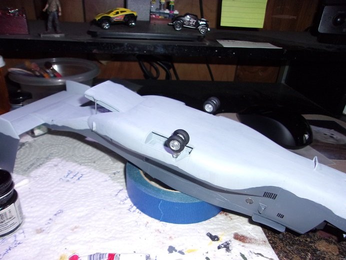
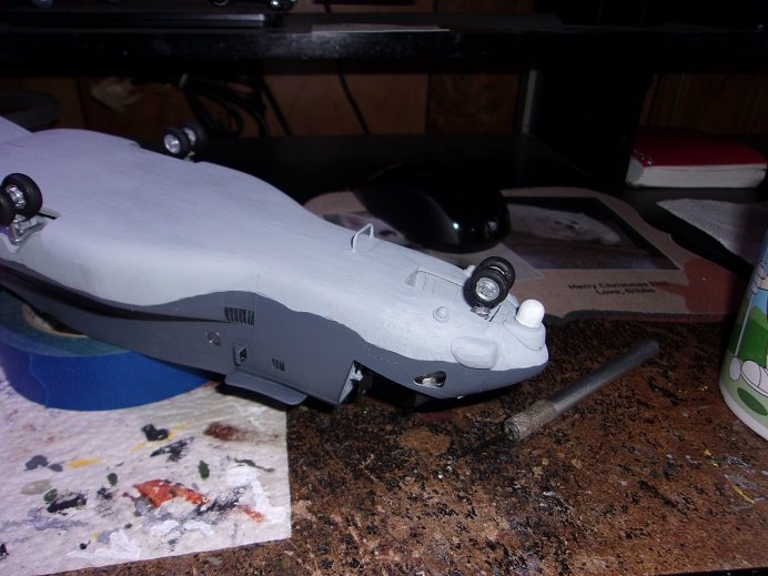
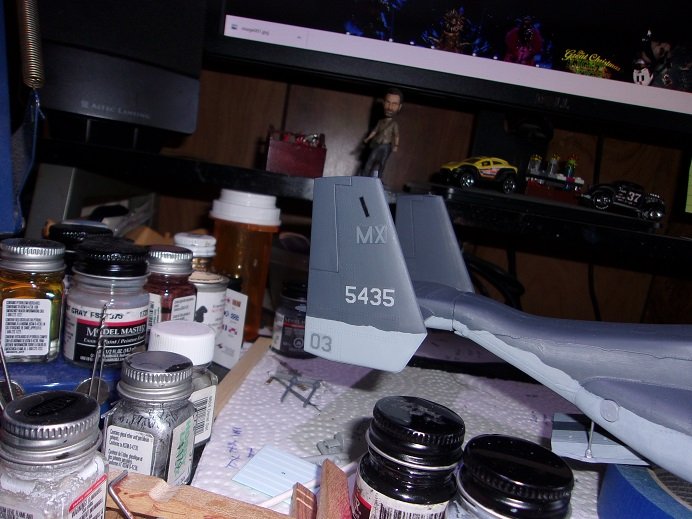
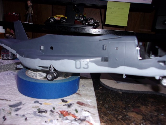
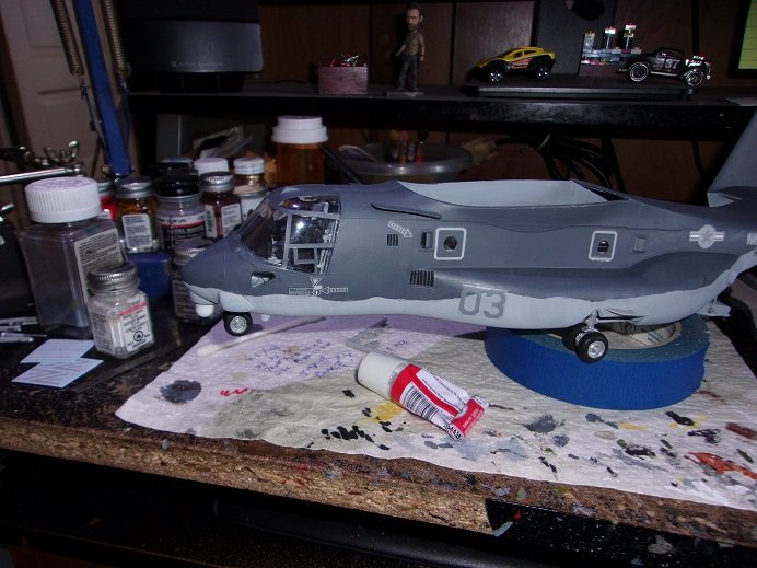
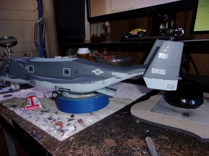
OK.........that was a long wait...huh? so..........Murphy must have visited me at one point........never even saw it coming I had painted the tires and assembled the gears...later gluing them onto the model. what I didn't see was that I had cemented the rear gear buckets on the wrong side. I painted the parts involved, saw the holes where they located...but somehow got them mixed up! the forward gear door was to be closed.......I can't do that now. nor can I add the parts for the gears. the nose gear is fine.......I couldn't screw that up.......so this problem mainly pertains to the rear gears. I also see that the weight is needed......this is a tail heavy model. there is a fix though.......I will make a base for it, and cement it down like I did for my F 15 Eagle {not a big deal}. this puts the gears too far forward........gonna be some surgery, I can see that! looks like it's up to you Lou........your going to have to be the one who comes out with the perfect model. Italeri makes a very good kit. for anyone who wants to add an Osprey to their collection, this would be the kit to get. as mentioned, the nose gear is not affected. I still need to paint the other two cameras {the smaller nodes}. a lot of yesterday's work { and today} has been geared toward decaling the model. the outline around the door on the starboard side has been hard to set......I had to apply it with decal set....the insignia has been a problem as well....I think it's the Ghost Gray, that is behind it, since it looks flatter than the Gunship Gray. I added a few parts as well.........the canopy glass.......the fins near the rear landing gear.......the dorsal fin and radar, along with a few more decals. so now I've set it aside to dry......
- 96 replies
-
- 10
-

-
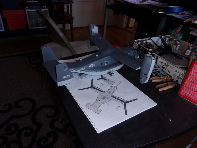
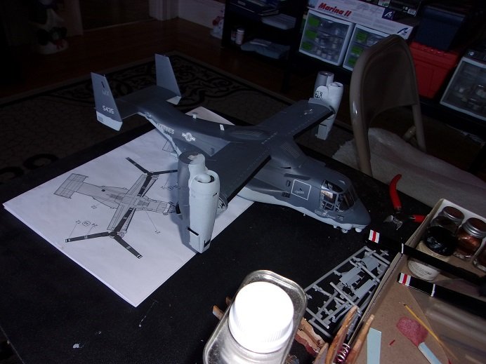
to think that's where we're heading........we have unmanned drones already! I made progress towards the finish of this model. I had to toss a couple pictures though because of blurriness, but I made more progress today, and I will have that up as soon as I can get them out of the camera. the hydraulic arms were cemented in place, connecting the lower part of the door to the body. the upper part stays where it is.......no cement needed.
- 96 replies
-
- 11
-
-
from out of the clear blue.......you have a piece of the ocean neat way to do it! love the color tints....
-
Billing Boats sell what they call 'pick 'n place tools........same thing what you have there......a poke stick with a sticky thing on the end. all mine, the sticky thing came off, so now I use them to position decals. not recommended around sawdust
-
I think that's larger than 33 mm........the one in the hardware kit is 1 1/8 {28-30 mm}. it gives me something to work with thanks!
-
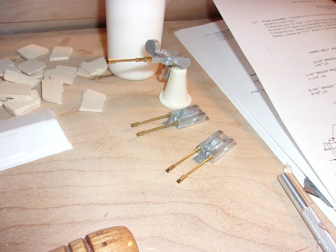
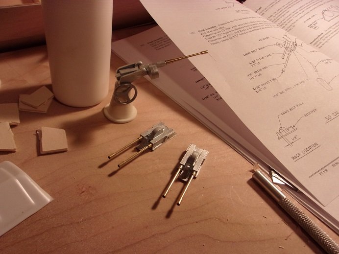
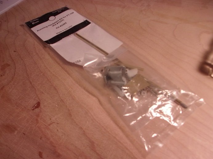
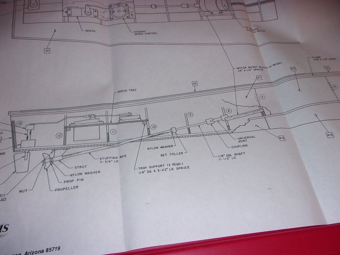
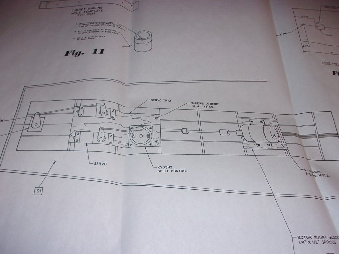
there is the engine room 'roof' still to make {it's a raised hold on the deck}. we finally arrive to where I'm at with the project. it's the reason why I started the log......Mike {Mog} is assembling the guns........and they look very different than mine. mostly made of metal, they seem a bit crude and lack finer detail. if I were to make this an R/C boat, I'd probably be good with it, but where I'm planning to do a static model, I'm tempted to go an extra mile or two. Mog's doing a fine job with his......he even has the turrets caged up. I'm not there yet. here is where I am on the 20 mm gun and the 50 cal machine guns. do not try to solder this metal......it doesn't end well.......'least not for me anyway. I ended up using CA. I've add a bit more to the machine guns......gotta make the shoulder rests for them. I broke a few bit drilling the holes. I'm going to look them up to see what they really look like, and perhaps I'll try to scratch build them { the machine guns anyway}. the other thing is the running hardware......I just took these pictures, so they're hot off the press the running hardware is just that.......the hardware. you get one rudder and one prop assembly. if I planned to run her, I'd need to get the motor{s}, rudder servo, and speed servo {I say motors because I'd want two props}. if Santa smiles on me for Christmas, I might find a kit, complete with all the hardware, to build an R/C vessel, under the tree here are the diagrams that Dumas supplies. I went out a short time ago and cleaned the driveway due to the wind........the storm is over..... depending where you were in the state, you could have seen as much as 3 feet! it hasn't snowed that much in quite a few years. when I was a young lad, living in Weare N.H.......a stone's throw from Goffstown, New Boston {nowhere NEAR Mass.}, and Concord, two feet was a normal storm for us. but I'm happy.......we will have a white Christmas.
-
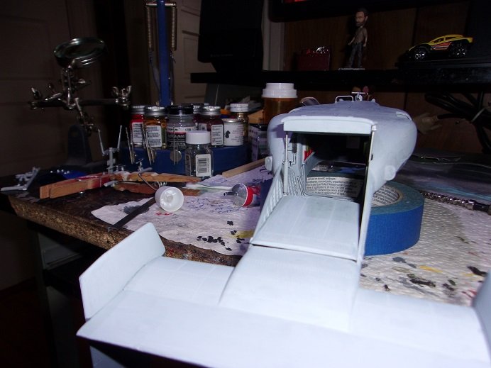
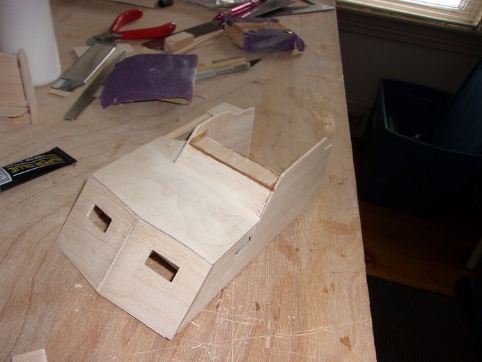
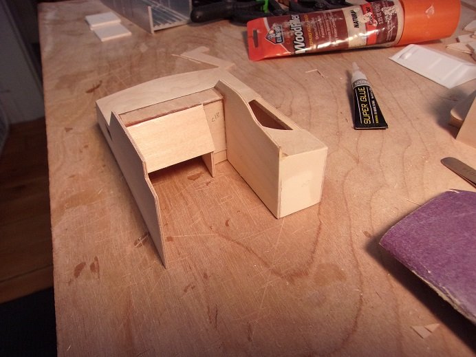
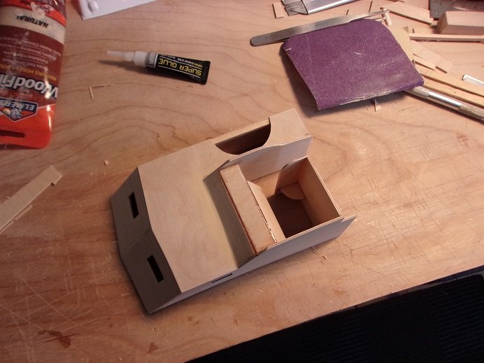
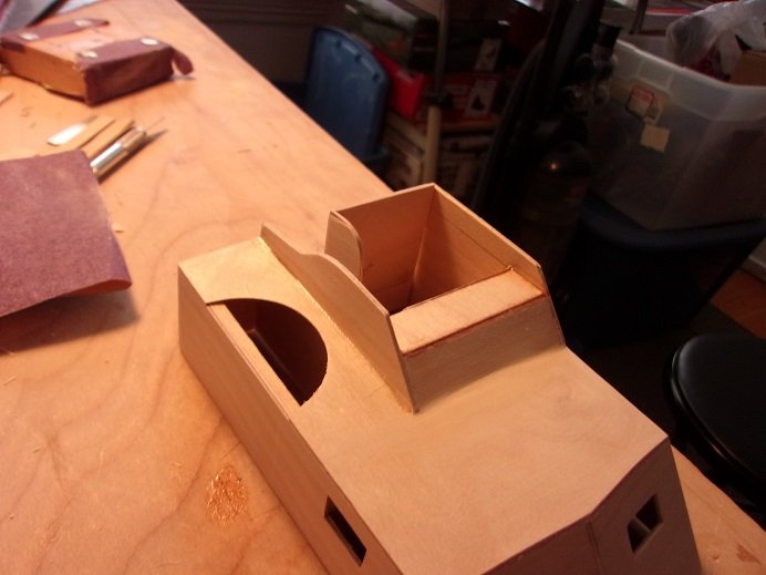
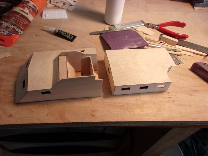
more on the interior of the helm......... then the instrument panel face....... the companionway door is on the right of the instrument panel .....all under there was closed off. with the port divider wall dry fitted in place, there is enough room. this is the way the layout looks like on deck. there is still more to add........I'll get to that a bit later.....I now want to see what the armament looks like.
- 221 replies
-
- 10
-
