Supplies of the Ship Modeler's Handbook are running out. Get your copy NOW before they are gone! Click on photo to order.
×


DelF
-
Posts
1,409 -
Joined
-
Last visited
Content Type
Profiles
Forums
Gallery
Events
Everything posted by DelF
-
 Well done Glenn. I always feel better if I put a mistake right rather than bodge it. Btw, I now know why there's a world shortage of clamps - you've cornered the market!
- 476 replies
-
- 4
-

-

-
- sphinx
- vanguard models
- (and 1 more)
-
Good question. However I'm only using it on the lightest pieces of PE on flat surfaces so hopefully they won't need to stand up to any wear and tear. As for longevity, I've not found any references to it degrading quickly so I'm keeping my fingers crossed that it'll last me out. With heavier PE and pieces that have to fit on curved surfaces I'm using CA.
- 345 replies
-
- 1
-
-
- Duchess Of Kingston
- Vanguard Models
- (and 1 more)
-
Hi David You've made a fine job of that stern - I think it was well worth the effort to fill in that gap and create a smooth cap rail. Your planking also looks particularly beautiful as it runs up into the stern. Before you get on to the bow area you might want to check this potential problem I've described in my log. I can't claim to have spotted it personally - I read about it in Glenn and Rusty's logs - but I thought I'd pass it on in case you hadn't picked it up. Derek
-
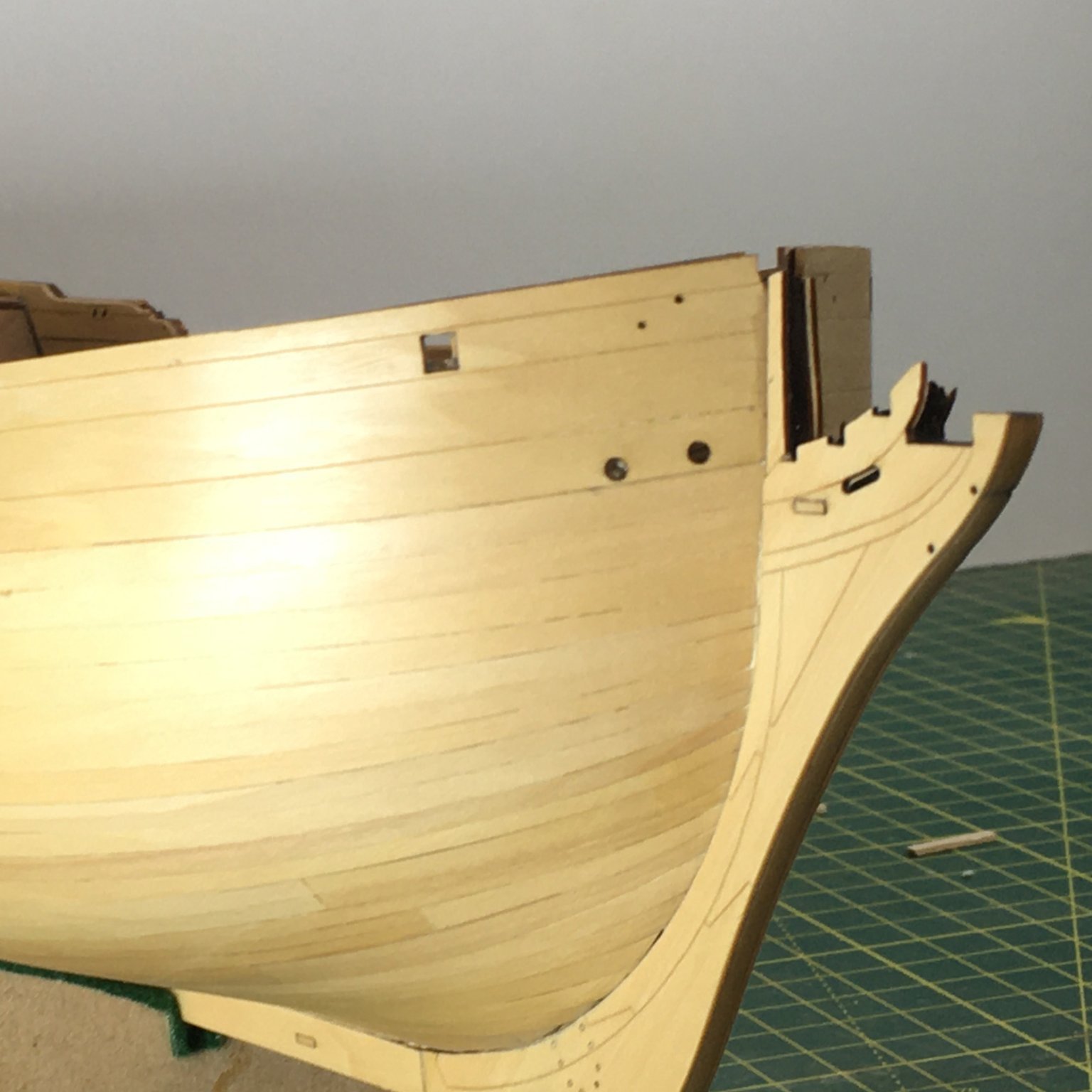
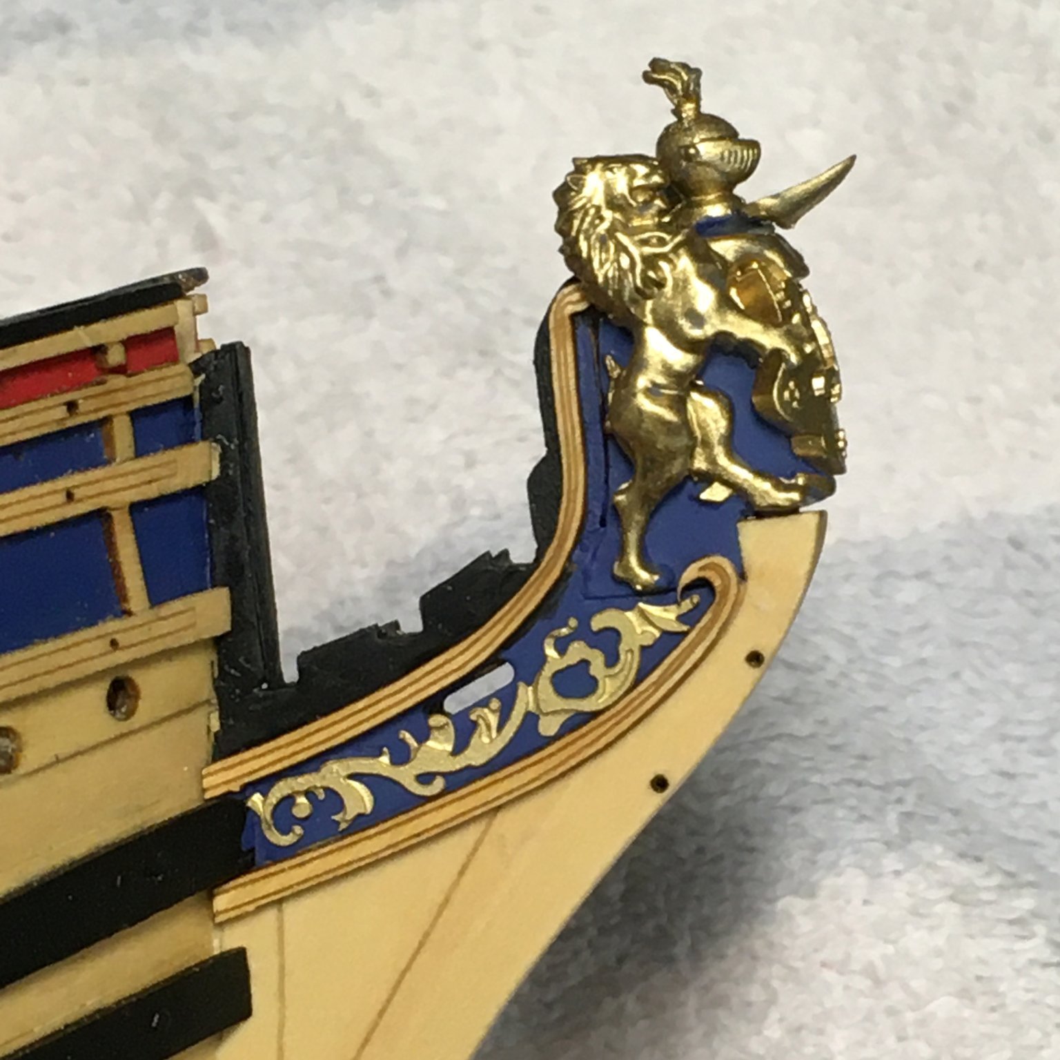
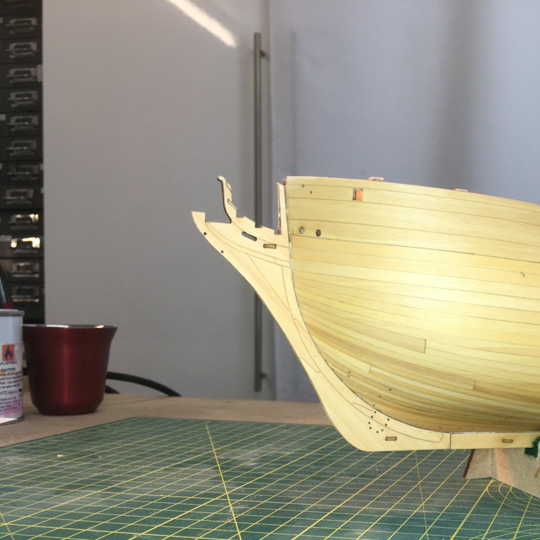
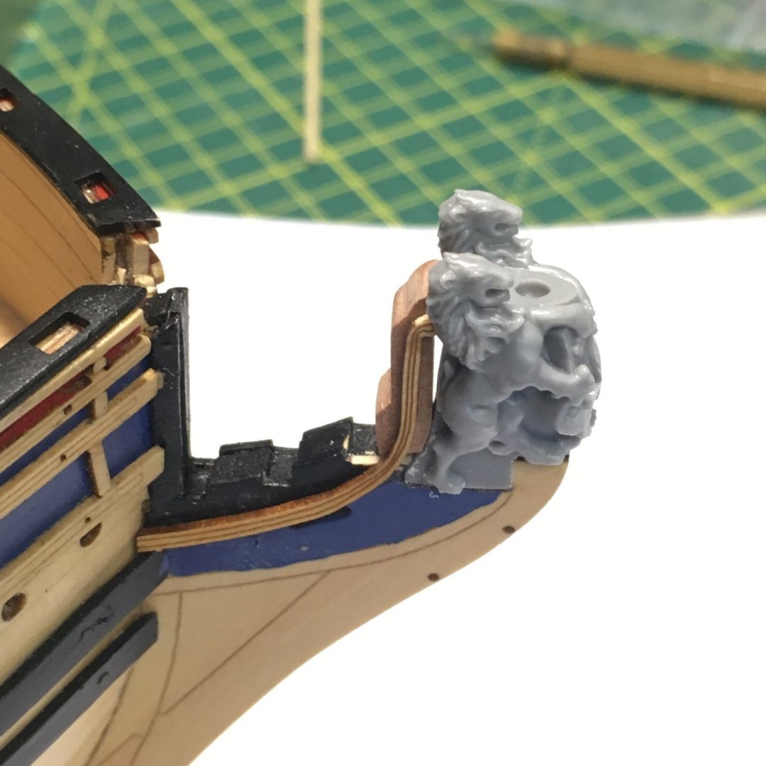
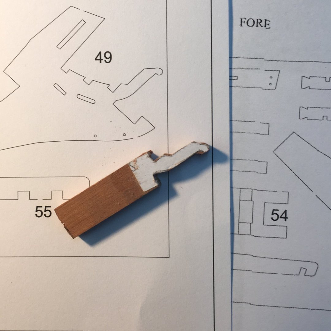
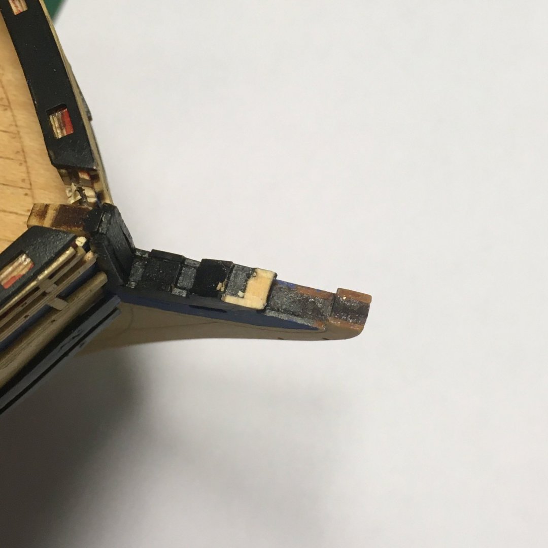
Fixing problems in the prow Whilst work was progressing steadily at the stern, things haven't been going quite as smoothly at the sharp end. Sometime between these two photos I managed to snap off - and more importantly lose - the fragile curly bit: I gave up trying to find the errant piece in the black hole that is my workshop and decided to make a replacement from a piece of scrap pear. This is where Chris's scale plans showing every component are particularly handy, as I was able to photocopy the part and stick it to the wood for shaping. Here it is approaching the final shape: I departed slightly from the original model which consists of three layers - a 3mm wood core sandwiched between 1mm veneers. The latter are a slightly different shape to the core, creating small cut-outs in the final shape (these are visible in the first photo above). I decided I would use a single 5mm thick piece based on the shape of the 3mm core, and wing it if and when I needed the cutouts. After trimming the broken section to provide a firm base I dry fitted the new piece along with the figurehead and upper cheek rails. More work needed! Important note for future builders It was at this point I remembered a warning I read in @glennard2523 and @Rustyj's logs. The manual tells you to fit the cheek rails first, then the figurehead. Unfortunately the figurehead has a dovetail-type base which means it can only slide in to the prow from the side, which will be obstructed by the lower cheek rail. In fact the rail in the manual has been broken to fit the figurehead. Chris got the order right in the plans (Sheet 5) which describe and illustrate a very clear set of steps for constructing the bow area (@chris watton for info). Anyway, to cut to the chase, here's the current state of play, with the repair in place along with the figurehead and cheek rails: Now I'm looking forward to fitting more of this lovely photoetch decoration. Derek


- 345 replies
-
- 18
-
-
- Duchess Of Kingston
- Vanguard Models
- (and 1 more)
-
That looks great!
-
Working out the correct height of the masts from the Deck
DelF replied to DaveBaxt's topic in Masting, rigging and sails
I agree he could have been more explicit. However in the first page of text he describes the taper of the fore and main masts from the heel to the head, so it's clear to me he's referring to the whole mast from then on. His work is based in large part on the instructions given to dockyards on the construction of masts and other spars, so when a mast length is given (and parts of the mast such as the head are specified in proportion to that length) that dimension must surely refer to the overall length. -
Working out the correct height of the masts from the Deck
DelF replied to DaveBaxt's topic in Masting, rigging and sails
Hi Dave See my previous post. I definitely think you must be (understandably!) confusing the overall length of the main mast with the length of the first and largest component, also called the main mast. Also, the formula in use in Endeavour's day did not include the length - that was only used before 1719 and after 1793. The formula for the main mast (assuming Endeavour was refitted per RN standards) would have been beam X 2.28; main topmast = main mast X 0.6; main topgallant = main mast X 0.49. -
Working out the correct height of the masts from the Deck
DelF replied to DaveBaxt's topic in Masting, rigging and sails
Sorry Dave, I don't know how I let my eyes deceive me on that one. It's strange, because it makes the mizzen look very short especially compared to other models of the period (such as plate 61 of the Victory of 1737) where the mizzen cap looks almost on a level with the main top - which is what you'd expect from the proportion calculations I mentioned earlier. I think this is a separate issue. 293mm must be the overall length of the mast from the heel of the main mast to the truck of the main topgallant. When I cited the length of the main mast I was referring to the first of the three components of the mast, ie the main mast, main topmast and main topgallant. The main mast length is proportionate to the beam, the other two to the main mast. The overall height of the mast is these three added together minus the two overlaps. Just seen your latest post - I'll stop this now for a quick response. -
Working out the correct height of the masts from the Deck
DelF replied to DaveBaxt's topic in Masting, rigging and sails
Hi Dave I don't believe Lees only covers rated ships. As a fully ship-rigged vessel refitted in a naval yard I'm reasonably confident her masts and rigging would have followed RN standards of the time. In fact, James Lees built and rigged his own model of Endeavour which is shown in several photos in the book - see especially Photos 64 & 65 which appear to confirm the respective sizes of the masts. I'm not sure I understand your question about the length of the mast above the deck. Proportions such as the length of the masthead are worked out from the total length of the mast, not from the part above deck. Also, if all three masts are stepped into the keel then they all have the same baseline and any differences in their height will show up at their tops, regardless of how much of each mast shows above the deck. Although a great resource, Lees' book can be difficult to wade through. Have you looked at Danny Vardas' spreadsheet? If not, it's a great resource available in the Articles Database on the forum, and will do all your calculations for you. It sounds like you're on a similar journey to me. I didn't know any of this stuff a few years ago (and I'm sure there's a lot more I still don't know!) but it's great fun researching all these arcane facts. For me, it adds greatly to the pleasure of model shipbuilding, and I hope you're enjoying it too. Derek -
Working out the correct height of the masts from the Deck
DelF replied to DaveBaxt's topic in Masting, rigging and sails
Hi Dave Although she was originally built as a collier, the Earl of Pembroke, when she was bought by the Navy she was extensively modified for the expedition to the South Seas. I haven't read whether or not these mods included bringing the masts and rigging up to Navy standards but it seems likely, especially as the refit cost almost as much as the ship. Anyway, that preamble is just to explain why I checked the Royal Navy Establishment in force at the time in James Lees The Masting & Rigging of English Ships of War. Given her beam, Endeavour's main mast would have been 70' 7" and her mizzen 60' 8" - about 10 foot difference. These are the overall lengths to where the masts are stepped in the hold. At the time, mastheads were 5" long for every yard the mast was long, which would make the main masthead 9' 9.5" - about 10 feet, confirming that the mizzen cap would have been level with the main top. Derek -
It may be an optical illusion, but looking back at your penultimate post I’m not sure the left hand window frame is the right way up. The frames should be very slightly wider at the base. All the others look OK but the LH* seems slightly off, at least in the photo. * LH on the upright ship/RH in the photo
-
Looking great - well done!
-
My only technique was to lay each plate individually, trying to overlap each plate with the preceding one at an angle sufficient to follow the curve. As the plates are small the angle should only need to be tiny. It's better to overlap the plates rather than leave gaps. As for the transition to the stem and stern, I used paper templates to get the necessary shapes as described in my Speedy log. If it's any consolation, I found it a very challenging job as well.
- 91 replies
-
- 5
-
-
- Speedy
- Vanguard Models
- (and 1 more)
-
Hi David I'm sorry to read about your problems with copper plating. I wonder if you were being a bit hard on yourself though - I thought the stern section you showed in the first photo looked fine. Anyway, you are where you are and you've retrieved the situation. My only concern would be that the copper tape looks a bit bright. I'm assuming it'll either dull down with age, or if you coat it with matt lacquer or similar? Derek
-
That's a relief! Seriously though, that's another great modification that I'll shamelessly copy when I eventually get round to Sphinx.
- 855 replies
-
- 5
-
-
- Sphinx
- Vanguard Models
- (and 1 more)
-
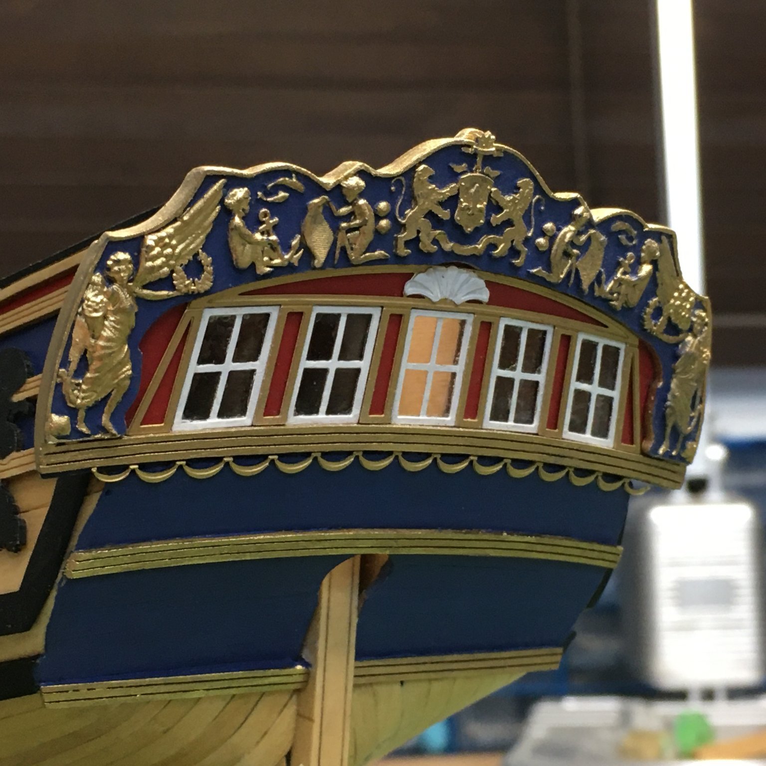
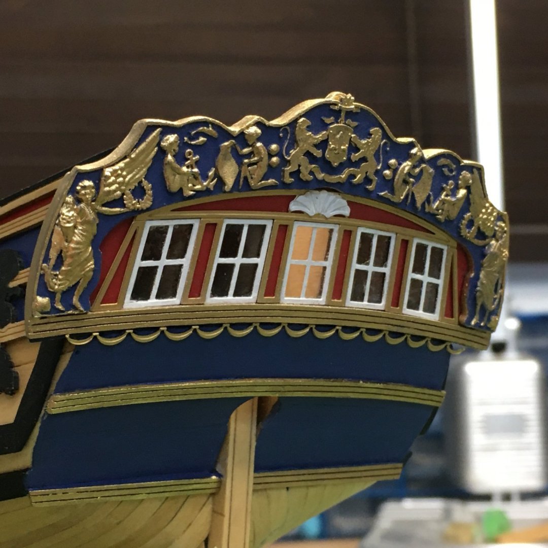
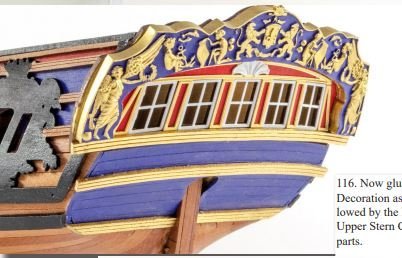
Stern decoration completed Once I'd sorted out the self-inflicted problem with the fascia the rest of the stern decoration went smoothly. There were only two points of particular interest. The first involved gluing the swags beneath the window. This was a very fine and delicate piece of photoetch, and I was worried that it would be hard to apply any sort of glue without spoiling the paintwork. In the end I remember that matte medium can be used as an adhesive. I originally bought this product to try as an alternative to dilute pva or shellac for use in rigging, but as an adhesive it dries quickly and invisibly. It worked well - here's the swag in place, along with the rest of the stern decoration. I had considered floor polish for sticking PE as discussed in other Duchess logs, but I may stick with matte medium if it continues to work as well as this. As always, close-ups show the need for some touching up, but nothing major. The other point of note was trying to disguise the join between the stern fascia and the cast resin decoration. In the manual the resin is painted gold and the wood left: This looks neat but I wanted to see if I could make the capping slightly more realistic by eliminating the step between the tops of the two components and painting the whole cap gold. I considered but dismissed the idea of moulding a strip to cap the two pieces, and in the end went for filler. Here's the result of the first attempt: Perhaps another go at smooth the cap and repainting, but I'm pleased with the result so far. Derek

- 345 replies
-
- 15
-
-
- Duchess Of Kingston
- Vanguard Models
- (and 1 more)
-
I'm just catching up with your log Glenn and I'm jealous already! That hull looks awesome. I'm also jealous of your workshop - how do you keep it so clean and tidy? Even when I've just tidied mine it looks 10 times worse than yours. One day I'll post pictures to prove it. Anyway, I'll follow your log with great interest from now on - it may spur me on to re-start my Winchelsea. Derek
- 840 replies
-
- 5
-
-
- winchelsea
- Syren Ship Model Company
- (and 1 more)
-
Sterns always seem to be tricky to get right. Yours is looking fine so far - just make sure you don't make the same mistake as me when you come to fit the stern fascia. I soaked the fascia in hot water to bend it to shape and let it dry, after which it seemed to fit fine. It was only when I tried to fit the photo-etch decoration to it that I found it had expanded and was 3mm too wide - more than enough to make it unrecoverable at this scale. See here for how I got out of it, and how I used hot air bending to avoid the same mistake. Sorry if this is teaching Granny to suck eggs! Derek
-
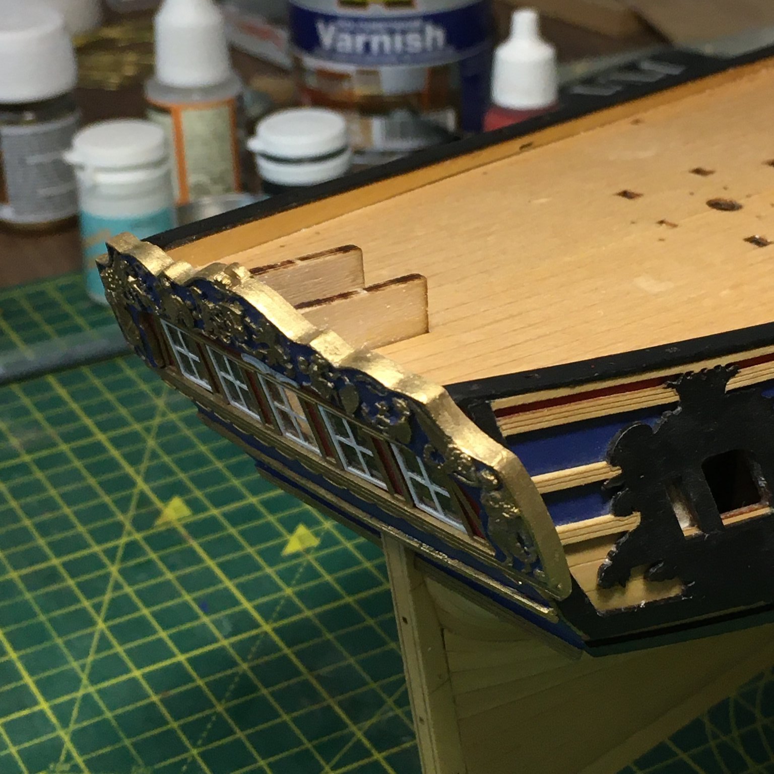
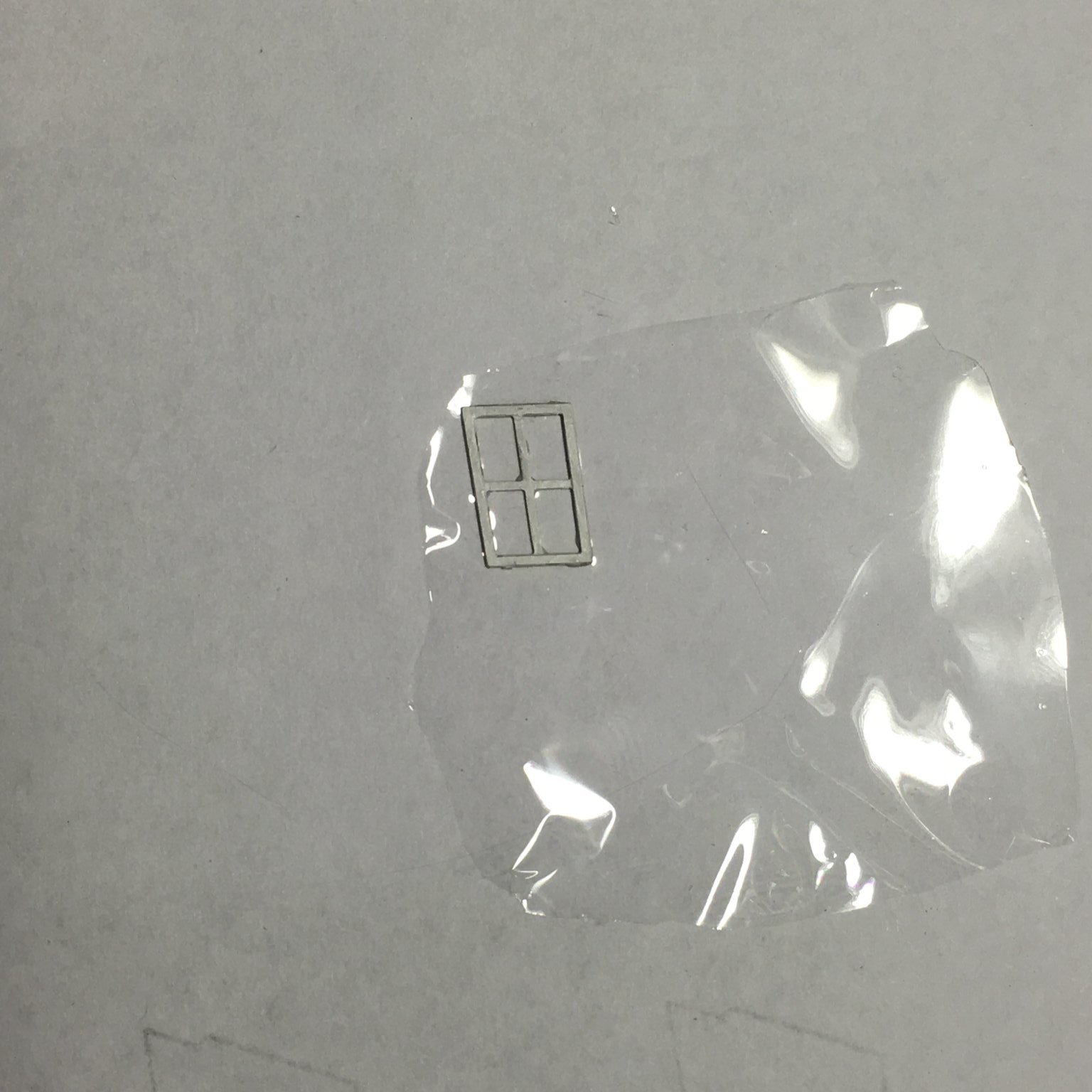
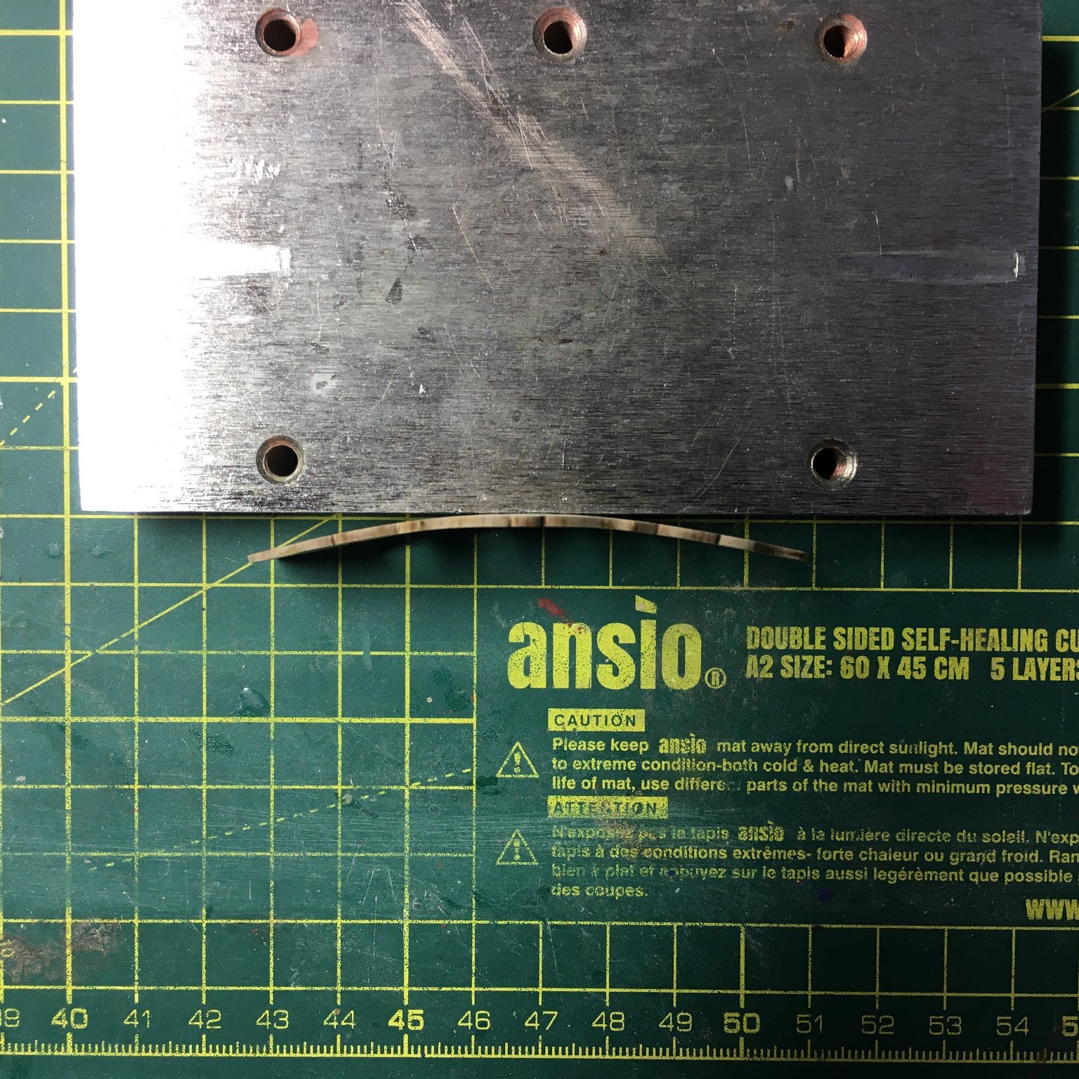
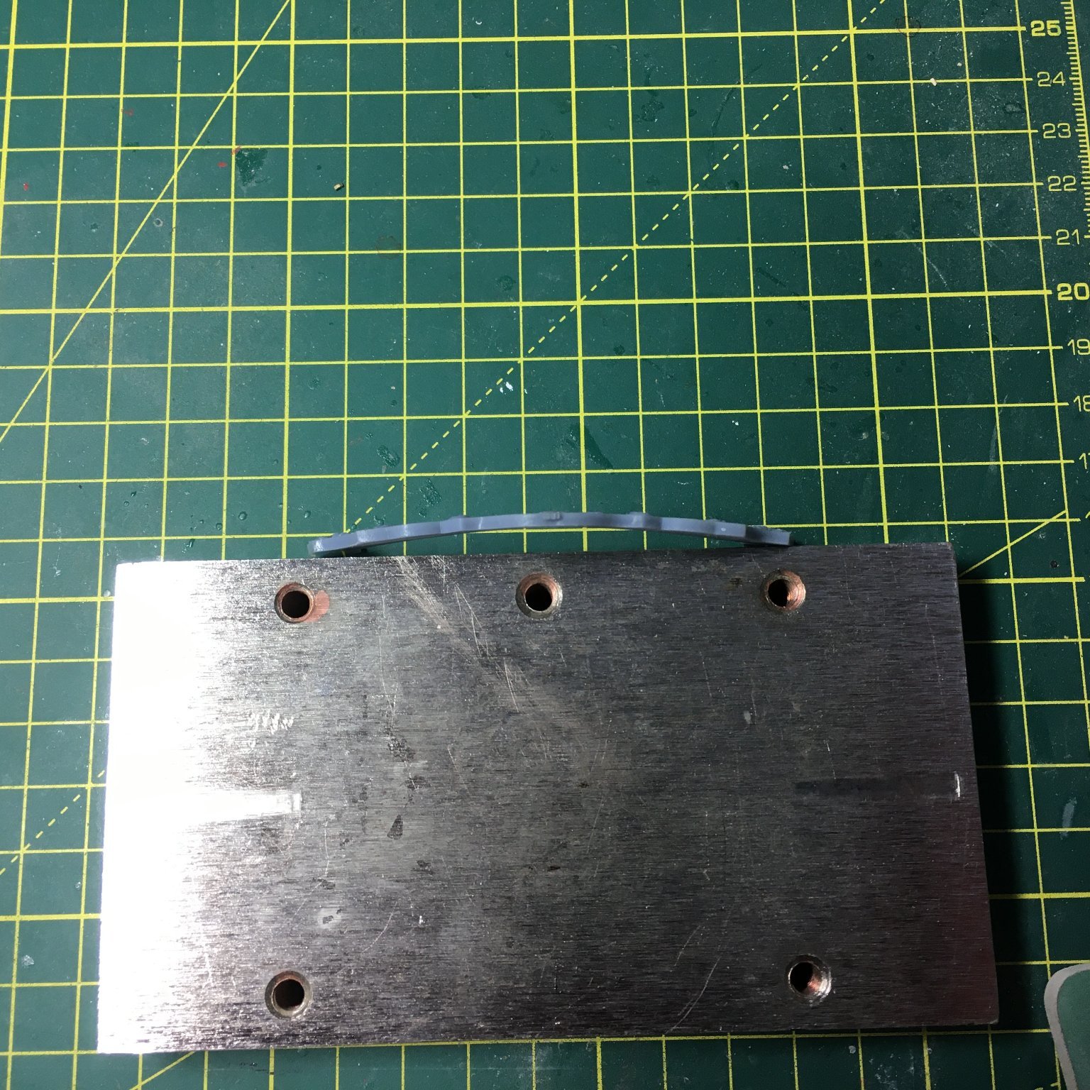
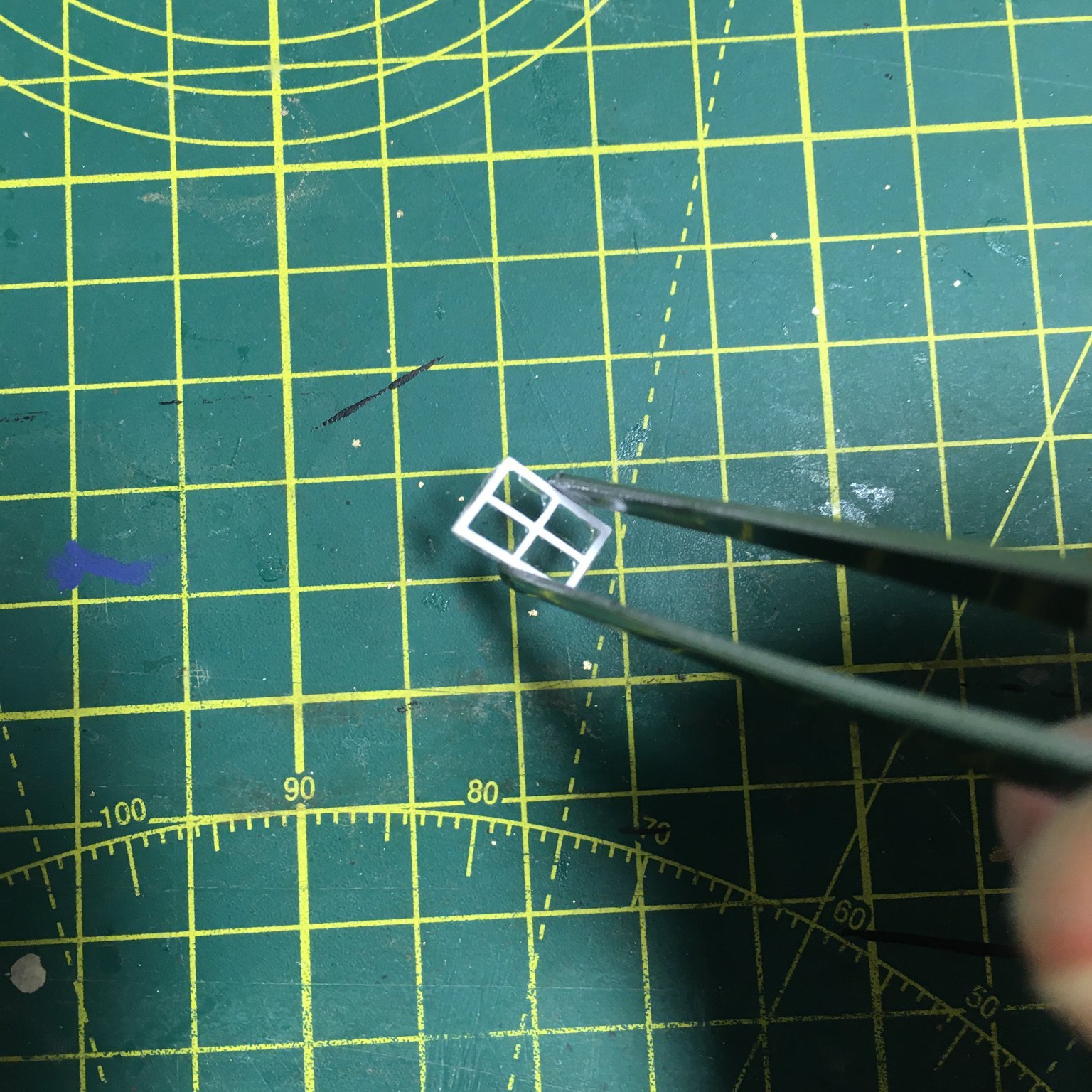
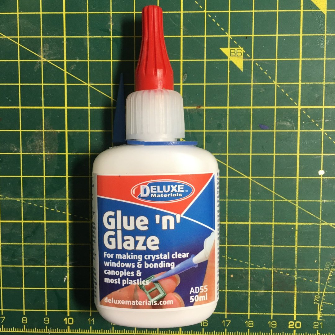
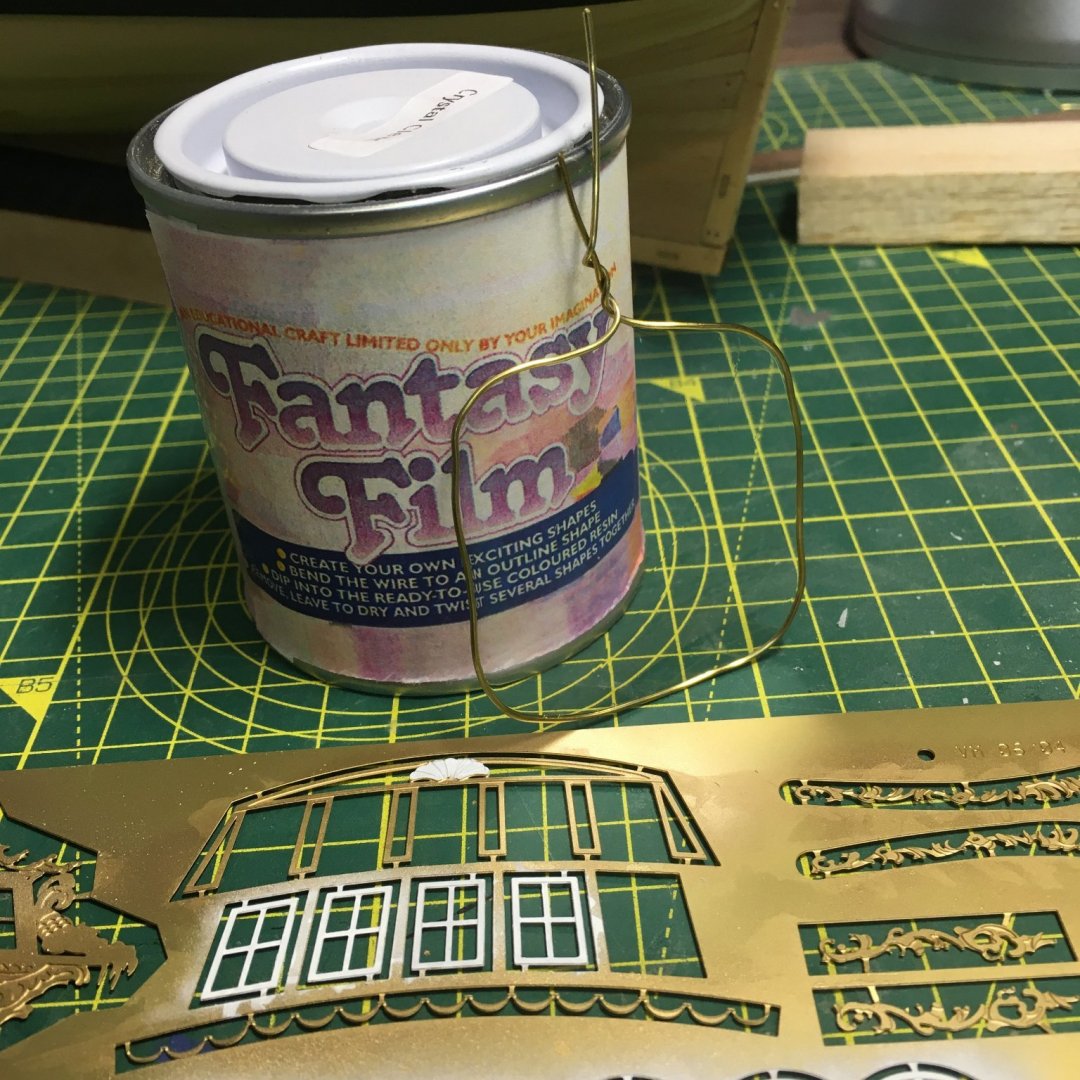
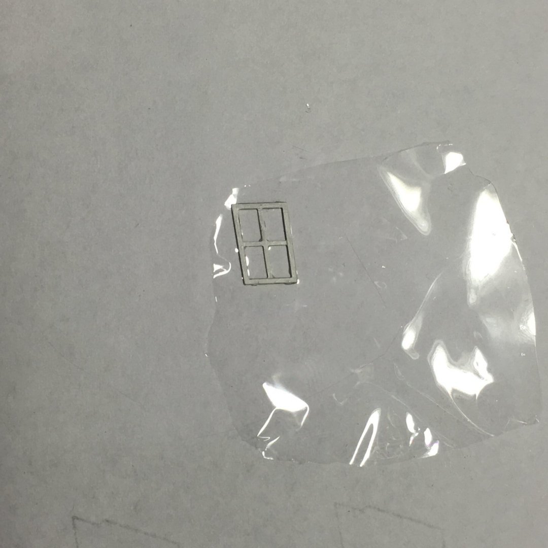
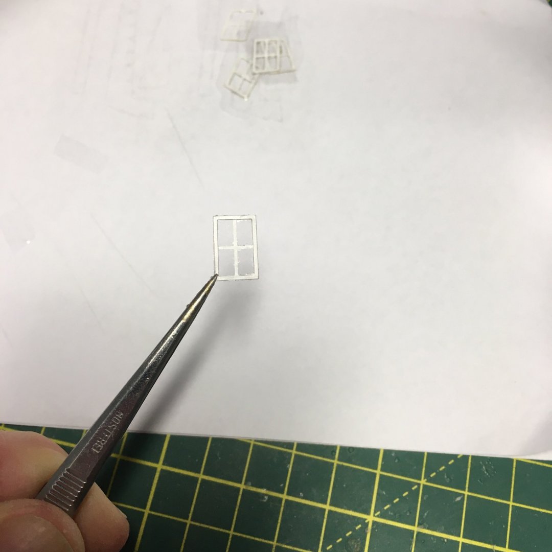
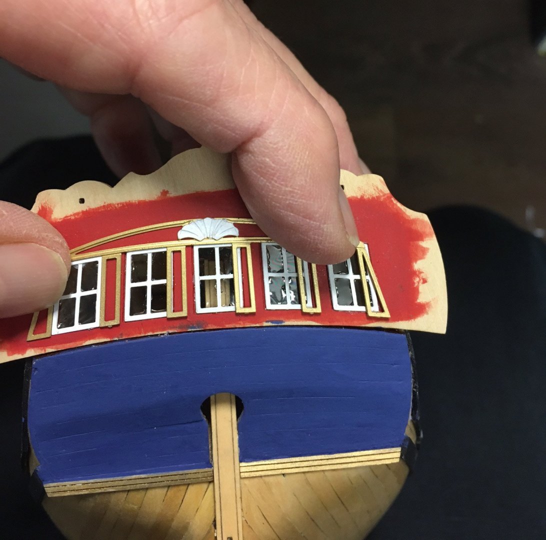
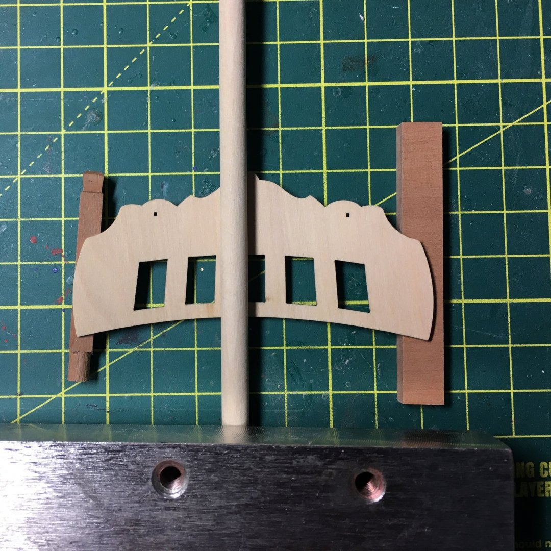
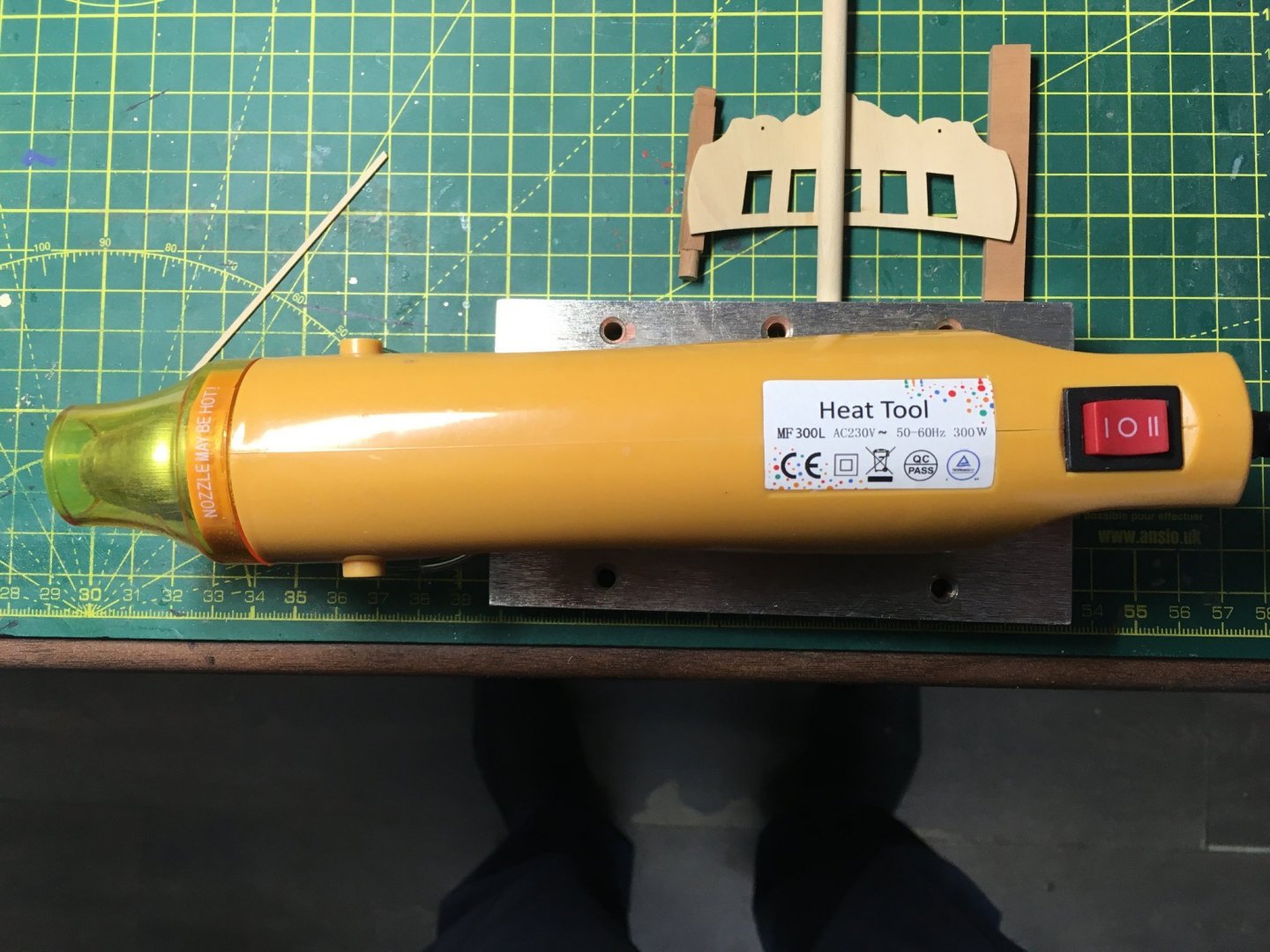
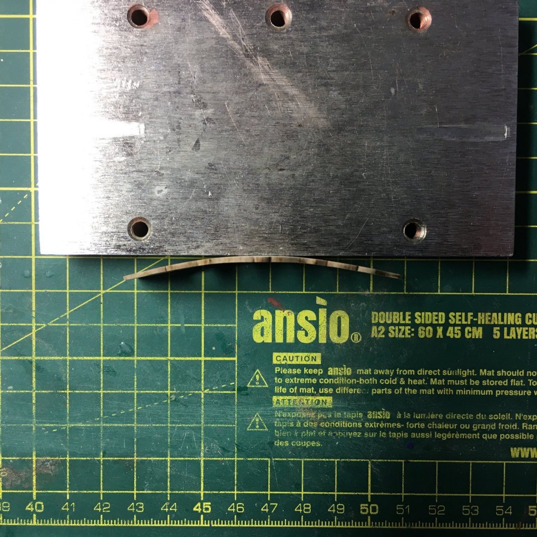
Glazing experiments and (almost) a disaster As always, many thanks for the kind comments and likes. I decided to glaze the windows but wanted something a bit more realistic than clear acetate. First I tried Glue 'n Glaze... ...a product used by railway modelers and others to simulate glazing. This looks like PVA but dries clear, and is applied using a cocktail stick or similar to spread the liquid across the window opening. I found it very difficult to photograph the result, so you'll just have to take my word that it didn't look right - too thick and uneven, even for 18th century glass. Next, my wife told me about a product called Fantasy Film, used by crafters to produce decorative effects. The idea is to twist a copper wire into a shape such as a leaf, dip it in the liquid, pull it out and it dries to a very thin translucent film. Obviously for a leaf or petal you would use coloured film, but I managed to get hold of the clear version to try it out as a glazing material. When I dipped a window the result was almost OK. The problem is the liquid is quite thick and dries very fast. No matter how quickly I pulled it out of the liquid it didn't finish flowing off the bottom edge before it solidified, leaving an unsightly blob in the bottom two lights. The liquid also solidified around the glazing bars making them too thick. Long story short, I came up with two methods that seem to work well. The first involves using a loop of brass wire to make a large sheet of film, laying a window on the film with a tiny smear of Glue 'n Glaze (which also acts as a clear glue) and trimming once dry: Difficult to see the final result in the photo, but I felt this looked more realistic. The film is crystal clear but not dead flat, so it gives the impression of old glass. The second method involved holding a window in a pair of large tweezers in such a way that I could hold it flat against the surface of the liquid, just touching the back edge and pulling it away again. I couldn't photograph this process but here's how I held the windows: Held vertically to dry, this left a film in each of the four lights of the window without coating the front of the glazing bars and without the unsightly blobs I got when dipping the whole window into the liquid. On balance I prefer this method as it doesn't need as many steps. The Disaster (almost!) The five windows fitted in the stern fascia without a hitch. It was when I came to attach the photo etch window surround that I came unstuck - it didn't fit: With the left hand edge lined up, the rest of the surround was way off. I checked the PE against the plans and it was spot on, whereas the stern fascia was 3mm wider than it should have been. I realised belatedly that I had soaked the fascia in hot water too long and, although I'd waited until it was dry it never shrank back to the original width. With most kit makers I'd have had no option but to make my own replacement, but now that Chris has his own laser machine he was able to supply me with a replacement in the next post and at minimal cost. Chris was also kind enough to send me a sample of the stern decoration from his new 3D printer. More of that anon. First, I wanted to bend the new stern fascia without expanding it so this time I tried dry heat, using an arrangement of blocks and a weight to hold it in place. The blocks were 5mm thick which I reckoned would give the right degree of curvature, with the fascia held down by a rod with a weight on the end. The second picture shows the hot air gun: I put the gun on the hottest setting and aimed it at the fascia for about 30 seconds then left it to cool. The method worked well, leaving a permanent curve. I tried the same method on the stern decoration and found it worked equally well on resin: I'll use dry heat as much as possible from now on. Finally, I painted the new stern decoration Chris had supplied to compare it with the original: The new one is at the top. Those with a microscope might detect a difference, but I think Chris is on to another winner here. Next, I'm looking forward to finishing off the stern. Derek

- 345 replies
-
- 13
-
-
- Duchess Of Kingston
- Vanguard Models
- (and 1 more)
-
Well done. It’s worth taking care to get everything right at this stage. I managed to break off all but one of those tiny pieces. I’m saving them until I fit the decoration as the PE surrounding the windows will cover them. One tip if you have to make tiny parts is to shape them in to the end of a longer piece of wood. This gives you something to hold until you’re happy with the shape, then just cut it off. Derek
-
Sorry Glenn, my mistake. I got confused because we'd been discussing turning tools and I had my mind on the lathe. I hadn't realised you were thinking of drilling the holes. I used the micro drilling attachment and the V block in a mini mill. Although the mini is only one class up from a micro mill it's a much bigger beast, weighing in at over 200 lbs and with interchangeable chuck and collets. The same mill will be available in the States - they're all made in the same factory in China and rebranded in the West. Here it is fitted with a chuck: If Santa's in a good mood it might be worth considering. However you can use the micro drill attachment in other things with a chuck - for example a benchtop pillar drill like this: If you've not got one they're much more reasonably priced and good for other jobs around the house.


- 345 replies
-
- 4
-
-
- Duchess Of Kingston
- Vanguard Models
- (and 1 more)
-
Not sure why you'd want a chuck on the mill? You should be able to hold all the tools you need using collets. Or have I misunderstood? I did the balustrades on the lathe. I've put a CNC machine on my Christmas list 'cos I'm greedy. Doubt I'll get it though 😒
-
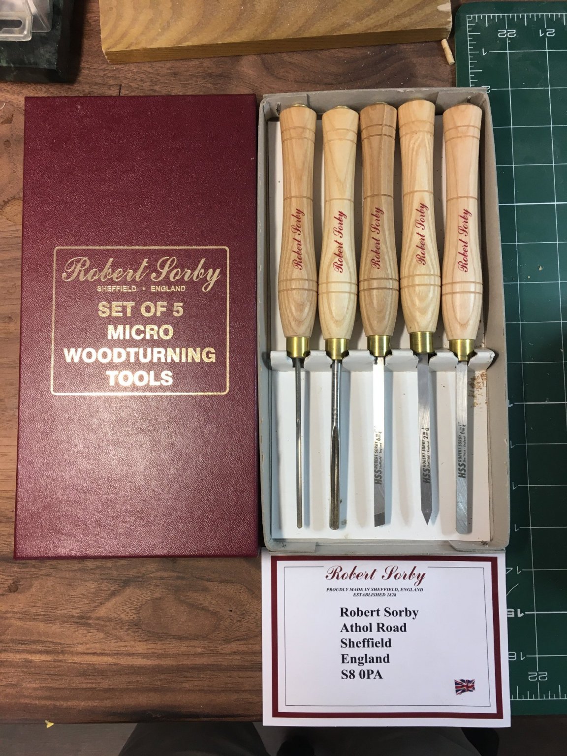
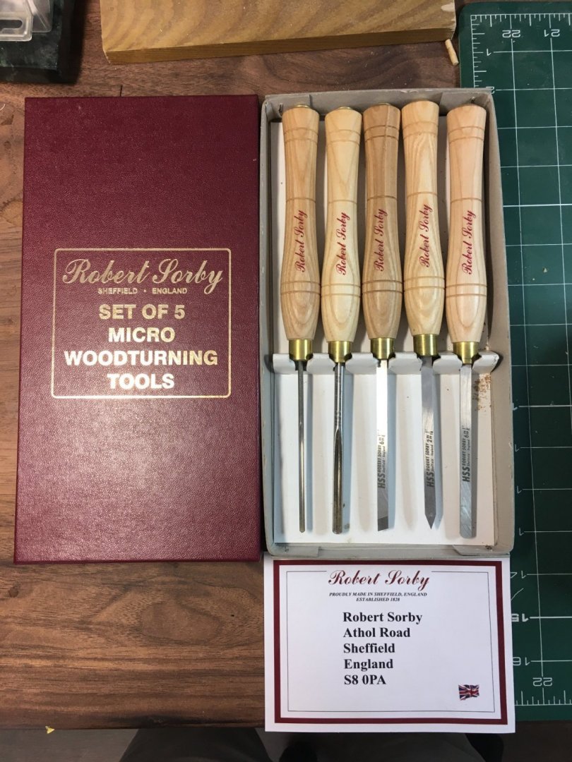
Thanks James, Rusty & Glenn. Yours still looks fine Rusty. I just enjoy playing around and problem solving - and every time I look at your log I half regret not planking my own deck like you did. I use these woodturning tools - the gouge to get the right diameter and the rough shape, the knife edge to mark out the main sections of the piece then files for the final shaping: The next picture shows a balustrade with the sections marked out and roughed to shape, and prior to filing: Ordinary wood turning tools are easy to come by, but for tiny pieces (2.8mm diameter in this case) these smaller tools are essential. I'm not sure this brand is available in the US, but I'm sure there will be alternatives if you search for micro woodturning tools. Here's a link to my Speedy log where I first started using them to make anchor buoys. Hope this helps. And by the way, I've already got a shelf in my workshop labelled 'things Glenn made me buy' 😁 Derek
- 345 replies
-
- 7
-
-
-
- Duchess Of Kingston
- Vanguard Models
- (and 1 more)
-
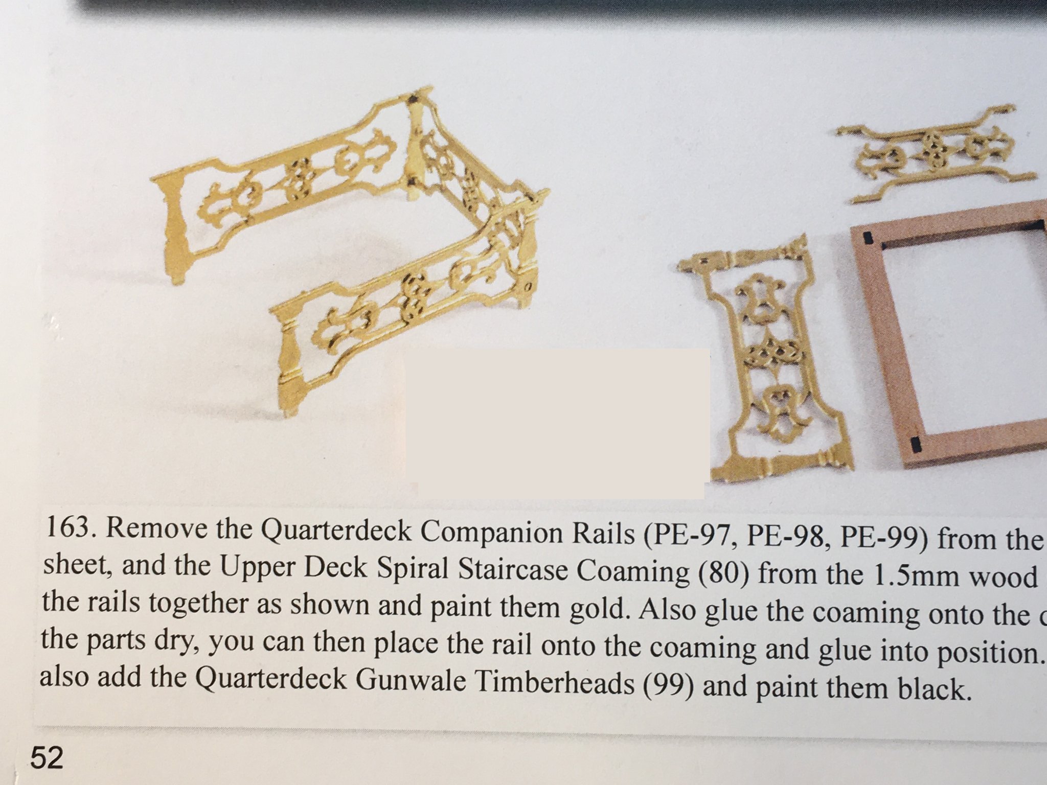
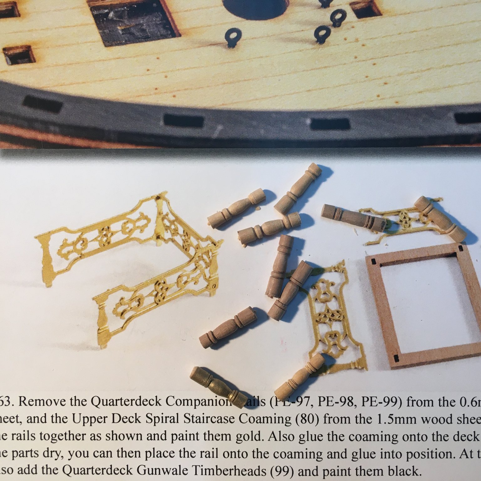
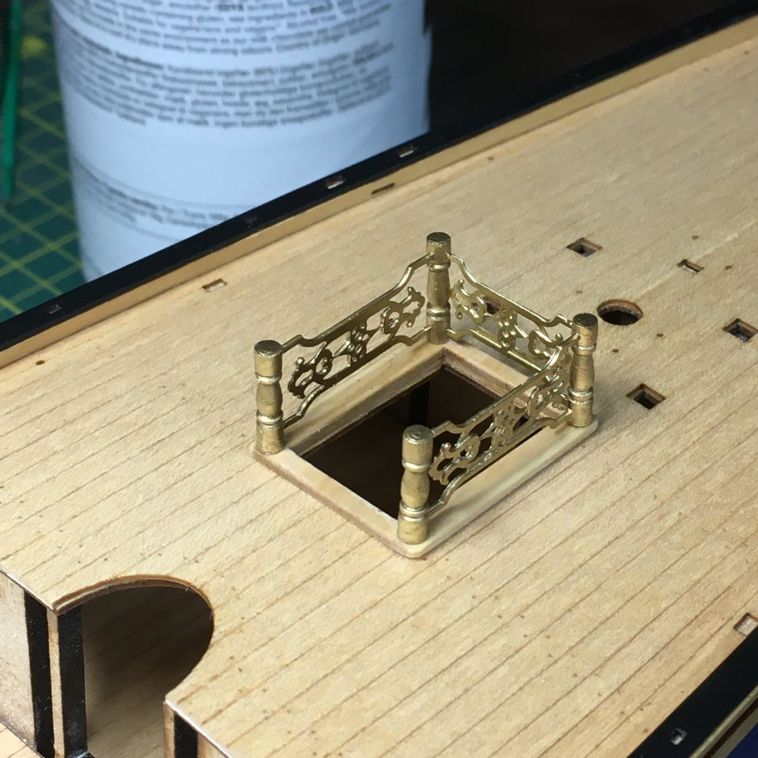
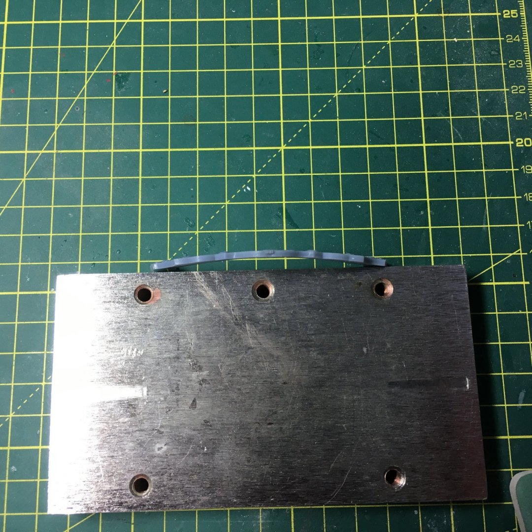
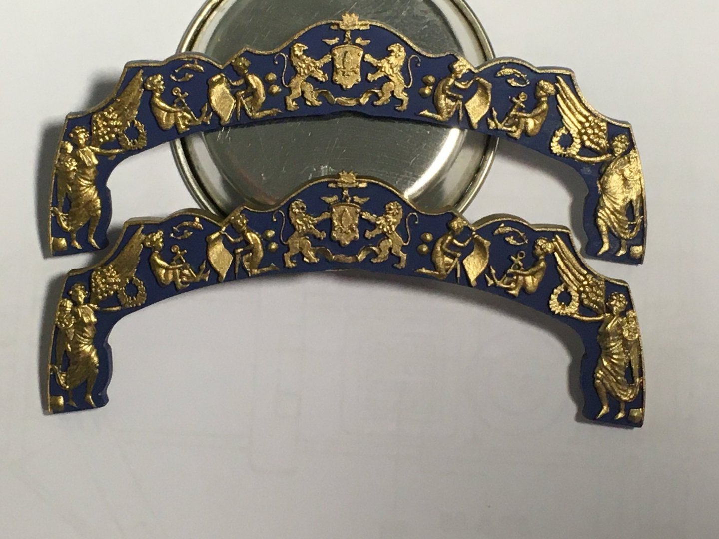
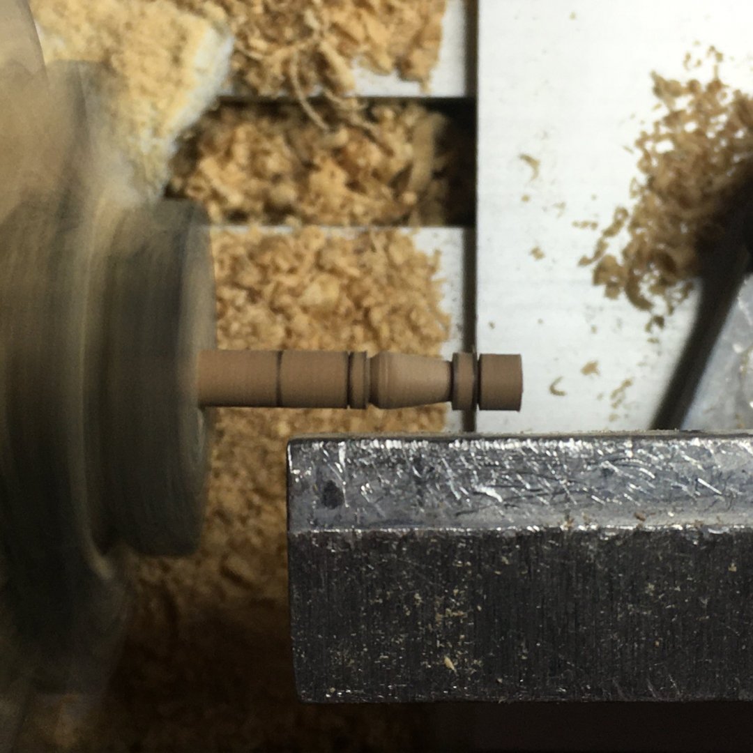
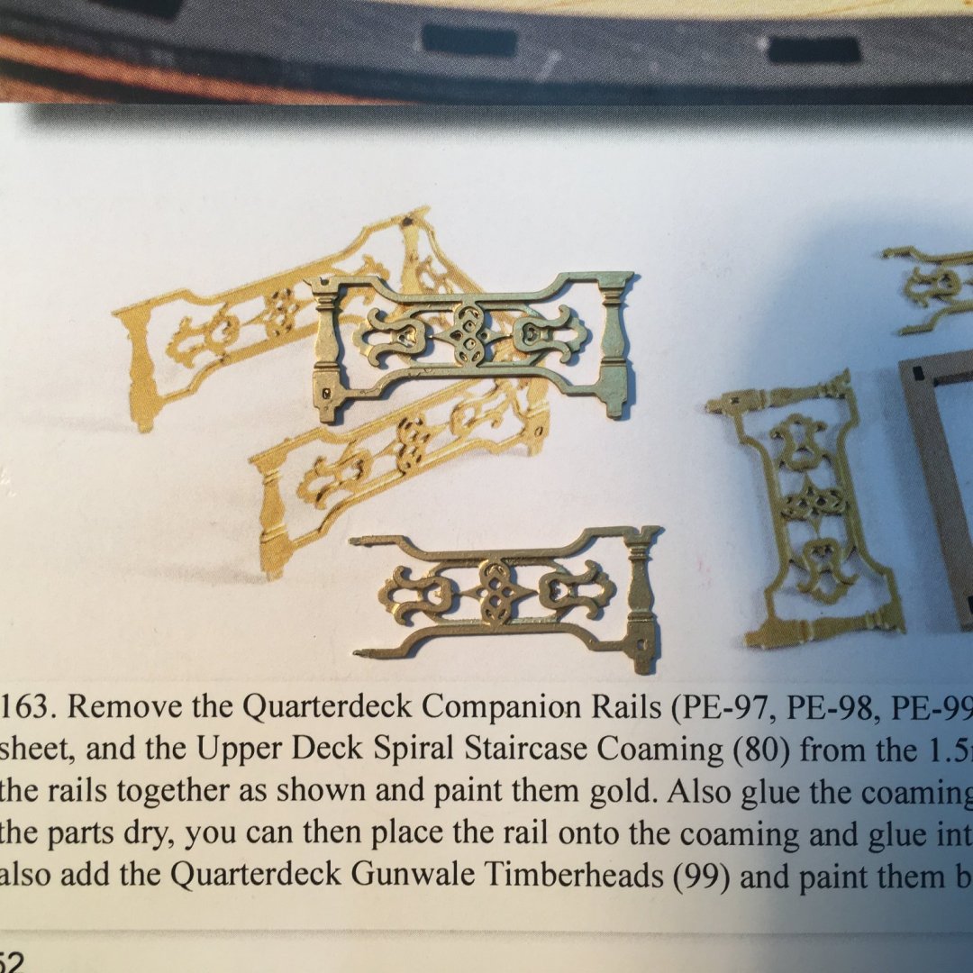
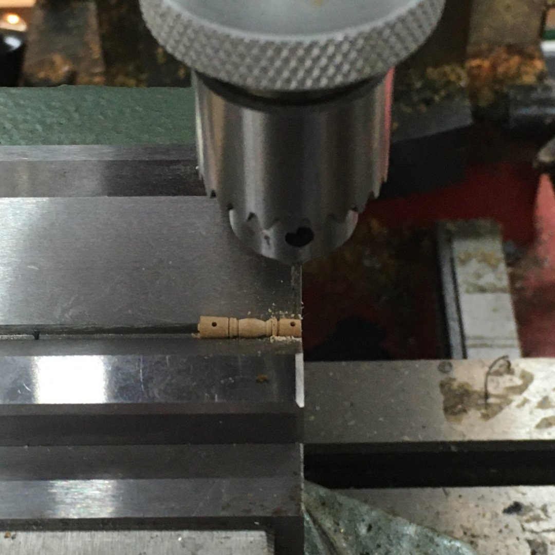
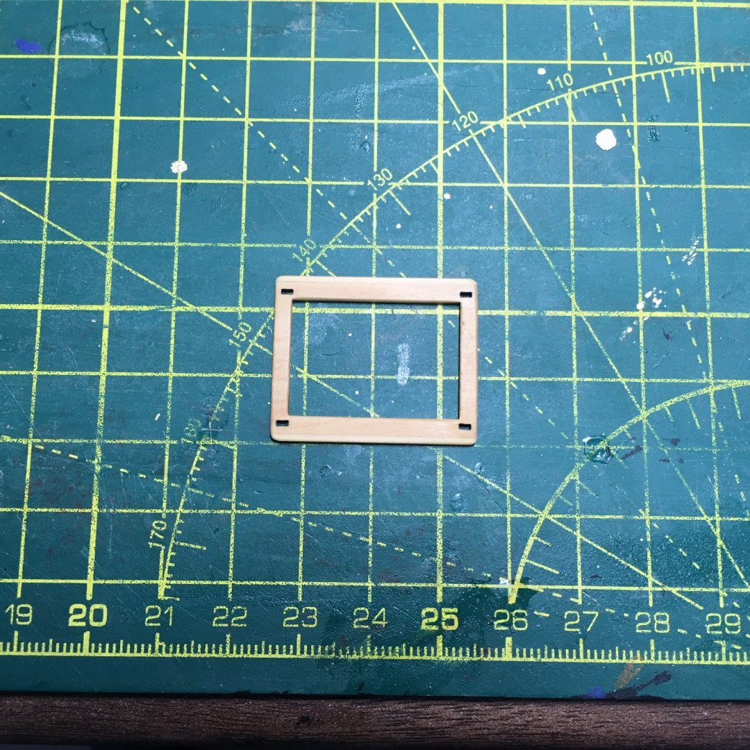
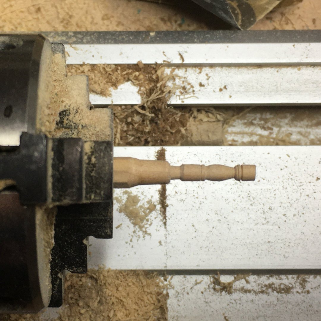
Quarterdeck Companion Rails Having taken a break from the stern decoration by working on some odd jobs such as the curved stairs, I was tempted to tackle the quarterdeck companion rails. These sit at the top of the stairs and have always niggled me since I first saw that they were made entirely from photo-etch. The PE makes beautifully decorative railings, but I felt the four balustrades looked flat and unnatural, albeit well detailed: I decided to have a go at turning my own balustrades on the Proxxon wood lathe. I had a spare castello boxwood mast left over from Speedy which I turned down to just under 3mm. Then, using the PE as a template I started practicing with various turning tools and files: I made quite a few before I had four that passed muster. Here are the rejects! The next job was to cut the balustrades off the PE using a jeweler's piercing saw, leaving enough of a peg on the railings to fasten into the new balustrades: To drill 0.6mm holes in the balustrades accurately I used a technique I described here in my Speedy log, employing a vee block and a micro drill attachment in my mini mill: Next I prepared the coaming, sanding off the char and rounding off the sharp edges. The only slight change here was to the width. Because the new balustrades are thicker than the photoetch I had to glue strips of 0.5 mm boxwood to the long edges: With the balustrades and PE glued up, painted and stuck to the coaming here's the end result: This little side project has recharged my batteries and I'm ready to start on the hull decoration again. Derek


- 345 replies
-
- 16
-
-

-
- Duchess Of Kingston
- Vanguard Models
- (and 1 more)
-
The Kell guide handles the 1/8" Veritas chisel very well. See here. Derek