


druxey
-
Posts
12,491 -
Joined
-
Last visited
Reputation Activity
-

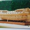 druxey got a reaction from mij in HMS Sussex by mij - Scale 1:48
Congratulations on your second start! I hope you'll be happy with the cherry this time.
-
 druxey reacted to mij in HMS Sussex by mij - Scale 1:48
Cherry ready for the bandsaw
The cherry cut and ready to be milled.
It was worth the time and effort.
Tulip on the left and Cherry on the right
Start of the new build in cherry.
In the back ground is the one made from tulip.
-
-
druxey reacted to Remcohe in HMS Kingfisher 1770 by Remcohe - 1/48 - English 14-Gun Sloop - POF
Thanks guys.
Greg the pins are easy to make, I think they rank amongst the top 10 most used tools in my build.
Ben, with my scroll saw they were relative easy to make and there were no remakes :-)
I couldn't find an appropriated sized piece of brass for the iron knee so I made it from boxwood and tinted it black with Fiebing's leather paint
I'm also doing lot's of mortice cutting for the remaining carlings and ledges.
A little off topic, but it was time to make a better storage for my chisels. They used to wander over my bench with the tip protected by a little piece of isolation foam. This was a nice little project, keeps them safe and organized
Remco
-
druxey reacted to shipmodel in Queen Anne's Revenge 1710 by shipmodel - FINISHED - 1/36 scale
Thanks for all the nice compliments.
Michael - I will trade some of my carving skills for your metalworking expertise. I just finished reading your log of the Bristol cutter and was blown away.
Ken - yes, the jaw is the major problem, but the width of the eye sockets also seemed too broad. Here is the face after narrowing. The lion is coming along nicely, but has a ways to go. If my artistic skills are up to it, I want to get a ferocious expression, but that may be hoping for too much.
After putting the lion to bed for a while, the next independent pieces that I turned to were the mast tops. By 1710 in France they were circular but without the earlier raised rim. They are built with the usual overlapping plank construction, a flat rim and radial cleats. Here are Budriot’s plans, which are almost identical to Lees’ and Marquhardt’s. This is the main top, but the fore is identical, other than being scaled down just a fraction. The mizzen top is smaller, but the construction method for all three is identical.
To build them, the first piece to be made was the square filler piece. It is just a piece of 1/8” thick scrap, sized to the lubber’s hole on the plans. The cryptic symbol on this one is left over from its use as a jig for a previous model. I cut this carefully on the Preac, as it will guide the rest of the construction.
The planks are 1mm thick birch, cut to width and long enough to span the diameter of the top. On the real ship they would have been cut thick then carved down to make the lap joints, leaving a raised portion in the center. Instead, I took a piece of the planking and cut sections the length of one side of the filler guide. These were then glued to the center of the planks with the edges matched up. When the glue was dry one edge was colored with a black marker. A completed one is just above the filler guide piece.
The cleats in the lower left are mass produced since the fore and main tops take 16 each and the mizzen top takes 12. I cut a rectangle of 1mm cherry sheet with the grain going in the short dimension. Then I glued another strip on top of one edge with an overhang equal to the width of the rim with the grain also running in the short direction. Now I could part off 1/16” wide cleats with a narrow blade in the table saw until I ran out of material. The cleats are left raw at this point and will be shaped and tapered later.
To start the platform construction, four of the lap planks are positioned around the filler guide. Two of them (top/bottom) have the thick section turned up and the other two (left/right) have the section facing down. They are glued at their overlaps and clamped tightly around the filler guide.
When they are solid it is easy to lay in the other down facing planks and glue them to the underneath planks and to each other. After the clamps are removed the platform was flipped over and the remaining planks were glued across the first sets of planks.
The center of the filler piece was located and the outer perimeter of the top was drawn with a compass. This was cut close on the band saw and left rough, to be taken down to the line on a disc sander after the rim is installed.
With the compass still set for the perimeter size, an arc was drawn on a rectangle of the cherry sheet, this time with the grain running the long way. The compass was closed the width of the rim and a second curve was drawn inside the first but with the same center. Three more pieces of cherry were stacked under the first and glued together at the upper corners and lower center only, not where the rim pieces will come from.
The inside curve was cut on the band saw then smoothed to the line with a sanding drum in the drill press. The outer curve was cut large, to be sanded down after installation on the platform. After completing the second cut the pieces separated automatically. The rim pieces were cut to one quarter of the circumference of the platform using the plans to make the initial cuts, the fine tuning being done during assembly.
With the platform, rims and cleats made, I assembled them with neutral pH PVA glue. Care has to be taken to see that the cleats are equally spaced and the rim pieces match up to each other, but otherwise construction is pretty straightforward.
The shafts of the cleats were made overlong so their tails extended into the lubber’s hole. These tails were clipped off and the shafts tapered from the rim to the hole with a flap-wheel sander.
All of the corners and edges were cleaned up and rounded with a sanding stick then the top was given its first coat of finish.
Here I used Floquil clear flat, but with a few drops of my stain mixture (50% Natural, 25% Cherry, 25% Early American) added. The finish enhanced the color of the cherry while the light stain brought the tone and hue of the birch into the same color family. It even slightly enhanced the grain of the birch, as if it were older wood. This is exactly the effect that I was looking for. I think that I will be using this color palette a lot as the build continues.
The trestletrees and crosstrees were cut to length from 3mm x 6mm pear. I used the Preac to cut the notches in the trestletrees to accept the crosstrees. Tapers were sanded on all eight arms as shown on the plans, then they were installed on the underside of the platforms.
Holes for the crowsfoot lines were drilled through the forward rim. I spaced them a bit closer together at the center to account for the anticipated narrowing effect as the top curves away from the euphroe. I’ll see how that works out when it is rigged.
The elongated holes for the upper deadeye strops were roughly cut by drilling two holes side by side then using the drill bit to nibble out the wood between them.
Finally, I indicated the nails that hold the two layers of planking together where they overlap. As with the boats, these were indicated by drilling shallow holes with a #80 (0.012”) drill. A wash of stain mix was flooded over the holes and immediately wiped off. It darkened the holes without changing the color of the planks. This is a technique that I will use again as well.
There will be additional holes to mount a number of blocks under the tops, but I have not studied the rigging plan enough yet to locate them. For now, here are the six tops ready for storage till needed.
I'm up in the country this weekend, so hopefully I will soon have some progress to share on the hulls.
Dan
-
druxey reacted to trippwj in Young America 1853 by EdT - FINISHED - extreme clipper
Ed -
Thought you may be interested in how the New York Register of Shipping showed the framing of ships in 1857 & 1858. No specific ship named. Mystic Seaport has many of the volumes scanned and available to view at http://library.mysticseaport.org/initiative/ShipRegisterList.cfm
This is from the inaugural 1857 issue.
These are from 1858
-
druxey reacted to dvm27 in HMS Bellona 1760 by SJSoane - Scale 1:64 - English 74-gun - as designed
Brilliant milling work, Mark. The Starrett wiggler would have saved me hours of fine tuning on my last project and I shall now get one. Love those perfect carling mortises also.
-
druxey reacted to gjdale in HMS Bellona 1760 by SJSoane - Scale 1:64 - English 74-gun - as designed
Very, VERY, nicely done Mark. Take a bow!
-
druxey reacted to SJSoane in HMS Bellona 1760 by SJSoane - Scale 1:64 - English 74-gun - as designed
HI everyone,
Druxey, remco, EdT, Michael, blue ensign, spencerC, thank you for your kind comments. And many apologies for not replying sooner; work is really getting in the way of the shipyard these days!
After finishing up around the main mast, I sat down one day to finish up the mortises in the beams for carlings. I was inspired by Gaetan, who advised me that doing the same thing over and over, and in a logical order, is efficient, meditative, and it improves one's skills. So I told myself I was not leaving the shop until the remaining mortises were cut. It was hours later, but very satisfying to see all of these after a number of years of looking at the deck without mortises. Gaetan was absolutely right in his advice. i processed each step on all beams, then went back to the first for the next step. It build a great rhythm.
I then turned my attention to the step for the main capstan. You will see in the photo of the original Admiralty drawing that this was very cryptic. How does a circle sit on the beams, and how does one plank up to the circle? I then came across a photo of the Ajax cut away model, showing the entire gun deck. It showed this step as a raised surface in a rectangular plank. After reviewing Steel, I decided that it was really a central, thicker plank, with thinner planks on either side to make up the width across the two central carlings. You can see the dotted line of the three planks in the Admiralty drawing. The projection at the front of the circle is to provide a surface for the pawls, which pivot from the fore edge of the projection and can be kicked under the capstan when wishing to stop rotation either way (another fun part to make some day).
I also remembered from David Antscherl's book that the top surface of the capstan step would have to be parallel to the keel, not parallel to the deck. This is because the capstan turns on an axis perpendicular to the keel, and the aft side would be higher off the deck than the fore side because the deck slopes at this point. Then it made sense that the circle would provide the surface parallel to the keel, and the remainder of the step would be flush with the decking and therefore parallel with the deck, to avoid places to trip when working the capstan. Very ingenious design, when you finally figure out what they were doing.
I had fun with the mill making this. First, you see the step sitting in a vise on the tilting table, having one surface milled down at 1 ½ degrees to match the difference between the deck angle and a line parallel to the keel. Then you see the rotating table, with the step mounted on top. I first used a Starrett wiggler on the central hole of the rotating table to align it with the mill spindle. Then I clamped the step on top, using a Starrett wiggler to locate the center of the step circle also under the mill spindle. I then used a mill cutter to cut a perfect circle around the edge, leaving a flat base with a raised circle at the 1 ½ degree angle. I used chisels to clean up the serpentine curve on either side at the fore end.
I stole the capstan from midships for the photos. I now need to build the second capstan....
Best wishes,
Mark
-
 druxey got a reaction from Trussben in ECHO by Trussben - FINISHED - 1:48 - cross-section
Nice presentation in the case, Ben. Congratulations on completing your 'fully framed' cross-section!
-
druxey reacted to Trussben in ECHO by Trussben - FINISHED - 1:48 - cross-section
Final Pictures of my Echo completed and in its final resting place.
I have enjoyed immensly this build and want to say a big thanks to Greg and David for making this available
and for the great plans, instructions and help.
Now to get ready for the Pegasus
ben
-
 druxey got a reaction from DORIS in ROYAL CAROLINE 1749 by Doris - 1:40 - CARD
Thank you, Anja. Please also give Doris best wishes and a speedy return!
-
druxey reacted to EdT in Young America 1853 by EdT - FINISHED - extreme clipper
Young America - extreme clipper 1853
Part 22 – Cant Frame Scores
American Clipper Note: In a departure from the historical notes on the stirring adventures of these ships in service, I thought it would be a good idea to comment on some construction aspects as well. Since the forward framing is set to begin on the model, some description of that might be appropriate.
The bulk of the transverse hull framing on these ships – and most ships – consisted of full breadth “square frames” whose lower timbers rested on and were bolted through the keel. As the forward (or aft) end of the ship was approached and the v-shape of the floor timbers that crossed the keel became more acute, a point would be reached where naturally grown “compass timber” could not be found to make these pieces. At that point – on these ships – “half frames” were installed. These were still square to the keel, but were made in separate assemblies for each side of the ship and were bolted horizontally through each other and the vertical deadwood/keelson structure – the backbone of the hull. Further forward, as the bevels on these frames became more pronounced, it would no longer be possible to bolt the sections of each half frame pair together with bolts “normal” or at a right angle to the face of the frame, without the bolt being exposed through the beveled side. At this point “cant frames” were used to complete the bow (or stern) framing. These were also bolted to the deadwood but were angled – canted – forward to reduce their bevel and allow the pairs to be bolted together securely. Since every ship had a different shape and since timber availability varied, it seems likely that these break points were set for each ship in the mold loft as the frame patterns were drawn out and timber supplies known.
I applied this assumption in lofting the frames for the Young America model.
Before starting work on the next frames to be installed – the forward half-frames – the “scores” for the cant frames needed to be cut while there was still enough room to do this. These scores provided important support to the angled cant frames by allowing them to be inset into the keelson/deadwood – rather than depending on bolts alone.
The vertical joint faces of each half-frame and the cant frame extend up from the bearding line to the cutting down line. The bearding line defines the point at each frame where the frame profile narrows down to the face of the 16” wide keelson/deadwood. The cutting down line defines the upper edge of the inboard faces of the frames at the keelson/deadwood.
The first picture shows a template - made from the drawing - being used to trace the bearding line on the model.
A similar template was used to trace the cutting down line above this. The next picture shows the vertical lines of the scores being marked using a Plexiglas square made to slide clear of the keel retaining strips on the base board.
These lines define the extent of each of the five cant frame joint faces – the area to be inset. The next picture shows the first score on the starboard side cut out.
Since I plan to plank the starboard side of the model, I started this risky chiseling process on that side for practice. Planking is a great way to hide framing mistakes.
I will not describe the full process here, but the next few pictures show it generally. In the first picture the vertical lines are being scored with a knife using very light cuts.
In the next picture, a chisel is being used to cut into the deadwood at the bottom – just above the bearding line. The line just above the chisel is the joint line between the apron and the deadwood.
The score itself was then pared out with various small chisels. The next picture shows some of that work in progress.
The last picture shows three of the five cant frame scores essentially finished. Two more to go – on this side.
Although it was more difficult to manage this work in place, I did it this way because the overall hull assembly is still quite weak and I did not want to risk setting it up on the workbench for that reason.
Next: on to the half frames.
Ed
-
druxey reacted to Tigerdvr in How to fasten a line to a belaying pin on a real ship and model.
Thanks for the post and video. It will be a great help with my Syren project.
Regards, Harley
-
druxey reacted to Modeler12 in How to fasten a line to a belaying pin on a real ship and model.
When I boarded a square rigged sailing ship, I asked one of the crew members to show me how to belay a line. The video below shows how this was done and how I adapted the procedure for my modeling. The technique is updated from an earlier video I showed, and now includes how I made the coils shown in the picture below.
The nice thing with this method is that now I don't coat the whole line with glue, only the top of the loop. This allows me to adjust the lay of the coil when installing it on the model. Since each coil is made individually, it takes me about five minutes per coil. But notice the difference between the 'old' coils (top left in the picture below) and the current ones.
Here is the video
http://www.youtube.com/watch?v=KztQr5Z2BdI
-
druxey reacted to michael mott in HMS Sussex by mij - Scale 1:48
Greg I could not agree with this statement more.
Mij, Definitely a major step, but it is oneself that one has to satisfy that the materials are giving the desired results.
Michael
-
druxey reacted to dvm27 in HMS Sussex by mij - Scale 1:48
I commiserate with you Mij. I decided to discard my first fully framed Swan model after one year because I was not happy with the quality of my earlier work. I rebuilt it in less than half the time and the results were definitely worth it. For some people the finished model is the destination, for others it's the journey that matters most.
-
 druxey got a reaction from egkb in HMS Sussex by mij - Scale 1:48
Now that is a major decision! Not many folk would get so far along, then decide to re-start. My hat off to you, mij.
-
druxey got a reaction from mij in HMS Sussex by mij - Scale 1:48
Now that is a major decision! Not many folk would get so far along, then decide to re-start. My hat off to you, mij.
-
druxey reacted to Richard Griffith in Books Books Books?!!!
Bill, Wayne and others have correctly stated that this subject is so vast that no single book can cover the range.
My library is moderately large at about 85 volunes and stll growing, so I still rely on this forum and others to expand my knowledge and to get answers to technical questions. You may have to focus on certain areas, to study that area and then to move to another area. For example, there are several very good books on English constrution practices. Pay attention to the era as the building practices changed over the decades. If you need the same info on French or Dutch or Swedish practices, you will need to look at other sources. Same for rigging.
As your knowledge grows, so will your questions. This hobby encompasses a huge range of data, so huge that no one person can be an expert in all areas. But that is the challenge and the fun of it.
Duff
-
druxey reacted to lagrayjr in Young America 1853 by EdT - FINISHED - extreme clipper
Attack can be used to dissolve cured epoxy .http://www.ottofrei.com/Attack-Glue-Dissolving-Compound-.html and does not discolor wood. Laman
-
druxey reacted to flying_dutchman2 in Utrecht 1746 by flying_dutchman2 - FINISHED - Scale 1:48 - Dutch Statenjacht
This boat will be built from ready pre-cut wood as I do not have the equipment to create a plank from a large piece of wood.
I have some very knowledgeable people in my Nautical club and they have given me numerous suggestion what wood I can use for what part of the boat.
I am finishing up taping the frames to the wood.
So I do have a question:
If you build a POF, why cut the frames up into futtocks (sp) and then plank both the outside and the inside of the boat and add a deck? Is it a sawing exercise?
-
 druxey got a reaction from billocrates in Young America 1853 by EdT - FINISHED - extreme clipper
Oops: I meant to write 'methyl hydrate', not methanol!
-
 druxey got a reaction from Bill Hime in Finding cannons available for large scratch build scales
I've made wooden masters, used RTV (room temperature vulcanizing) rubber and cast using lead-free pewter. The molds were made as two-piece ones with all the details (vent field, trunnions) and reinforced by a two-piece dental plaster outer 'jacket'. This was for safety and because the rubber was quite soft and easily deformed. With a little experience, the results are great.
-
druxey reacted to EdT in Young America 1853 by EdT - FINISHED - extreme clipper
Young America - extreme clipper 1853
Part 21 – Keelson/Forward Deadwood continued
American Clipper Note: When Young America was launched in the spring of 1853, her builder, William Webb, incensed by some critical press, issued a challenge to the owners of the fast McKay clipper Sovereign of the Seas to a two-ship, head-to-head race from New York to San Francisco. Excitement and bookmaking activity ran high. Unfortunately Sovereign sailed for China. Major disappointment all around.
Work on the forward sections of the keelson and the deadwood continues. The first picture shows the second section of the lower tier of the deadwood being glued to the frames – held in place by pins with wood chocks buffers.
Below is a lower view of this from aft.
This view shows the pronounced v-shape of the most forward frames and illustrates the issue of securing timber to make the floor members of these.
Before these keelson sections could be installed, the insides of the floor and lower futtock timbers had to be faired – at least up the the floor heads. The next picture shows this finish-work more clearly.
Apart from the issue of flatness across the centers of the frames, it is difficult to do this work with the keelson in place.
The next picture shows anoth piece of the deadwood being fitted over the forward end of the lower keelson.
This picture also shows the mounting nut that is about to be covered forever by the upper tier of the keelson.
In the next picture the forward section of the upper keelson tier is installed and anoth piece of the deadwood jigsaw puzzle being fitted.
In the next picture that piece is being glued in place.
Again, the dark discoloration on the wood is from washing off the excess glue.
Finally, as shown below, the last piece of the deadwood has been installed. The sun has shown through the window and lightened this picture to help me celebrate the event.
In the next part, I will cover the risky task of cutting large scores in both sides of the deadwood to seat the cant frames.
Ed