.jpg.f26acc9a74319261612561bfa7da1303.jpg)
vaddoc
-
Posts
1,605 -
Joined
-
Last visited
Content Type
Profiles
Forums
Gallery
Events
Everything posted by vaddoc
-
.thumb.jpg.6fd4c1b78768bb3efd745ab810936005.jpg) Thanks Patrick. actually the base problem was easily solved. I attacked the epoxied areas with the Dremel and a milling bit. Ate it all up in seconds. Still, this does not guarantee the boat will lift!
Thanks Patrick. actually the base problem was easily solved. I attacked the epoxied areas with the Dremel and a milling bit. Ate it all up in seconds. Still, this does not guarantee the boat will lift! -
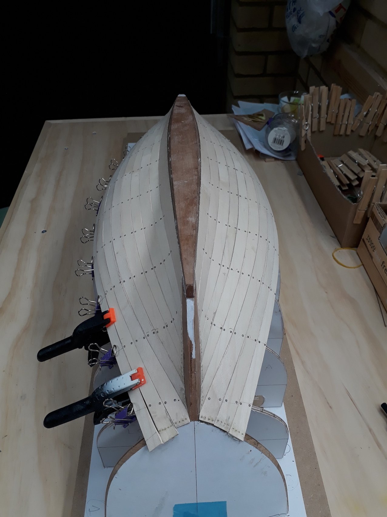
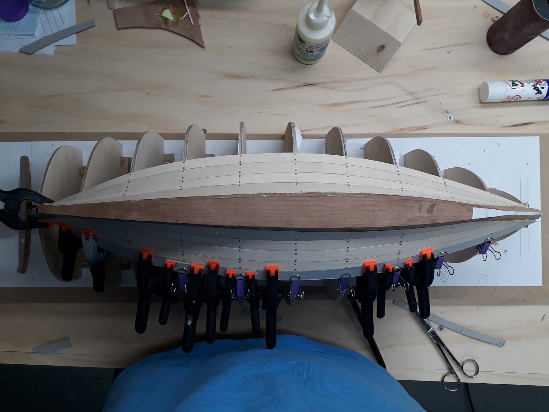
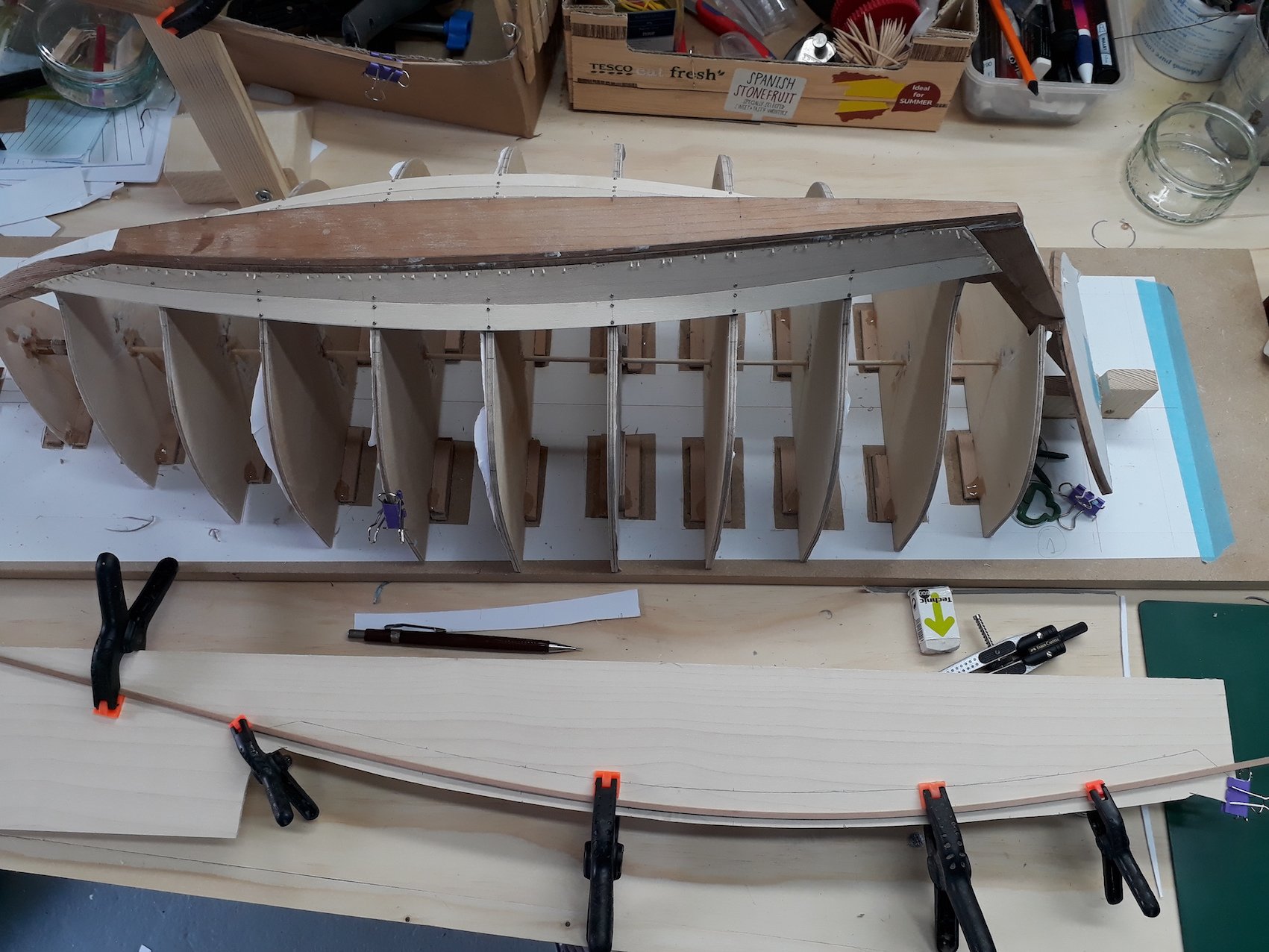
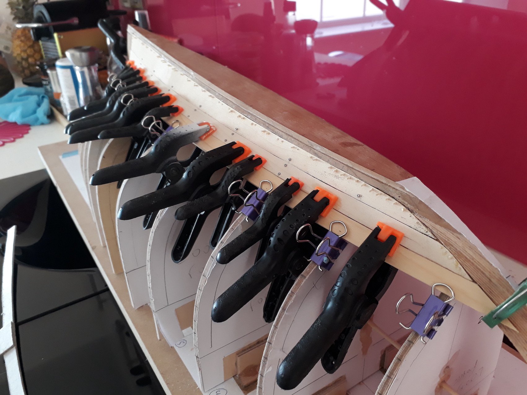
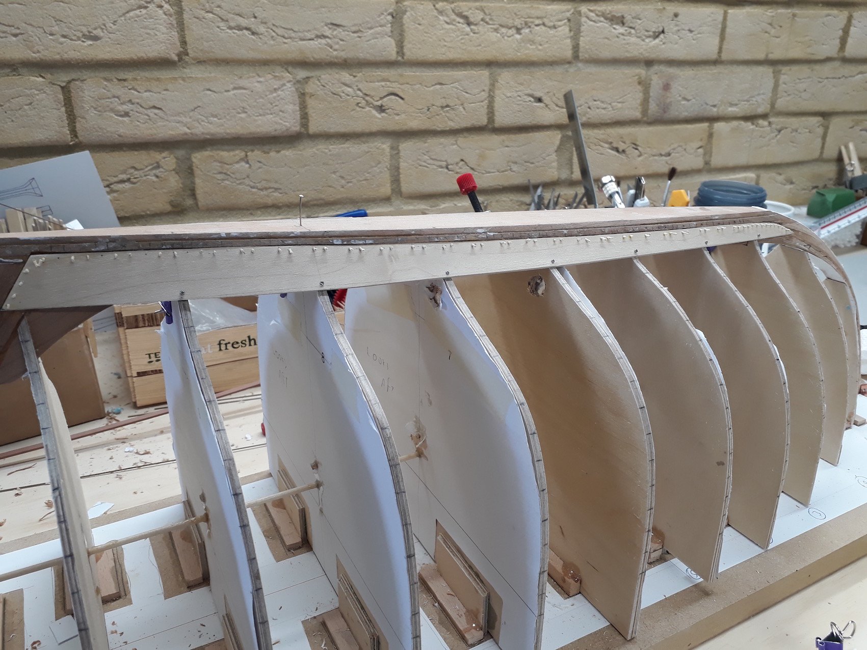
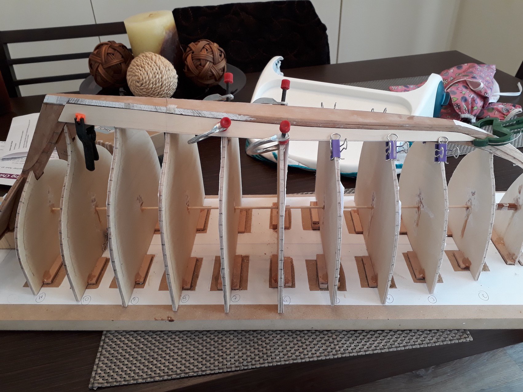
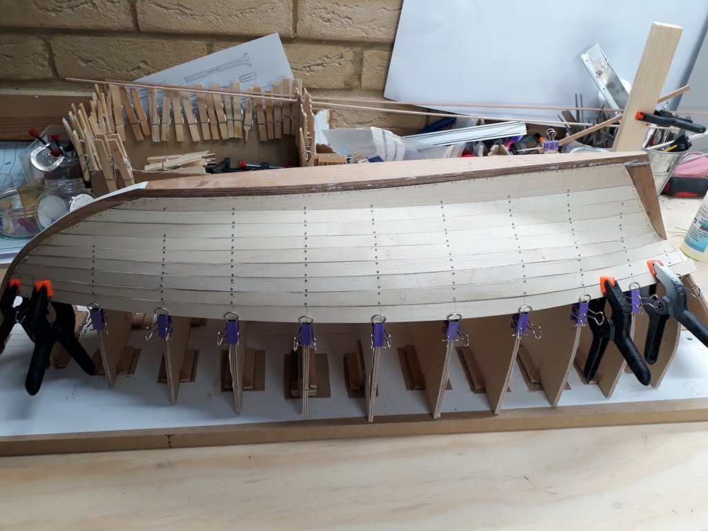
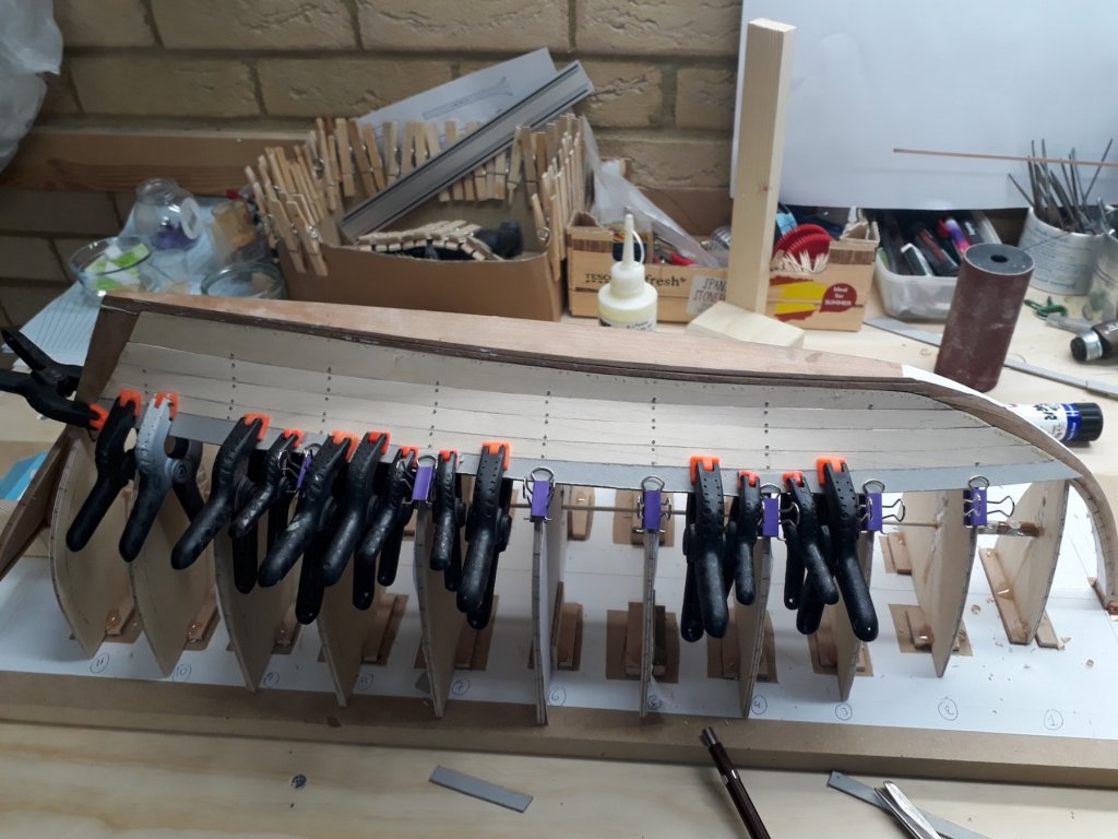
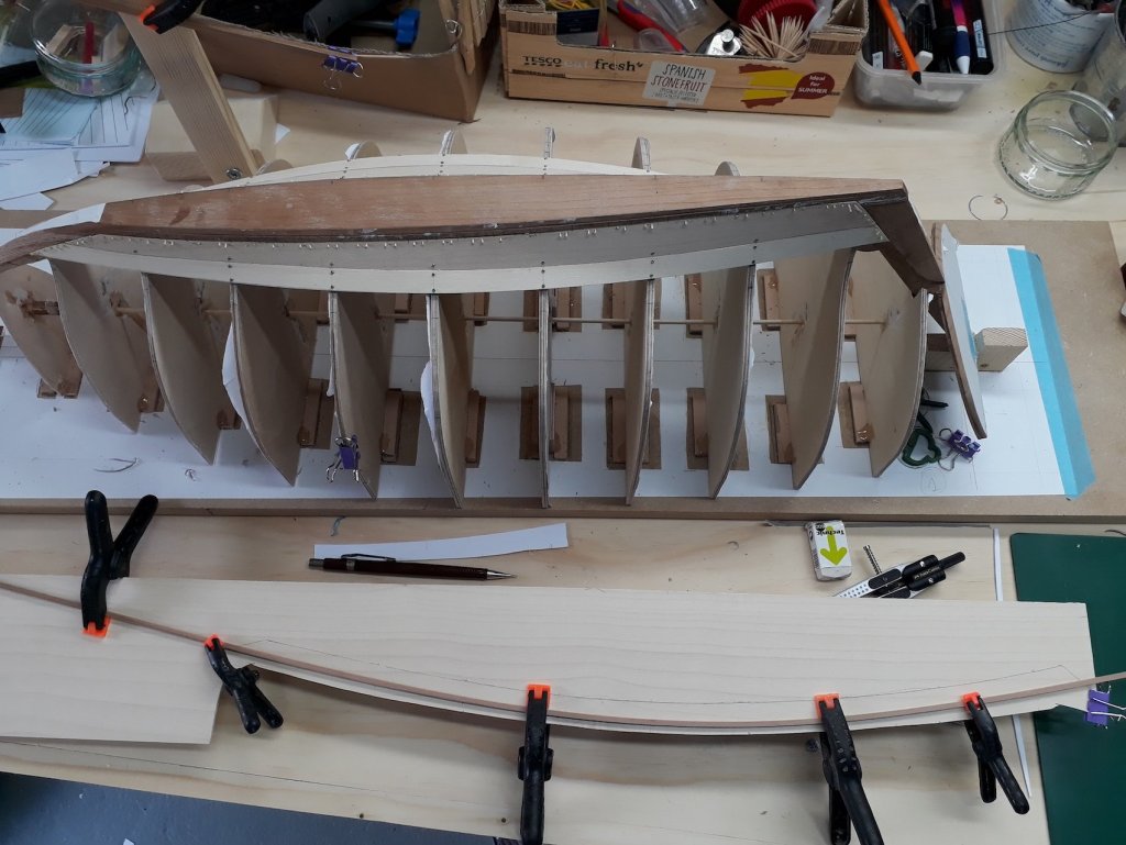
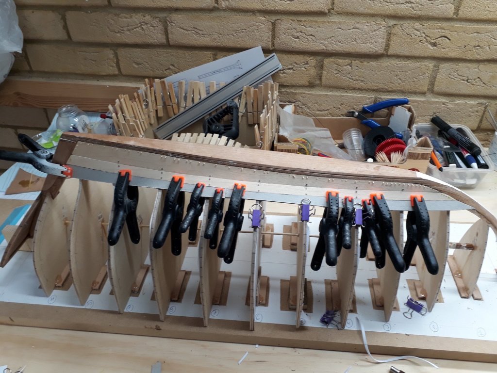
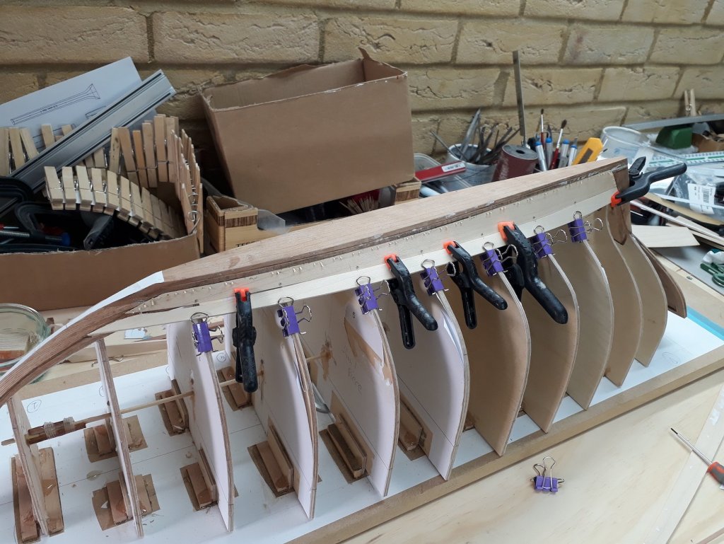
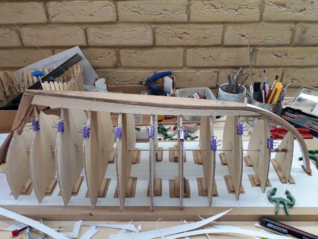
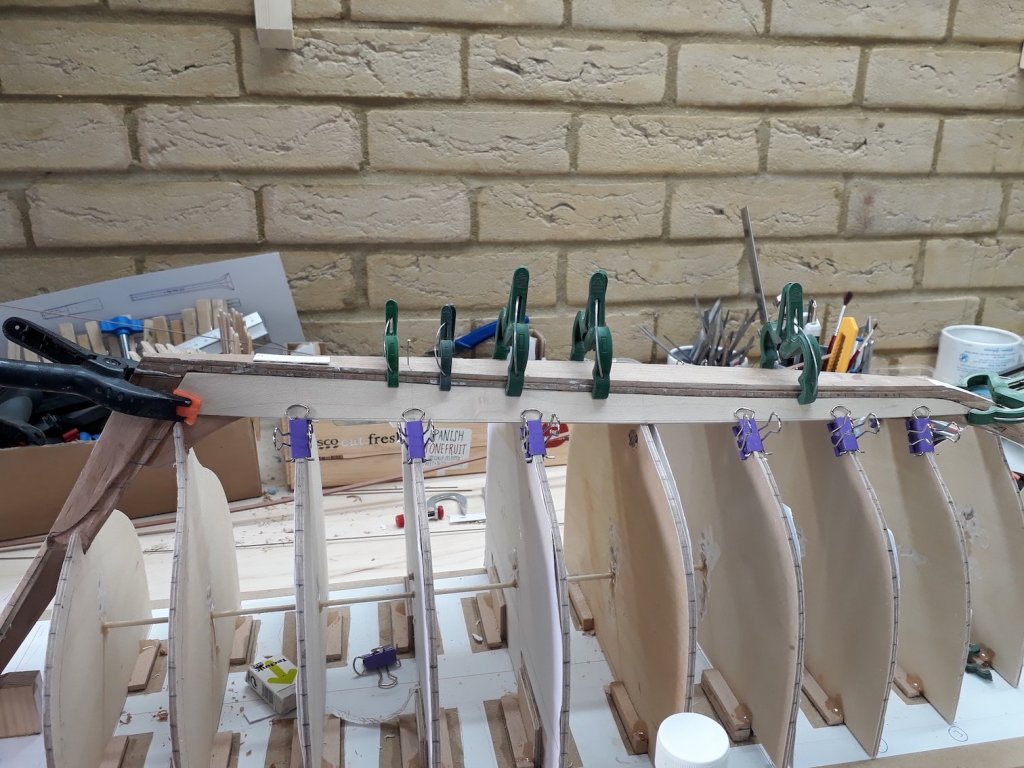
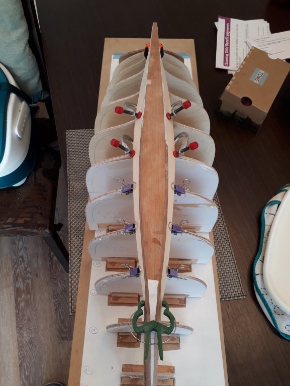
Planking slowly continues but now much less spilling is needed and the twist is much less. The planks are becoming though very long. These are two A4 mats, this plank (still unfinished) 2/3 of the way towards the sheer is around 70 cm long! The hull is slowly starting to show its curves and although very rough yet, it already has the inherent elegance of all wooden boats. As I gain experience the gaps between the planks are getting smaller. The starboard plank is temporarily held in place with clips. A problem which I need to figure out is how to get the boat off the MDF base so I can turn it around and install the ribs. The frames are 3 mm made of two sheets plywood 1.5 mm laminated together with epoxy. They are super strong. These are epoxied to wood strips which in turn are glued to the MDF with PVA glue. The whole thing is very solid. After I install the sheer plank, there will be very little space to put any tools in there. Maybe I should soak the whole MDF plank in water overnight up to the level of the joint with the frames, this should dissolve the PVA glue. Or mess everything up!


-
Thanks Jon! Oh yes, it is coming along and for first attempt it is probably ok. There are significant issues but all part of the learning curve. I guess that now with babies and all I am rushing things and often I am not happy with the outcome since I know I probably could have done it better. But I must compromise: It has taken me one and a half years to get this far! This is going to be a long journey. But sometimes, as I see the hull emerge plank by plank, I feel like a child again!
-
Thanks Patrick! (Of course I did choose the best angles to take photos) Turning it RC is a temptation! But I would need to invest time to learn about RC as I know nothing about it and money and both are in very short supply right now. Maybe the next (bigger) one!
-
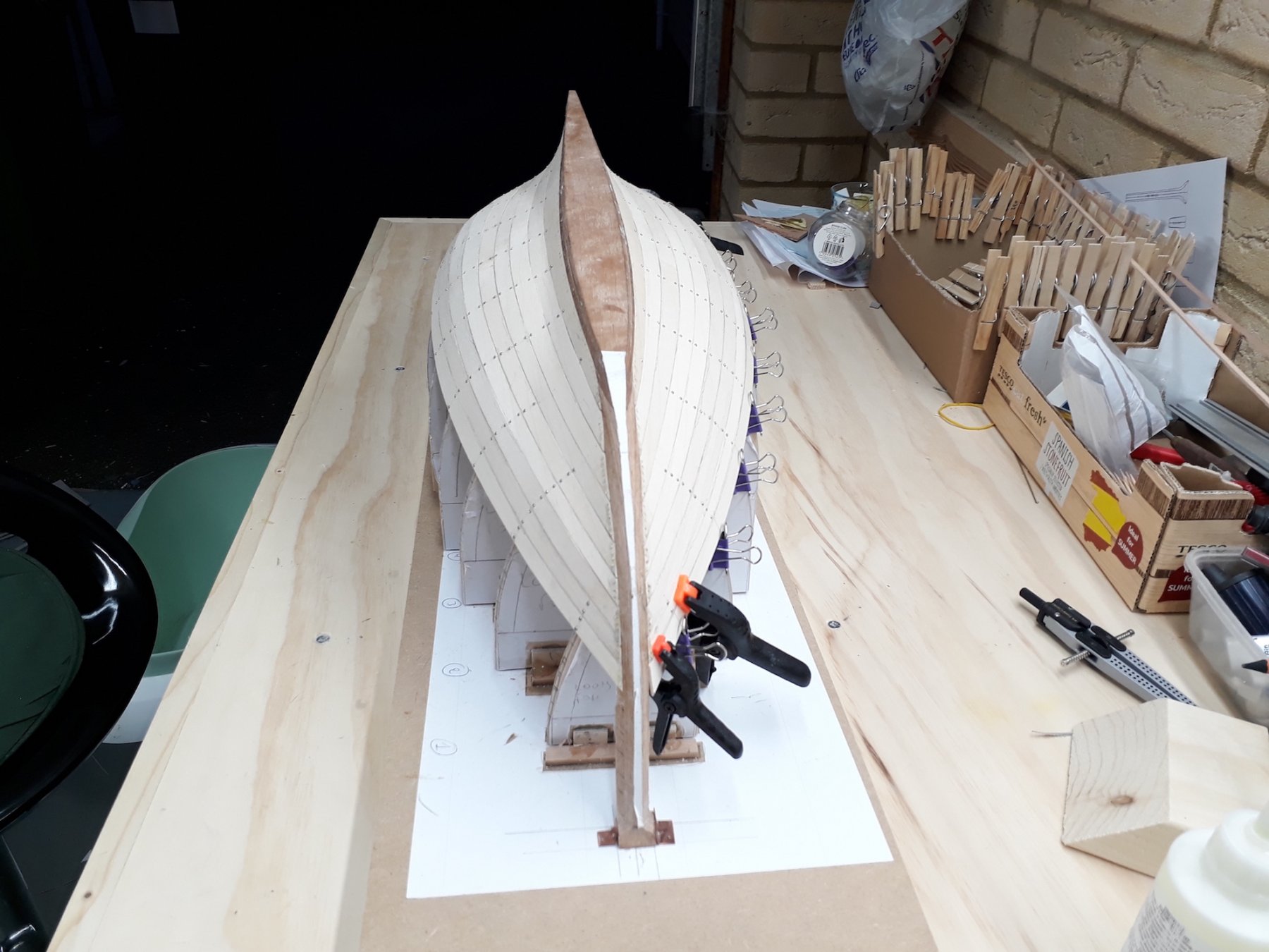
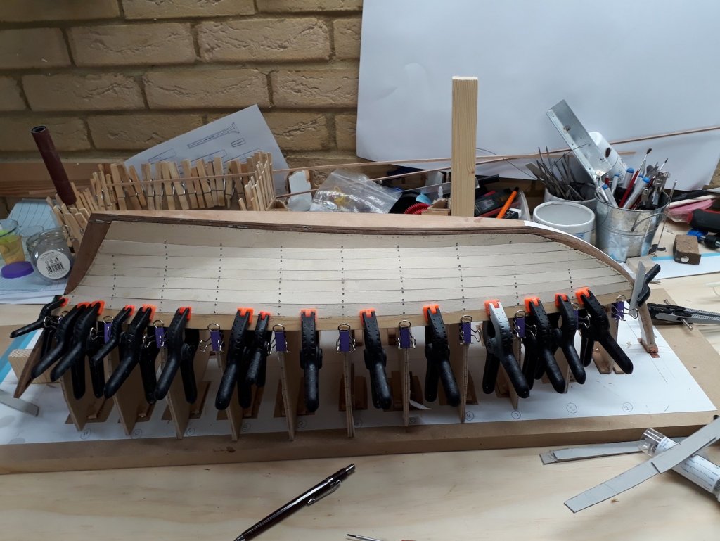
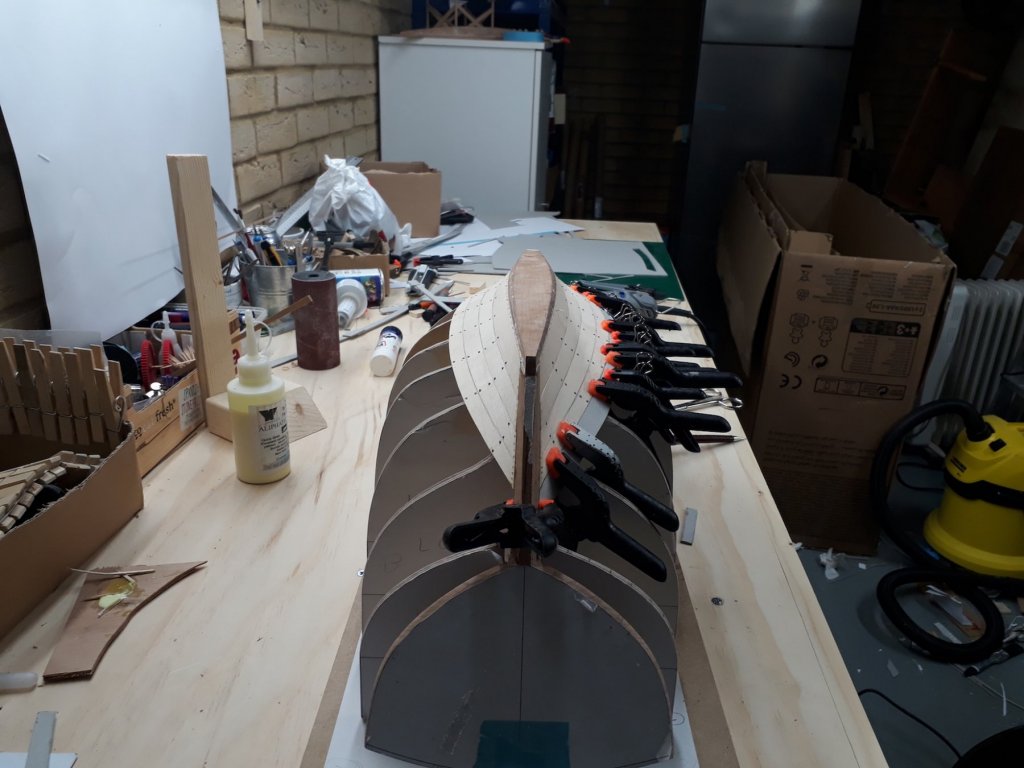
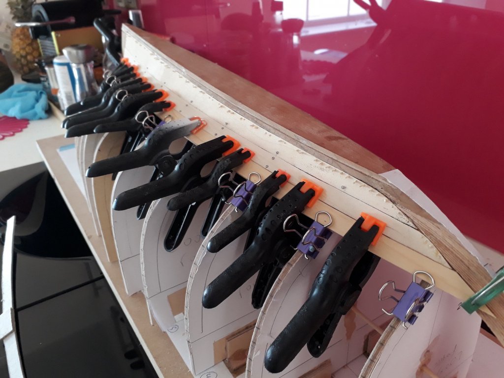
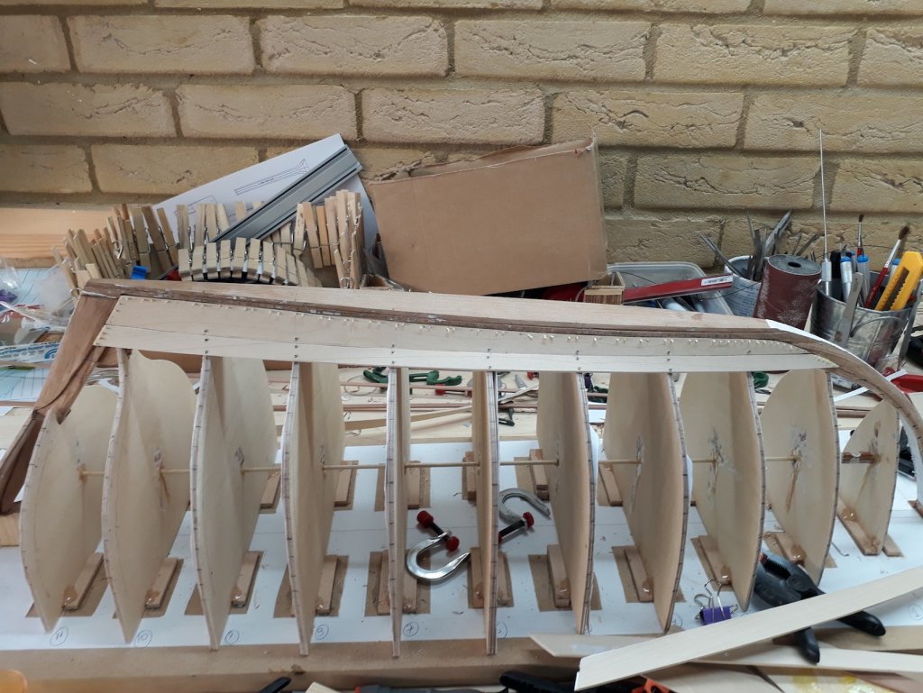
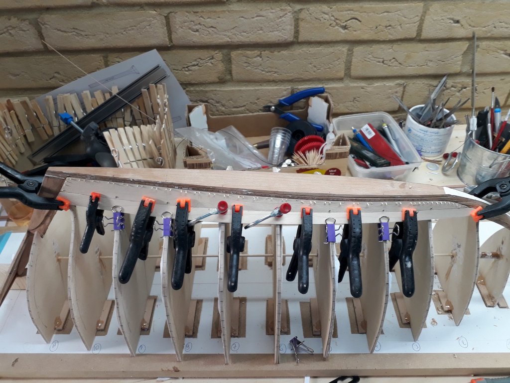
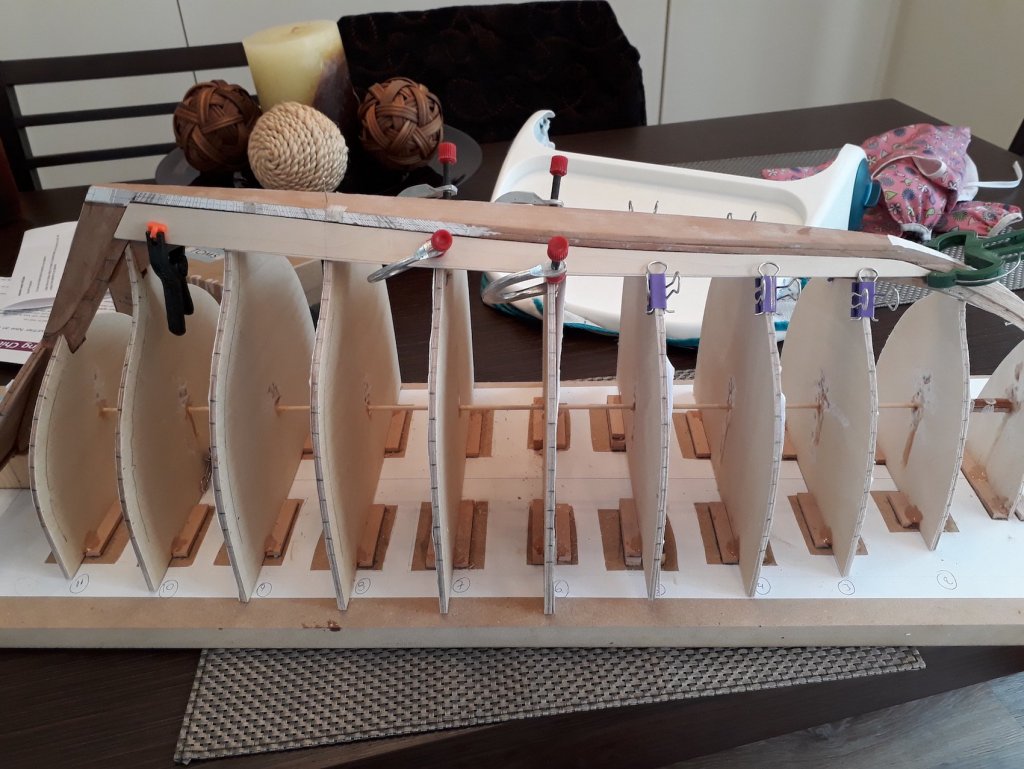
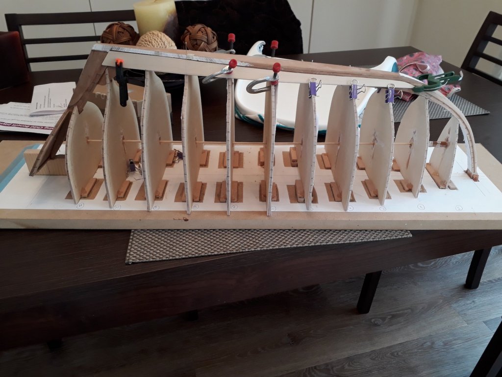
Planking continues! Thanks Druxey, indeed this boat was intended to be a learning tool as well as a model. I have certainly learned a lot so far! This scale I believe is the most difficult to work at. The planks now are 60 to 70 cm long and all imperfections appear huge! Also, wood needs to be chosen carefully to avoid twisted grain. I have standardised a way of producing planks and I am learning from my mistakes. Still, it is a lengthy and difficult process to produce each plank although both the twist and the spilling are now getting easier. Some photos of the progress so far. When the steamed ribs are in place the planks will hopefully align. Then the screws will go, the temp frames will be removed and the screw holes plugged with tree nails. Then filler will go in the gaps between the planks from both sides and the hull will be sanded. I hope this will produce a reasonably smooth hull.


-
I was catching up with your log Patrick and I started thinking "where is the galley" and voila! last post answered this one I loved the picture with all 5 decks in a row. I think the 4th one up is for me, having cocktails as the sun sets. Lovely work, very nice!
-
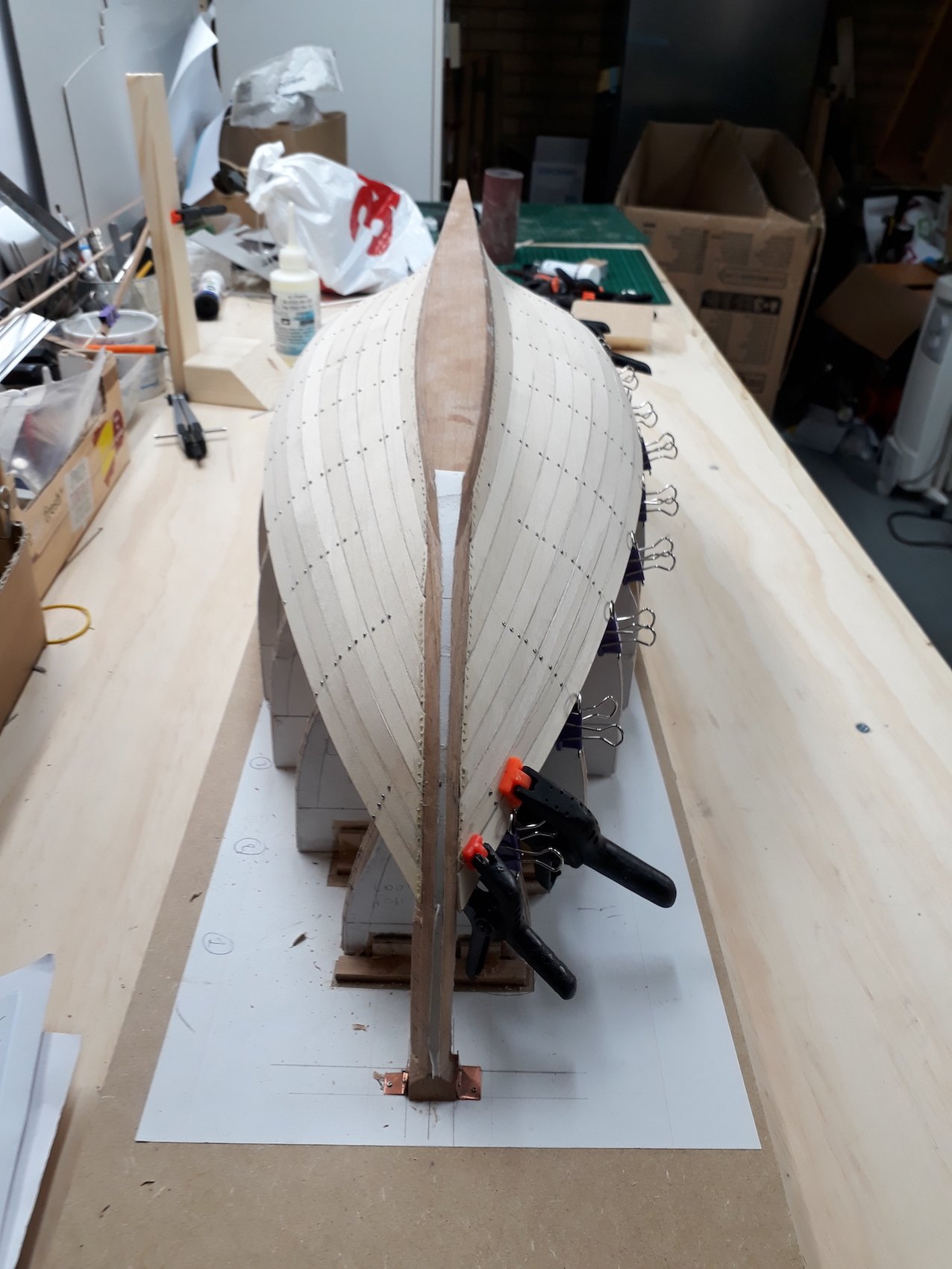
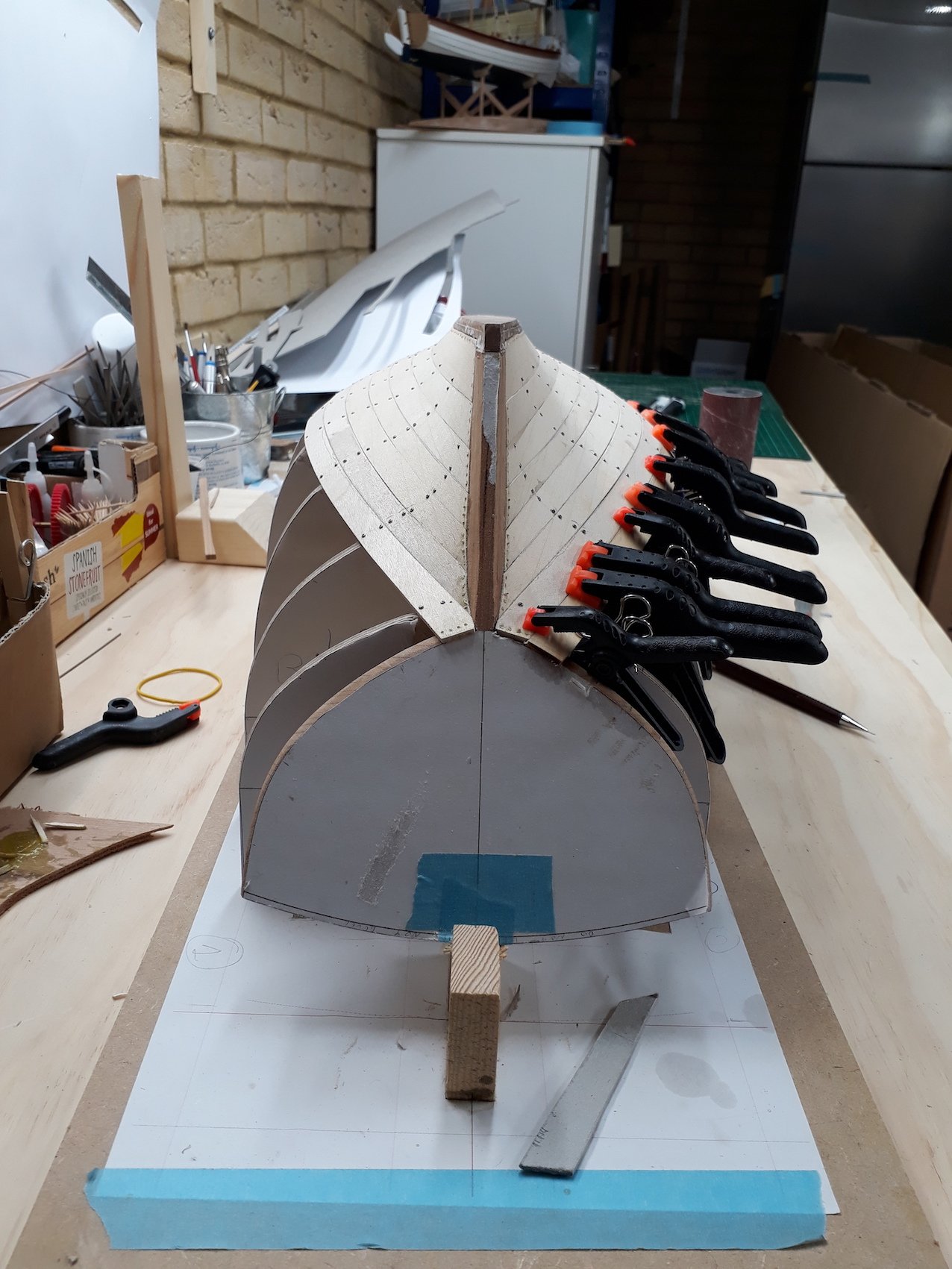
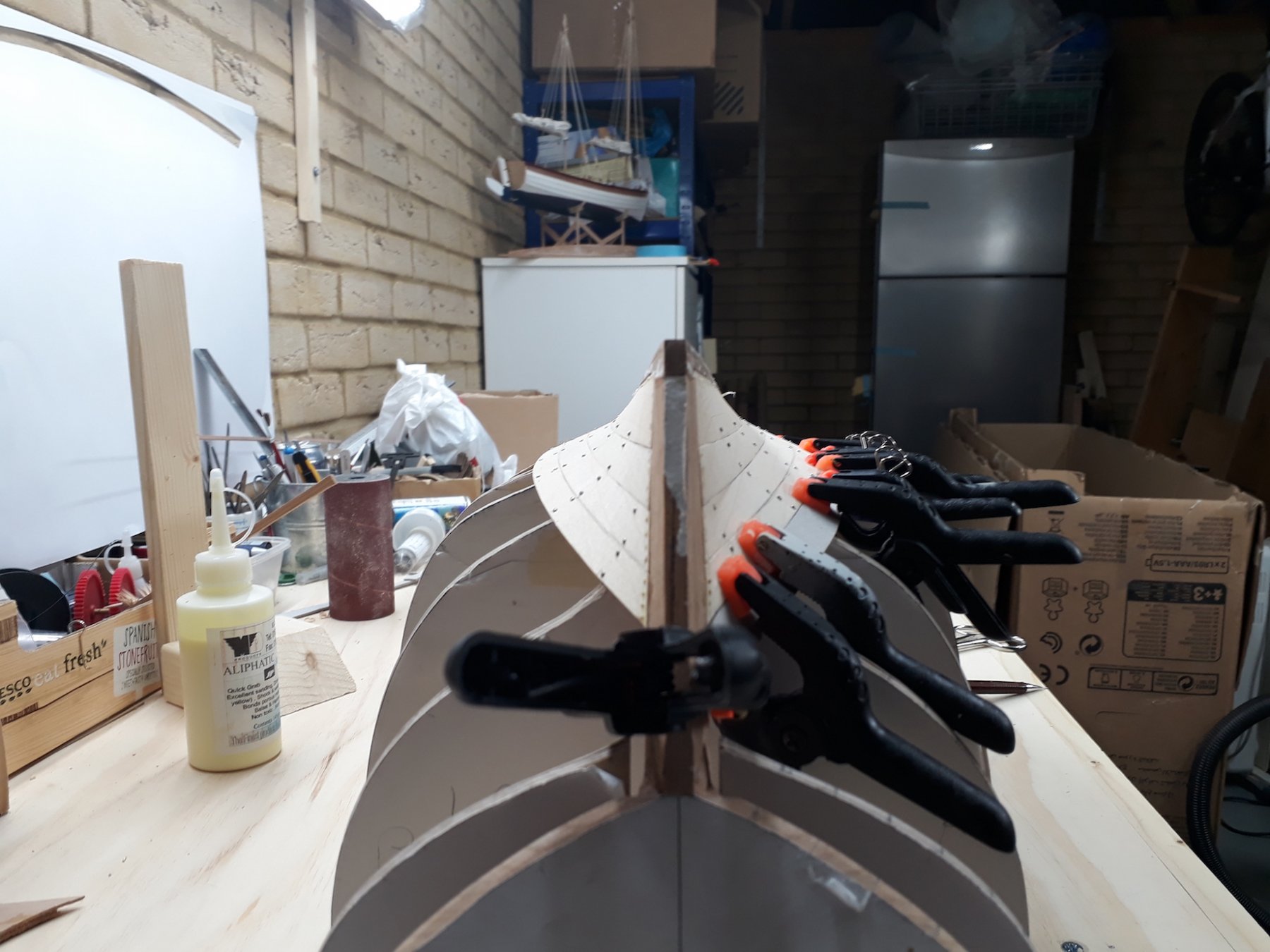
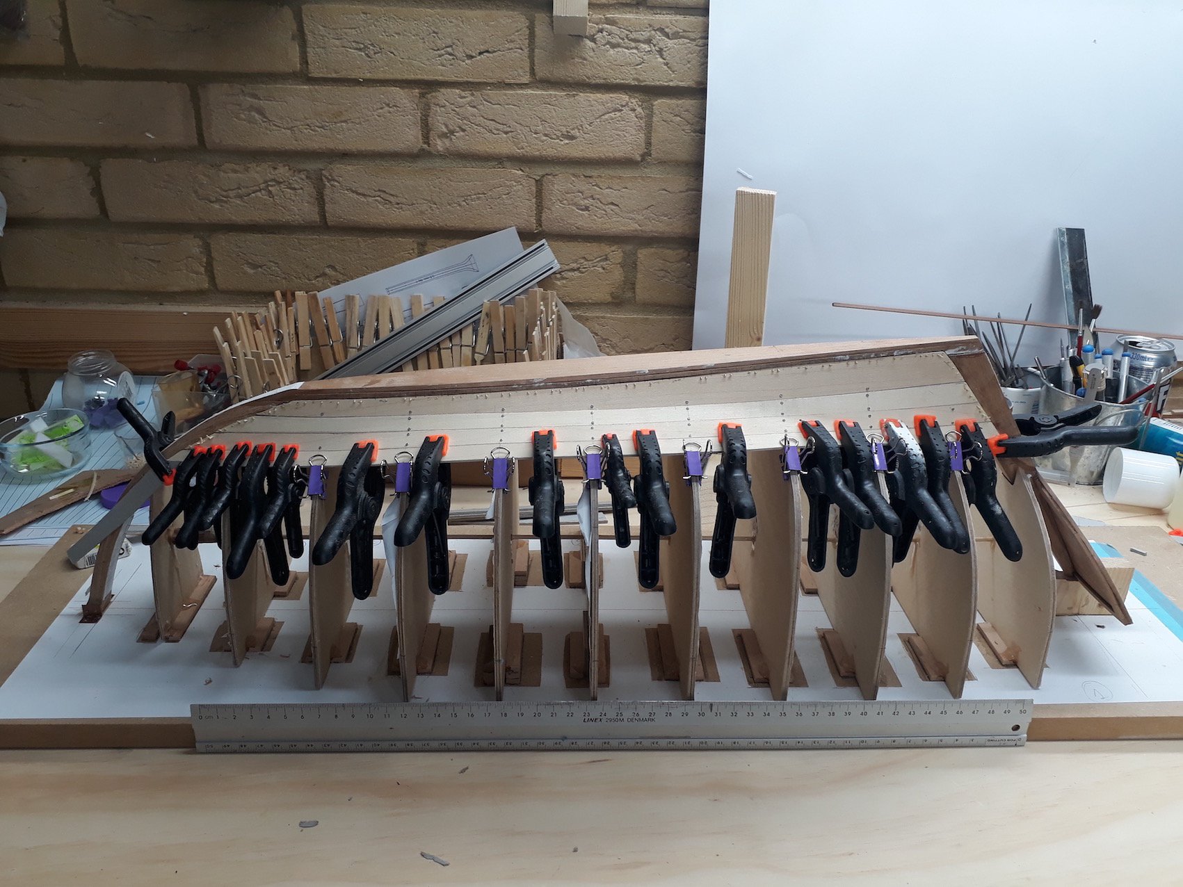
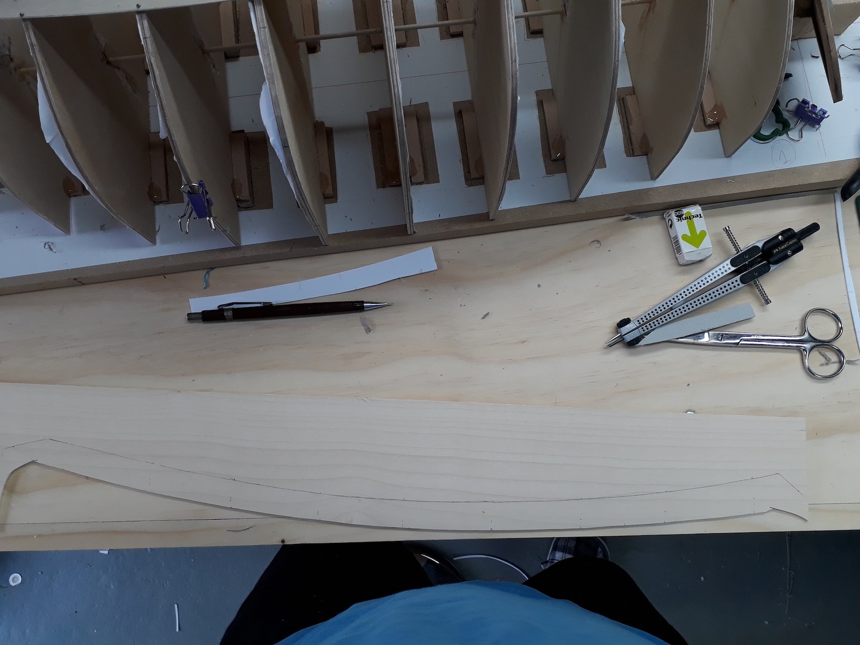
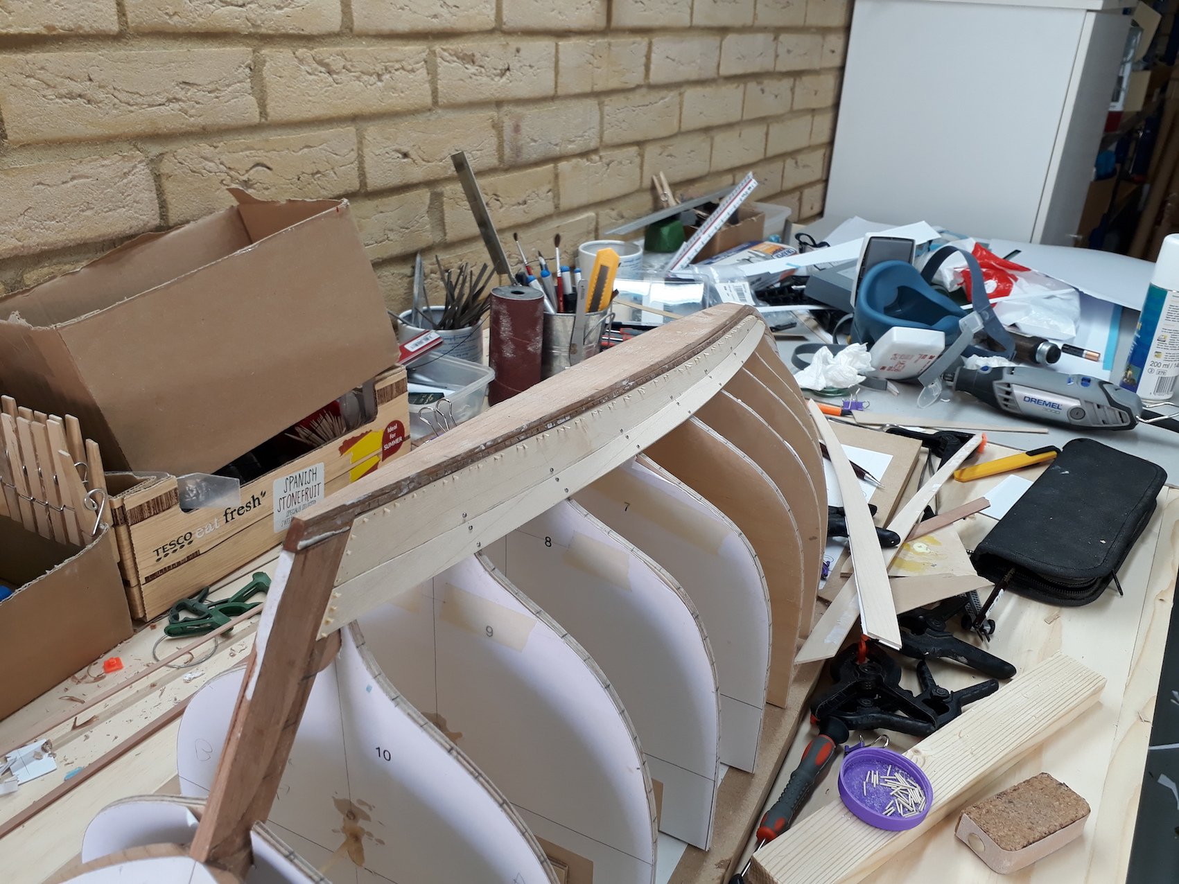
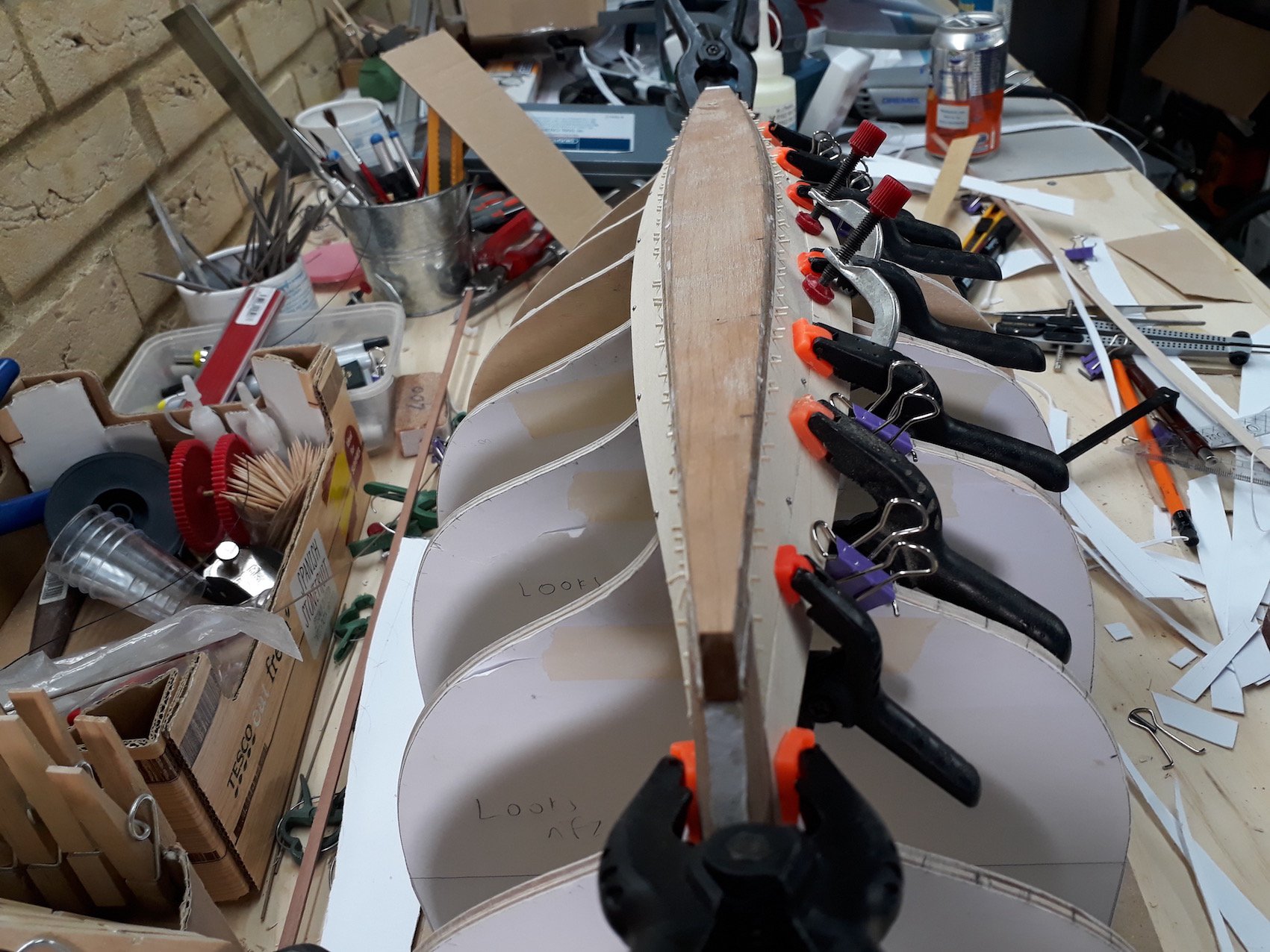
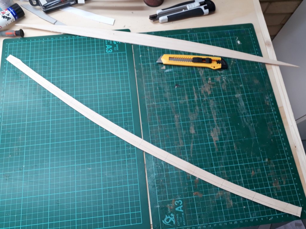
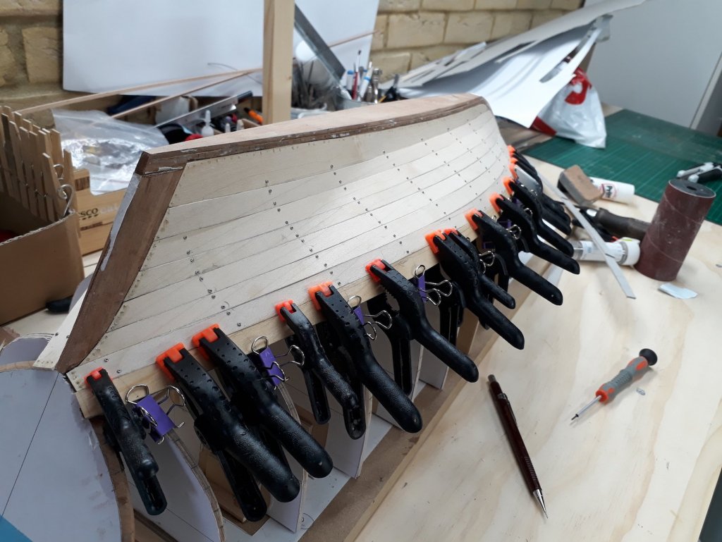
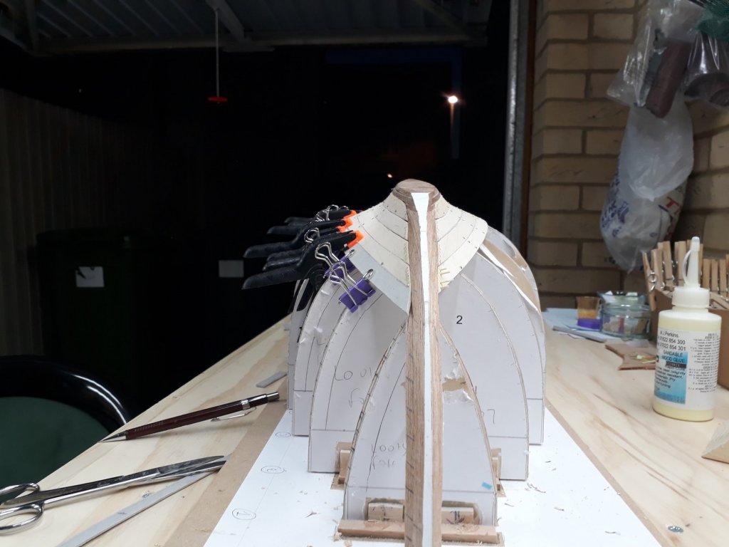
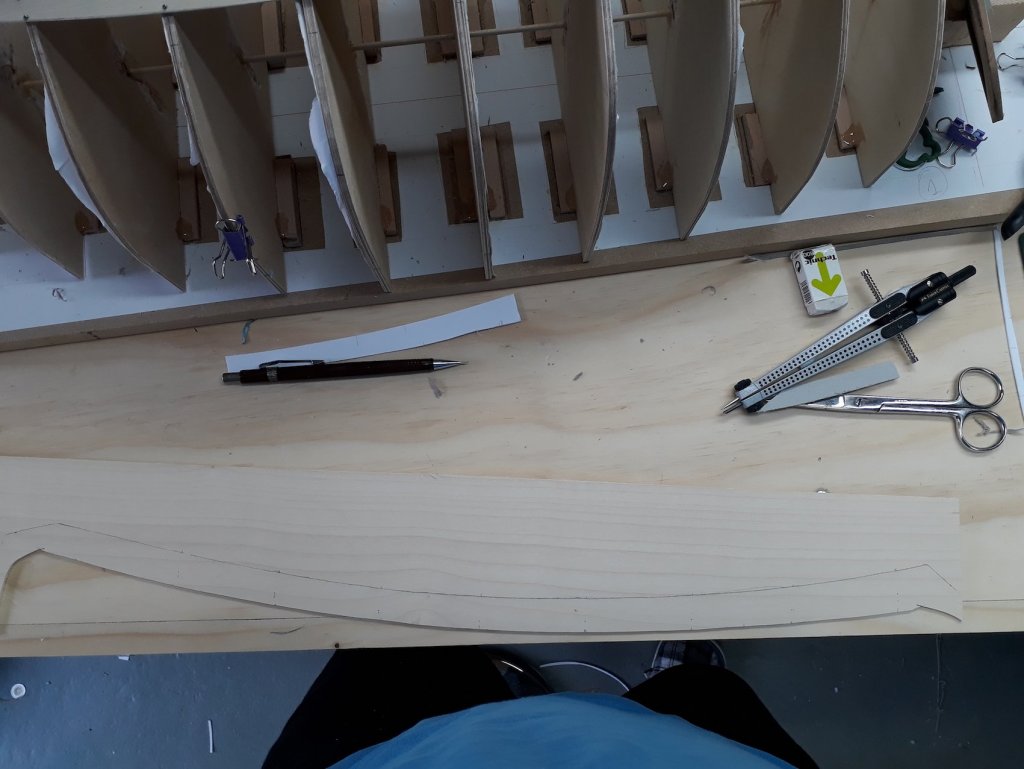
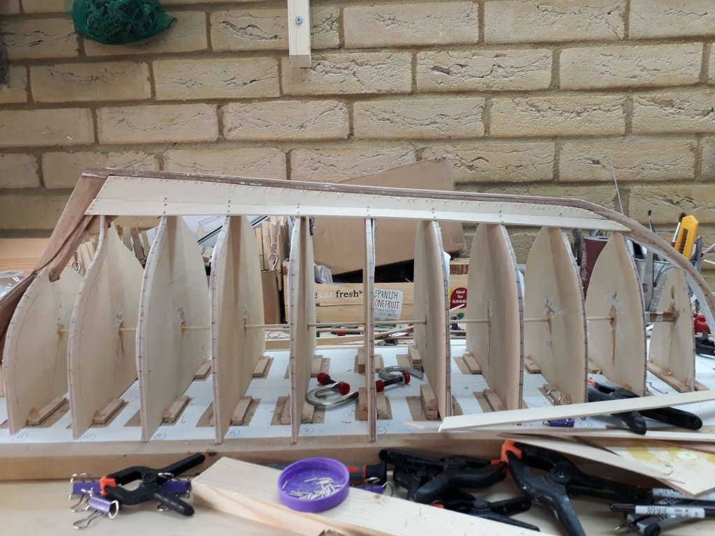
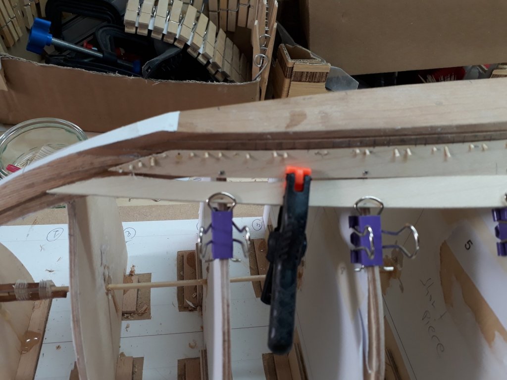
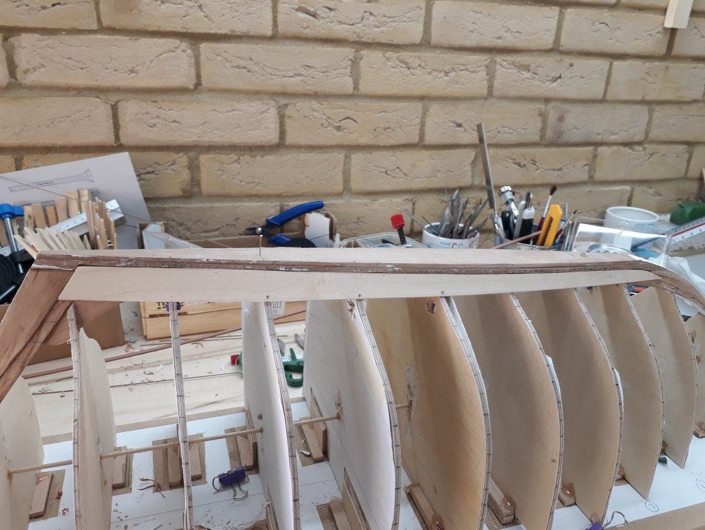
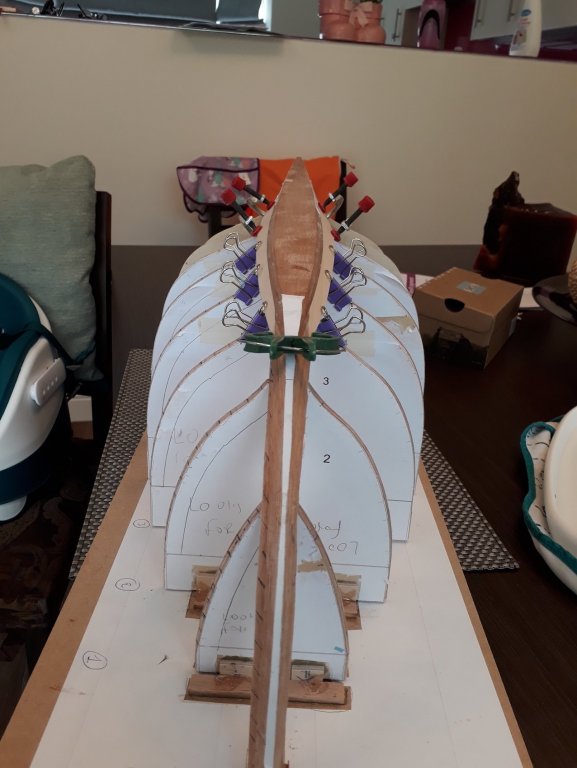
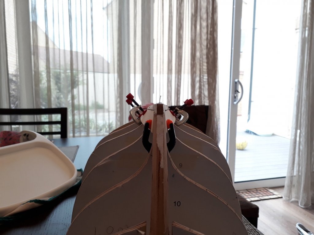
Actually there are 3 progressively more difficult planks left each side before things get easier. The boat is so large that each 100 cm maple sheet gives about 3 planks only! The ruler in the next photo is 50 cm long. As the twist gets worse, it is more difficult to define the shape as even the cardboard resists going into place. It took a few tries to get the template right. It had to be done in 4 segments which are glued together, now waiting for the glue to set. I have a suspicion though that my planking is actually wrong. This is due to the garboard plank that i feel does not have the right shape. It should go a bit further up in the stern and bow and be thinner in the middle. This way, the rest of the planks would need less spilling. Also, I now realise that the rebate line needs to be cut with extreme care and also that the planks at this scale need to be prepared very carefully as well. I was very sloppy and now all defects appear huge! Lessons learned (the hard way). Anyway, despite all these, it is starting to look like a boat! View from the bow View from the stern


-
Thanks John, indeed I think I ve cracked this. The twist is causing lots of problems when dry fitting the plank during the actual making. 2 more to go each side though and then it will get much easier as I ll be at the transom.
-
Indeed, Allan, Druxey is right. The boat I am building turned out to be really complex! I ve cracked the planking, still a handful though with each plank 60+ cm long and 2 mm thick...
-
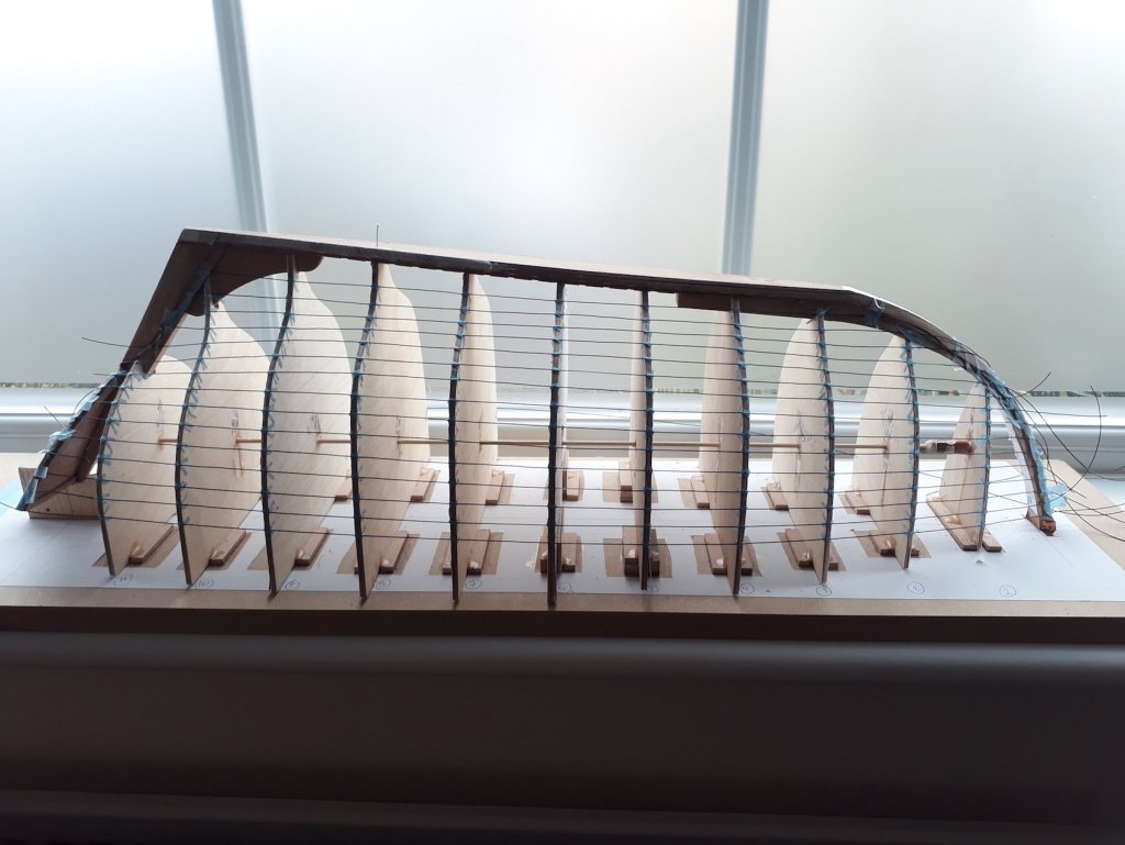
I think I should post my recent experience as it might help some first timers in planking like myself. I realised that I probably got my GB plank wrong. I have gone as far as installing the first 5 planks (GB plank upwards). You can see the shape of the GB in the photo above. The problem is, that as planking progresses, the spilling gets more aggressive up until the 7th plank (in my hull at least) and then it eases off. Now, my GB is already spilled so things get pretty bad with spilling as I progress. If I had taken the gb a bit higher in the stem (not much) and thinned the plank in the middle, given it a bit of a butterfly appearance, I would probably need much less spilling for the rest of the planks. This is why there is the advice of keeping the upper edge as straight as possible. I suspect my spilling will get a bit unrealistic and my wood wastage is huge. Lesson learned though!
-
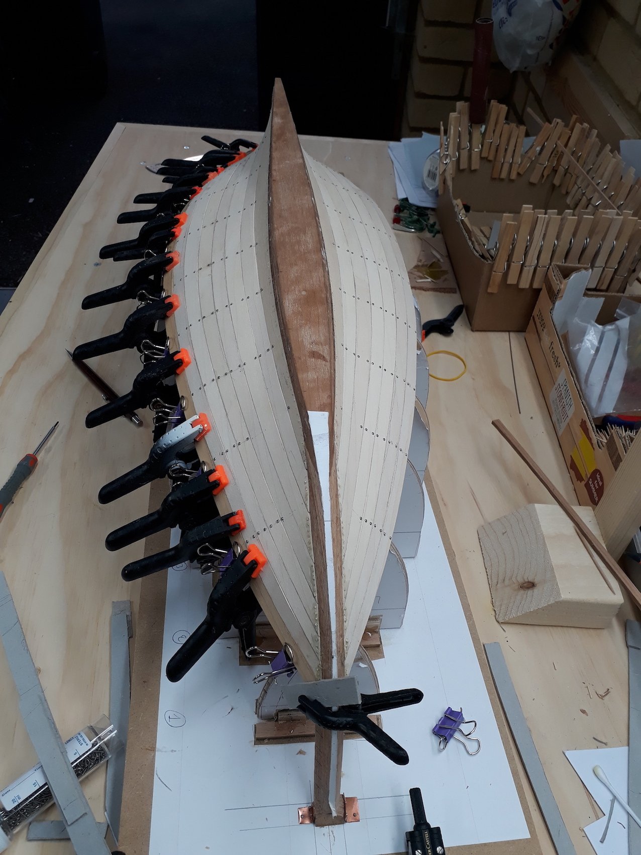
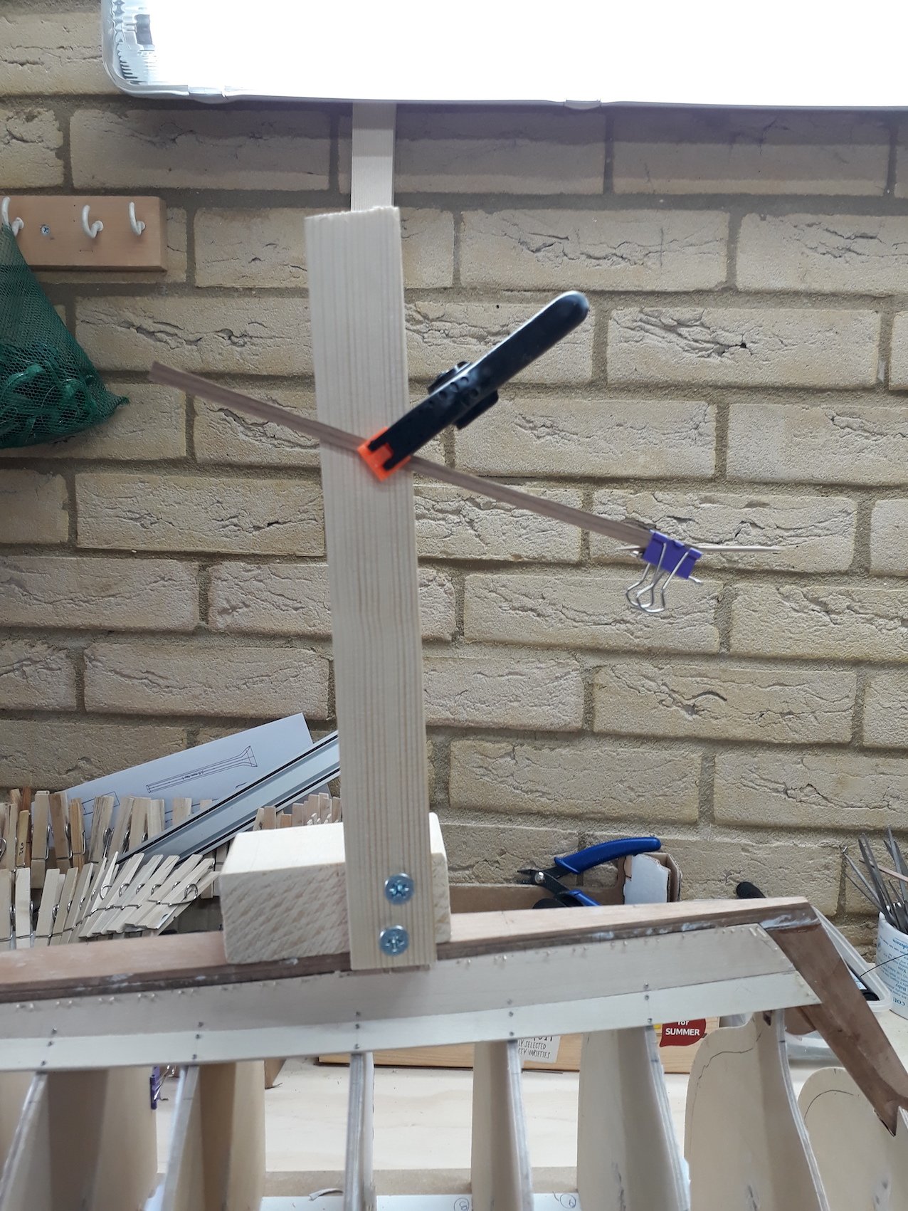
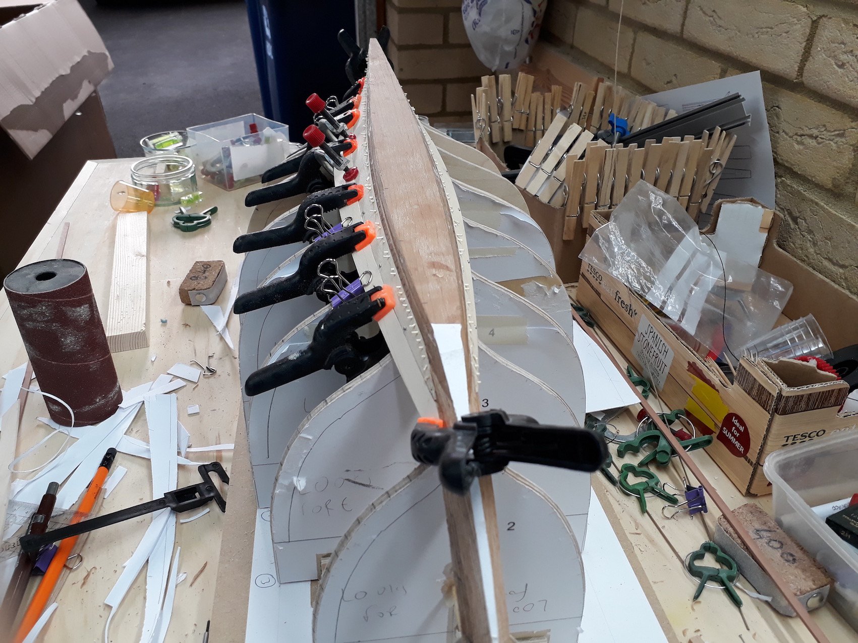
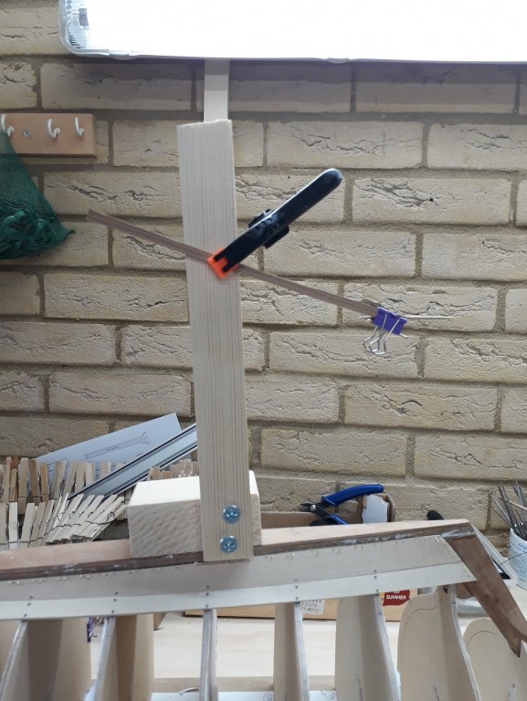
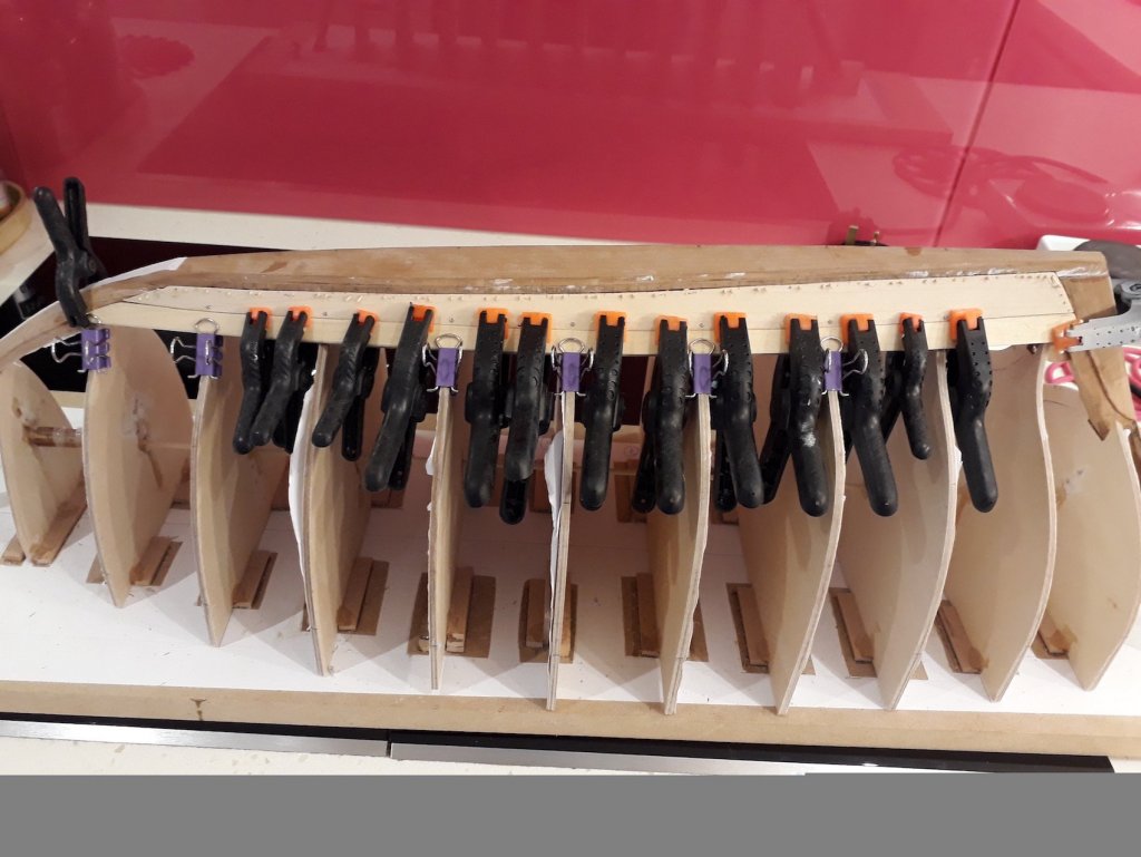
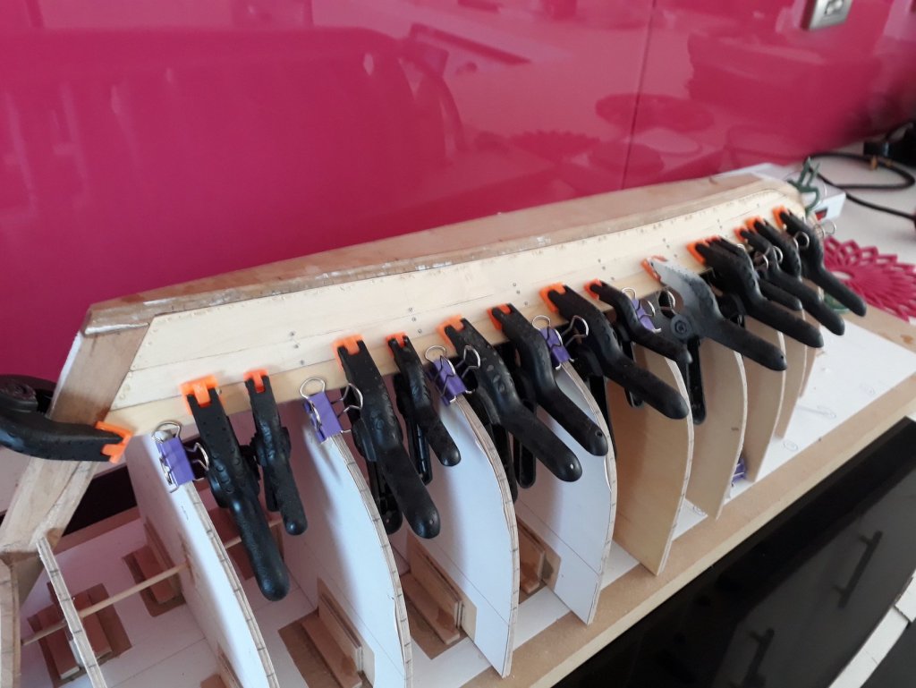
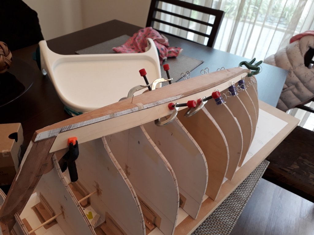
Thank you all for the likes and encouragement Patrick, I think this moto should be added to the forum logo at the upper left corner of the page! Druxey, that's a good word indeed! To be used when there is far more wood dust than elegance. I looked into buying a height gauge but they are too expensive. I needed it to transfer the height of the lower edge of the planks on the frames (corresponding to the width of the plank) from the marked side to the other. I made a Franken-gauge that worked pretty well. I then made the pattern for the third plank on the starboard side and cut the plank. I used the compass to outline the shape of the upper edge. Then transferred the shape onto the maple sheet, having marked the position of the frames. I then measured and transferred the width of the plank at the frames to the sheet. Then, I used a batten to draw the lower edge of the plank so that it would be a fair curve. I installed the plank and sanded the high spots so that the plank would sit as close to the previous plank as possible. Success with the first try again! The spilling is quite significant but entirely possible in real life. It would mean huge wastage though! 3 more planks each side to go, with progressively worse twist at the stern and then I ll be at the transom. Looking at the garboard plank, I think that if the shape was different, going a bit higher at the bow and stern and left narrow at the middle, the rest of the planks would need much less spilling. I guess those practicums were right!
-
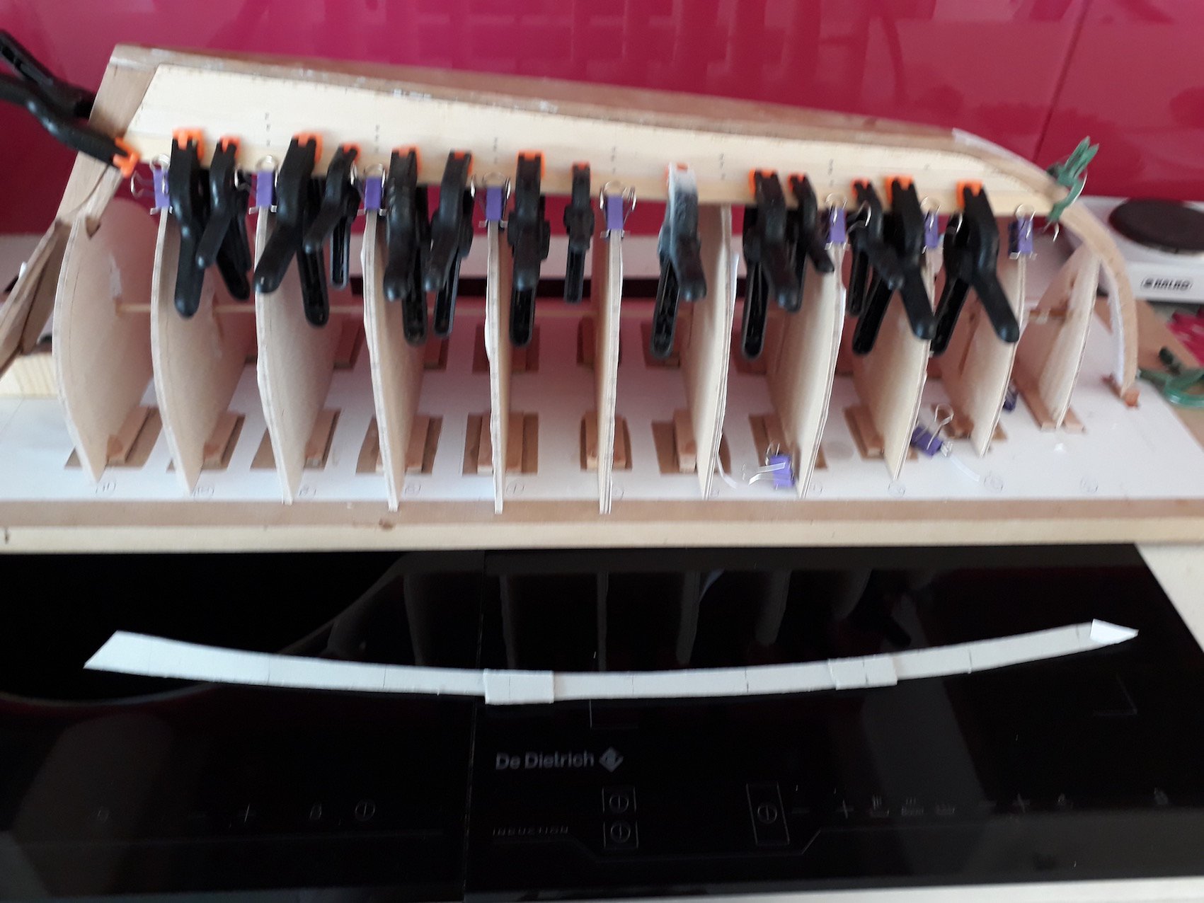
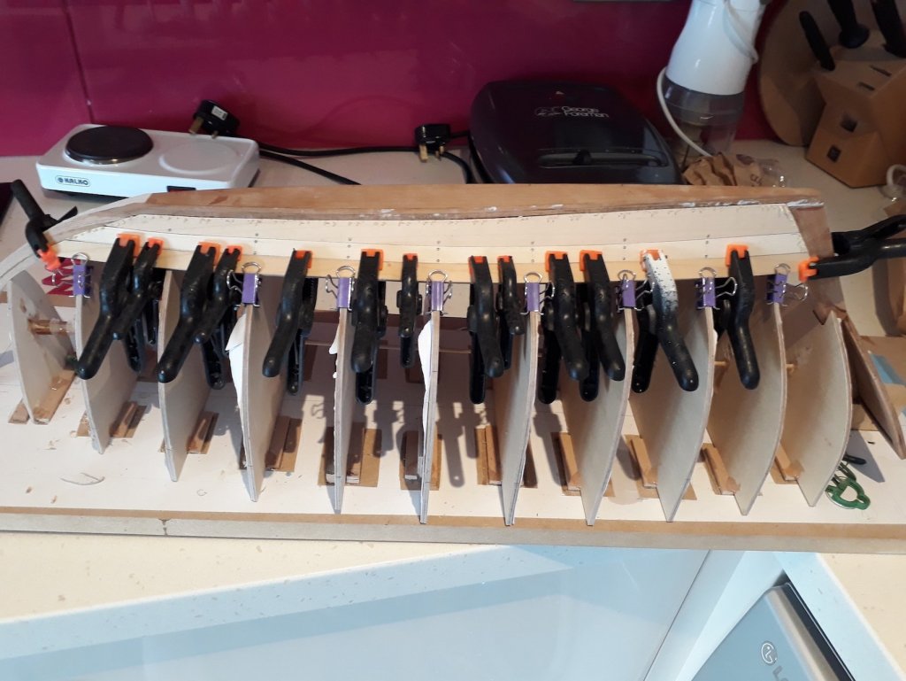
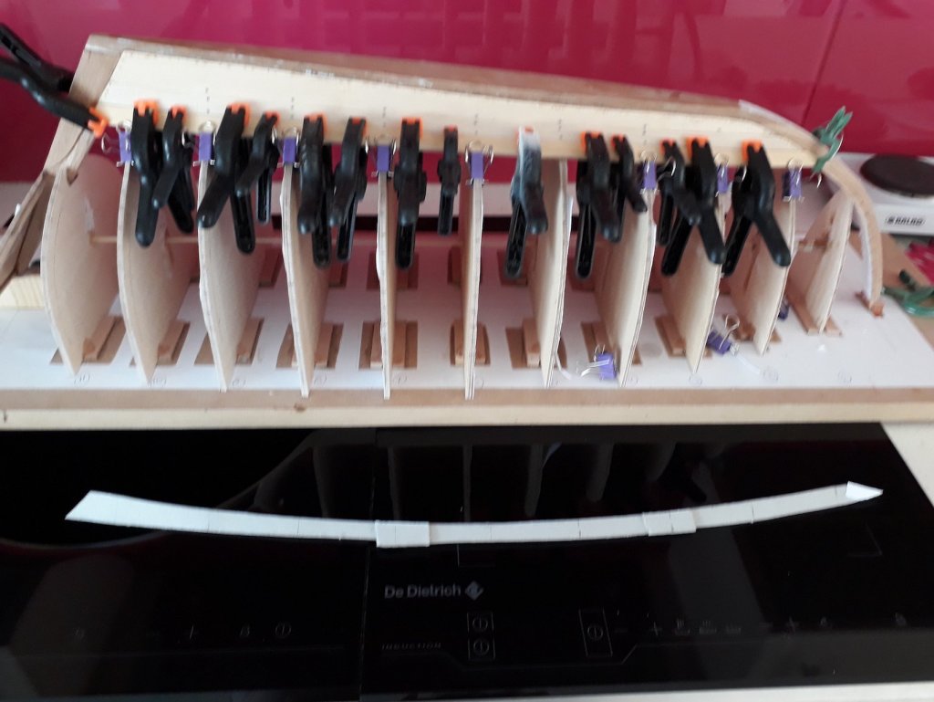
Thank you all, I really need the support in my fight against these stubborn planks. I finally got the second plank right. It took countless tries and a forest of wasted wood. Still, I finally might have standardised a process. Instead of making a cardboard template for the whole of the plank, it works better if divided in sections which then are glued together while on the boat so the plank is formed. I got the third plank right on the first attempt. Just using hot tab water is enough to make the wood very pliable. As the planking is progressing, it gets more difficult as the twist at the stern becomes more pronounced. Only when I reach the transom will it get easier. I realise I do one plank a week, so at this pace I need another 30 weeks to finish the planking! So far I could not get the planks to fit snug to each other along all their length, this really would need skills I do not have. I pretend the gaps are left on purpose for the caulking... Best wishes to all Vaddoc
-
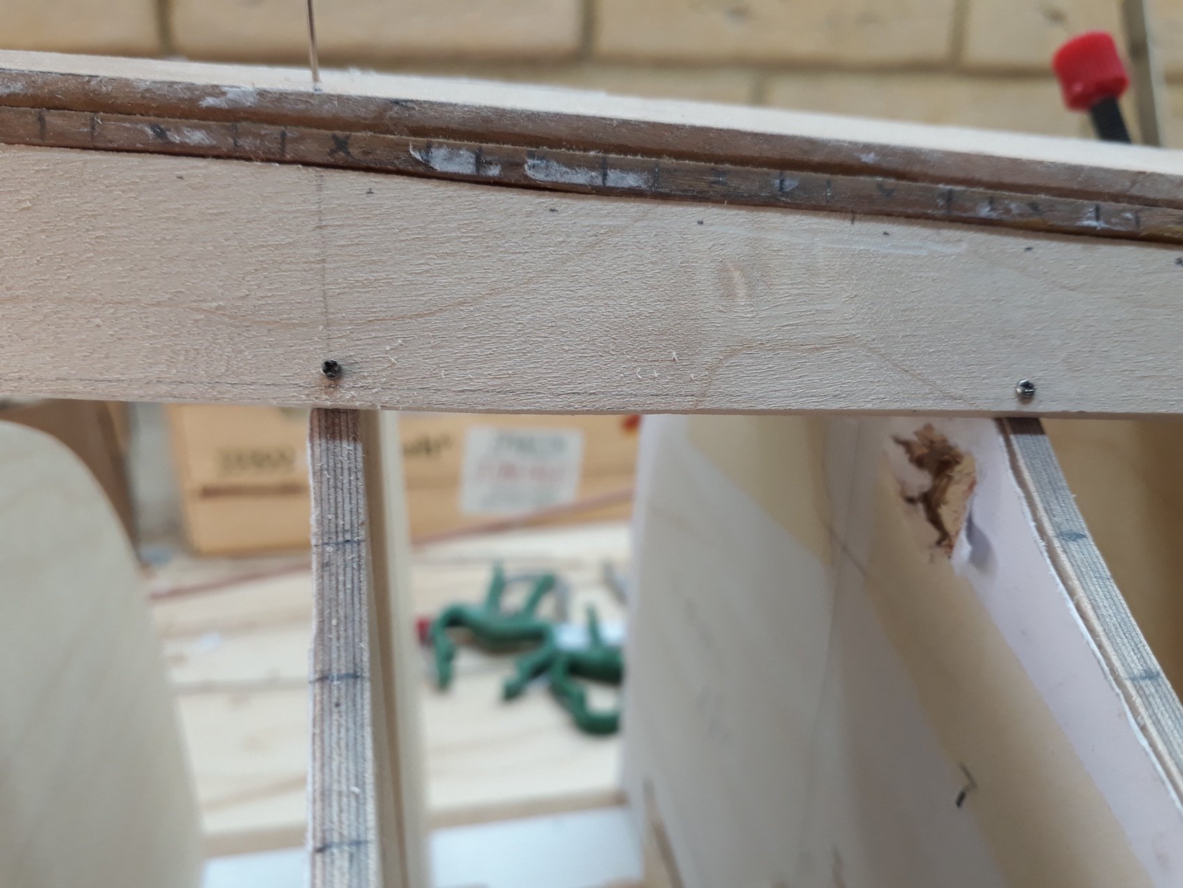
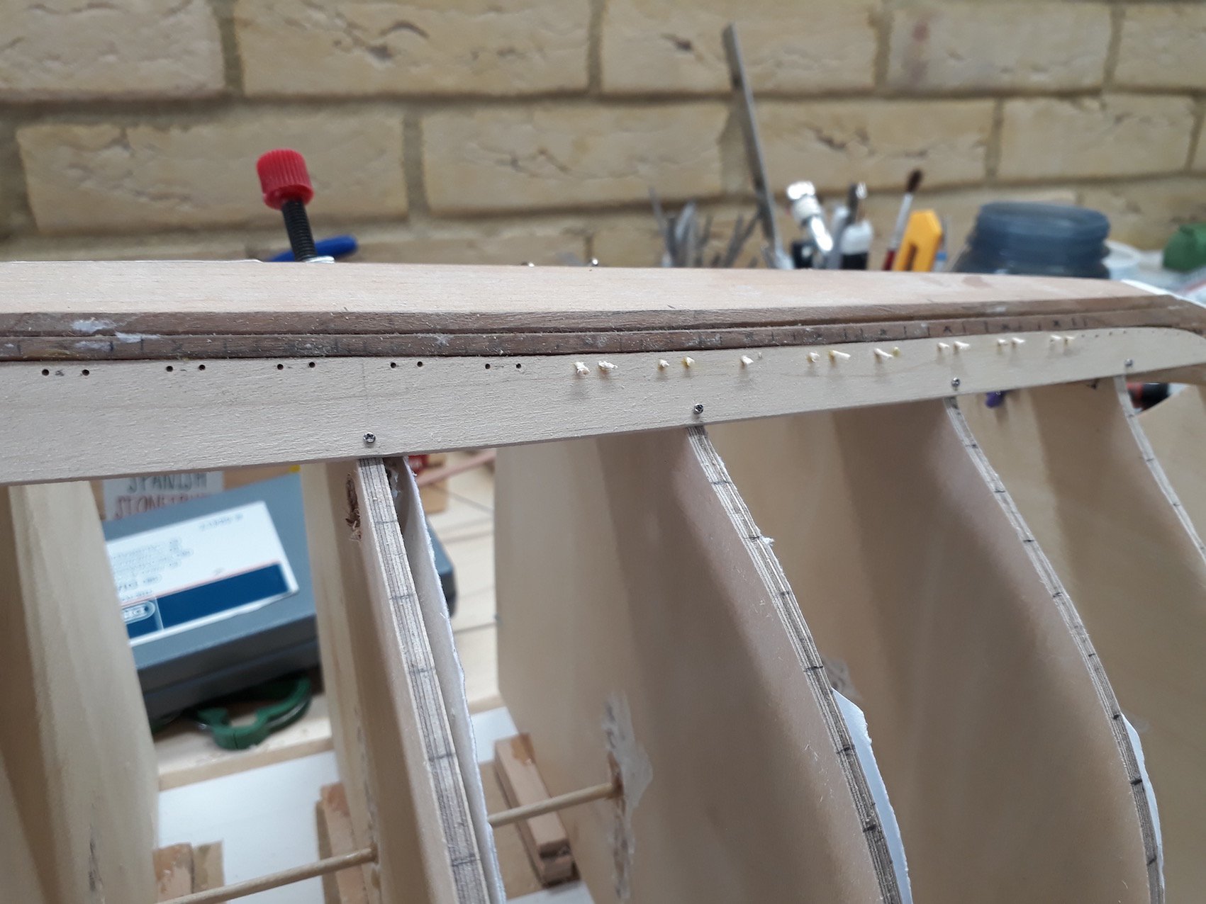
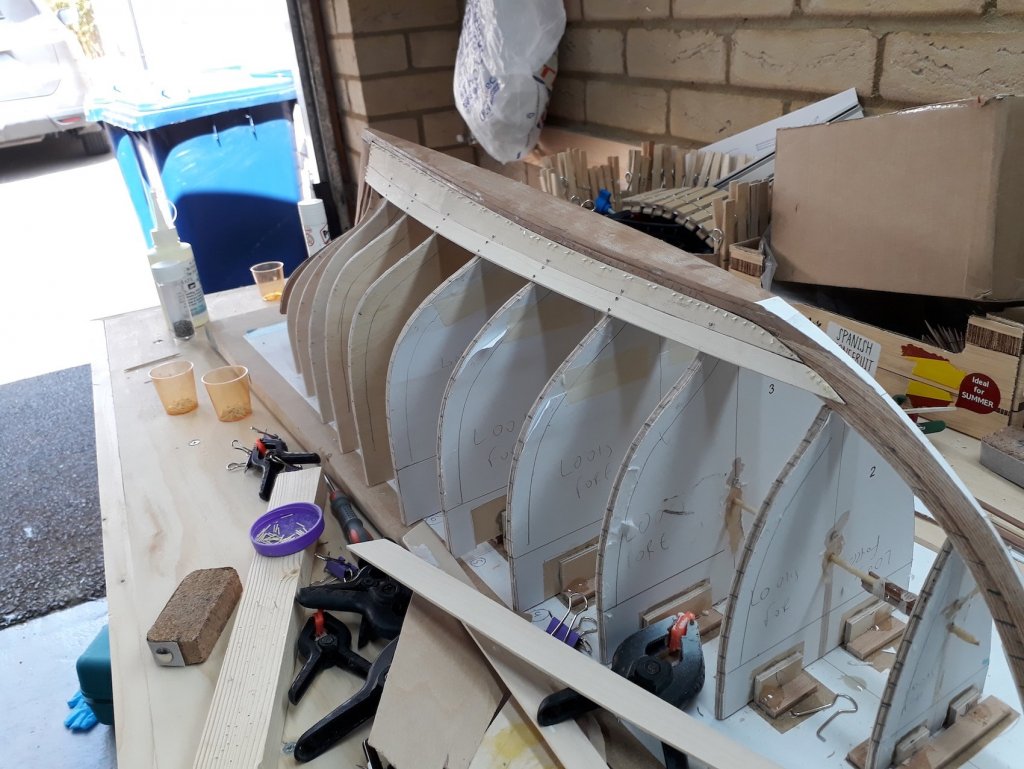
Dear all In the last 10 days I made more progress than I could hope for. Still, planking at this scale is a difficult job and each plank is as painful as having a tooth out! I fitted both garboard planks, I think they came out fine. The micro screws are easy to use and have huge holding strength. The tree nails are easy to insert. The gaps are left so that the steam bend frames can slide in the slots at the keel. Tree nails will be inserted later. I then started fitting the next plank on the port side. Lots of wasted timber, many strips of cardboard in funny shapes lying everywhere. I am quite happy with the outcome though! Next I started work on the other side. Close enough but not quite. Another wasted maple strip! I do have a problem though. When I designed the hull in 3D the lines seemed to show that the bow became hollow near the keel. I have cut the frames like this but the planks now seem to want to follow their natural curve there. I am thinking I will just put some sims in these areas at frame 2 and possibly frame 1 for the first 3 planks or so.


-
This is the GB plank in my boat after fitting Seems to climb up the stem about as much as yours Don (although the two boats are very different)
-
Thanks John! Yes, I used a rolled plastic bag and masking tape. It looks ugly but worked really well. Vaddoc
-
My humble method of making strops for blocks
vaddoc replied to Moxis's topic in Masting, rigging and sails
This is brilliant Moxis, thanks for the tip. I struggled with this in my last boat Vaddoc -
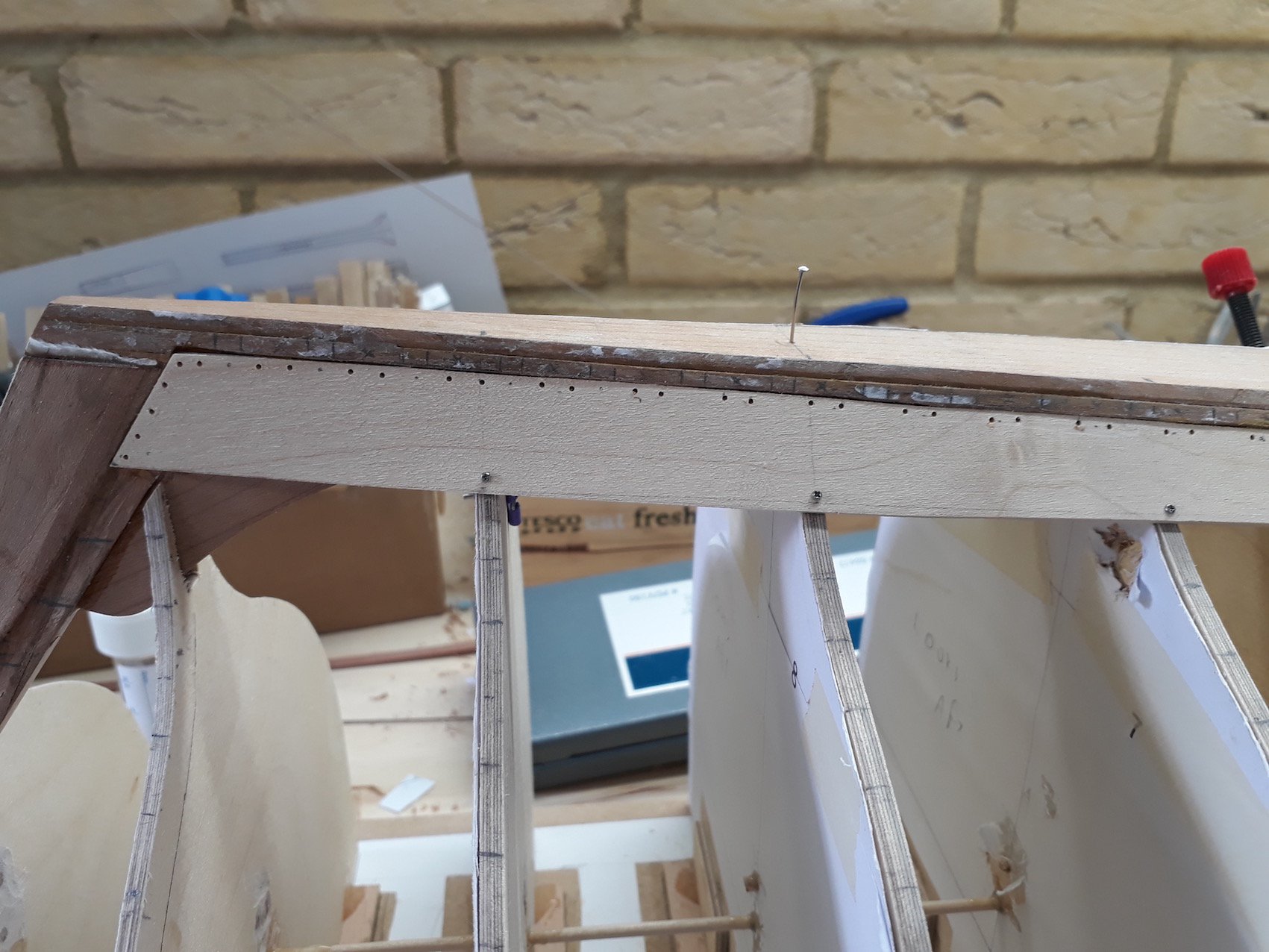
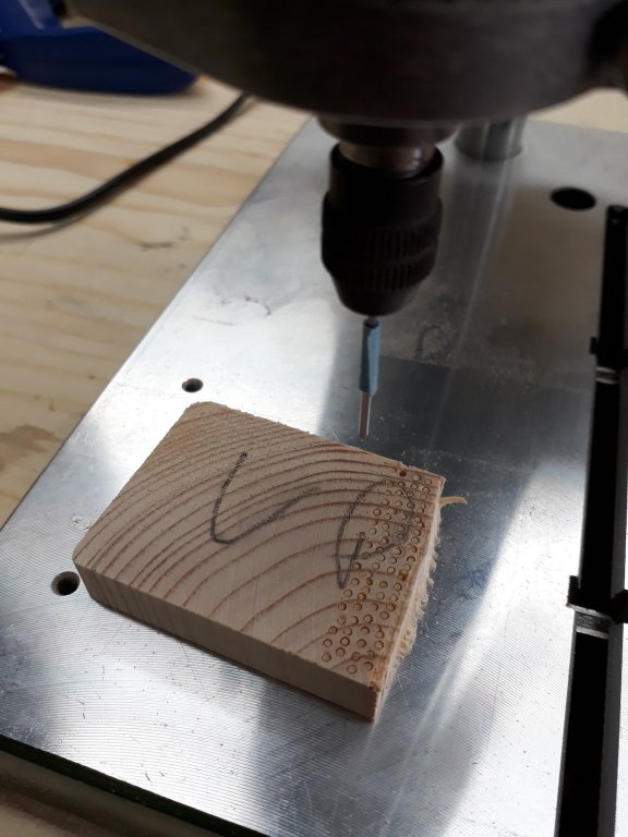
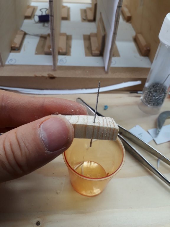
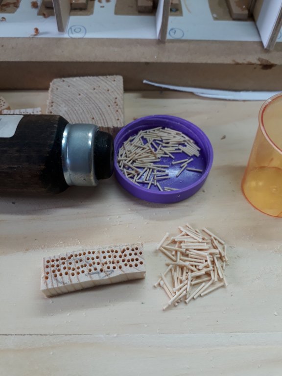
Dear all Slowly the boat is progressing. Both GB planks seem to fit reasonably well. Steam bending in the kitchen worked just fine, both planks very easily took and maintained their bend with minimal effort and no mess in the kitchen at al I glued the port GB plank with PVA glue, I wonted to avoid the messy epoxy. I will also put tree nails where the plank rests against the keel, sternpost and stem and 1 mm screws at the temporary frames. I will need a lot of tree nails, as later they will be used to secure the steam bend frames to the planks. My method for mass producing tree nails works fine. I have a selection of needles but I think i ll use 0.8 mm tree nails at the keel and 0.9 mm for the frames. Tomorrow I will glue the other GB plank and tree nail and screw everything together, The hull will be much stronger then. Regards Vaddoc

-
I use the big bottles of epoxy and insulin syringes as you can get very accurately just 1 m of each. If I need more epoxy I use 3 ml syringes (without the needle). I wear single use gloves and of course use the syringes only once. Very consistent results and not messy at all. Better value for money also I think It is important to avoid skin contact with epoxy as an immune response builds up over tine.
-
Either way it is not possible to store your details on their site, every time i buy something I need to enter all details al over again. But it is safe, I ve used it many times
-
A new lesson learned today. The garboard planks need to fit perfectly buy also need to be symmetrical! This is not so easy when the wooden keel and rabet are not truly completely symmetrical. I took me 5 tries to get the gb planks shaped to be just acceptable. That was a lot of expensive wasted wood! At least maple is much easier to sand than pear or cherry wood. 6 Next, the planks will need to be secured in place. I am thinking of using a tiny amount of epoxy (as the slots for the ribs should not be filled) and tree nails with PVA glue. Since the frames are temporary and will be removed, I will use also 1 mm micro screws at the frames. The planks will need to be steam bend somehow, not sure how this will be done. I suspect the solution lies in the admiral's kitchen utensils.
-
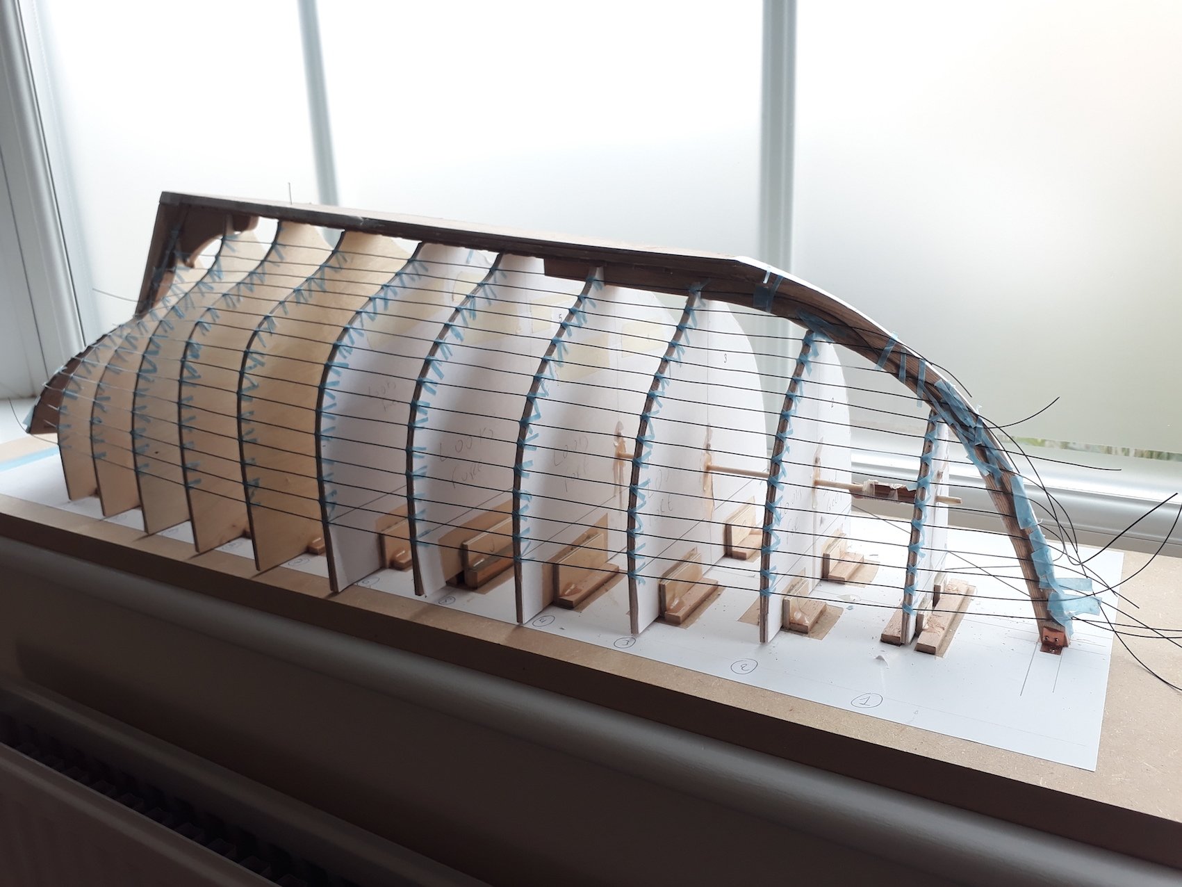
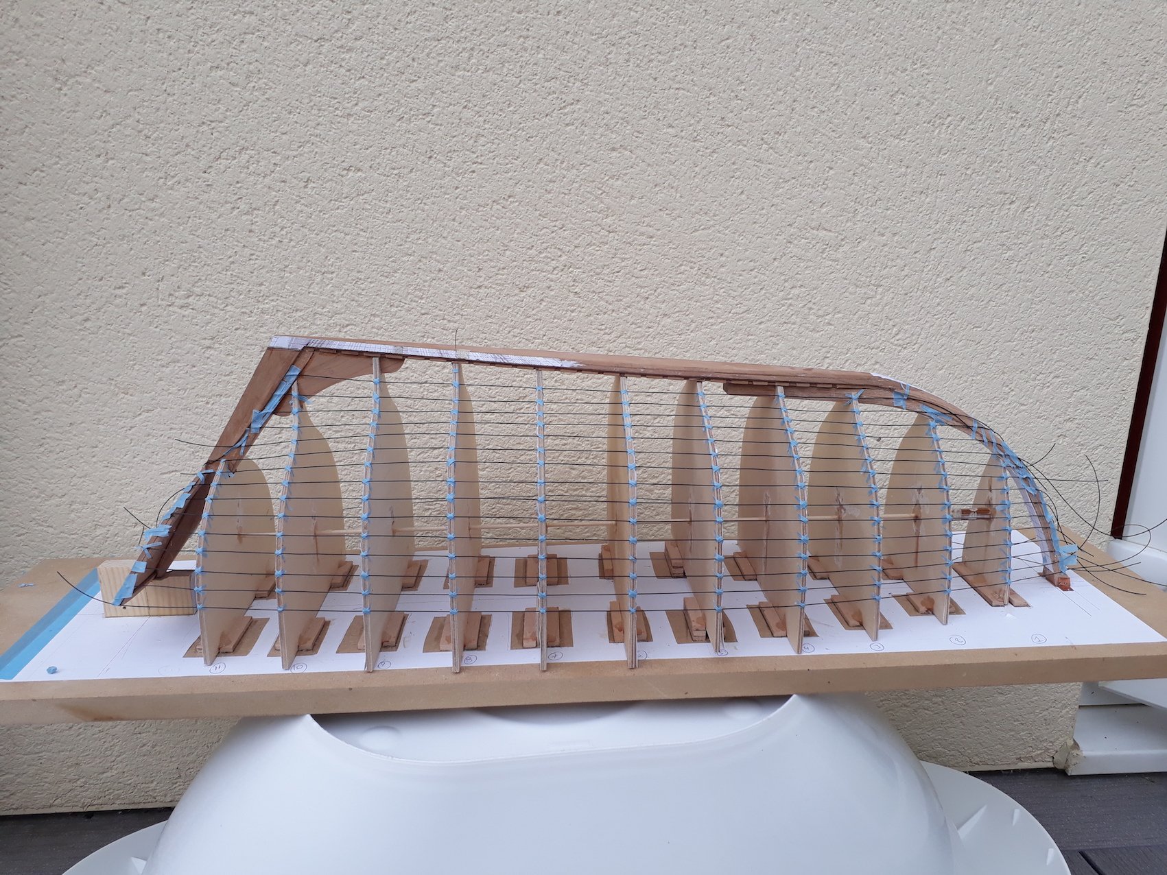
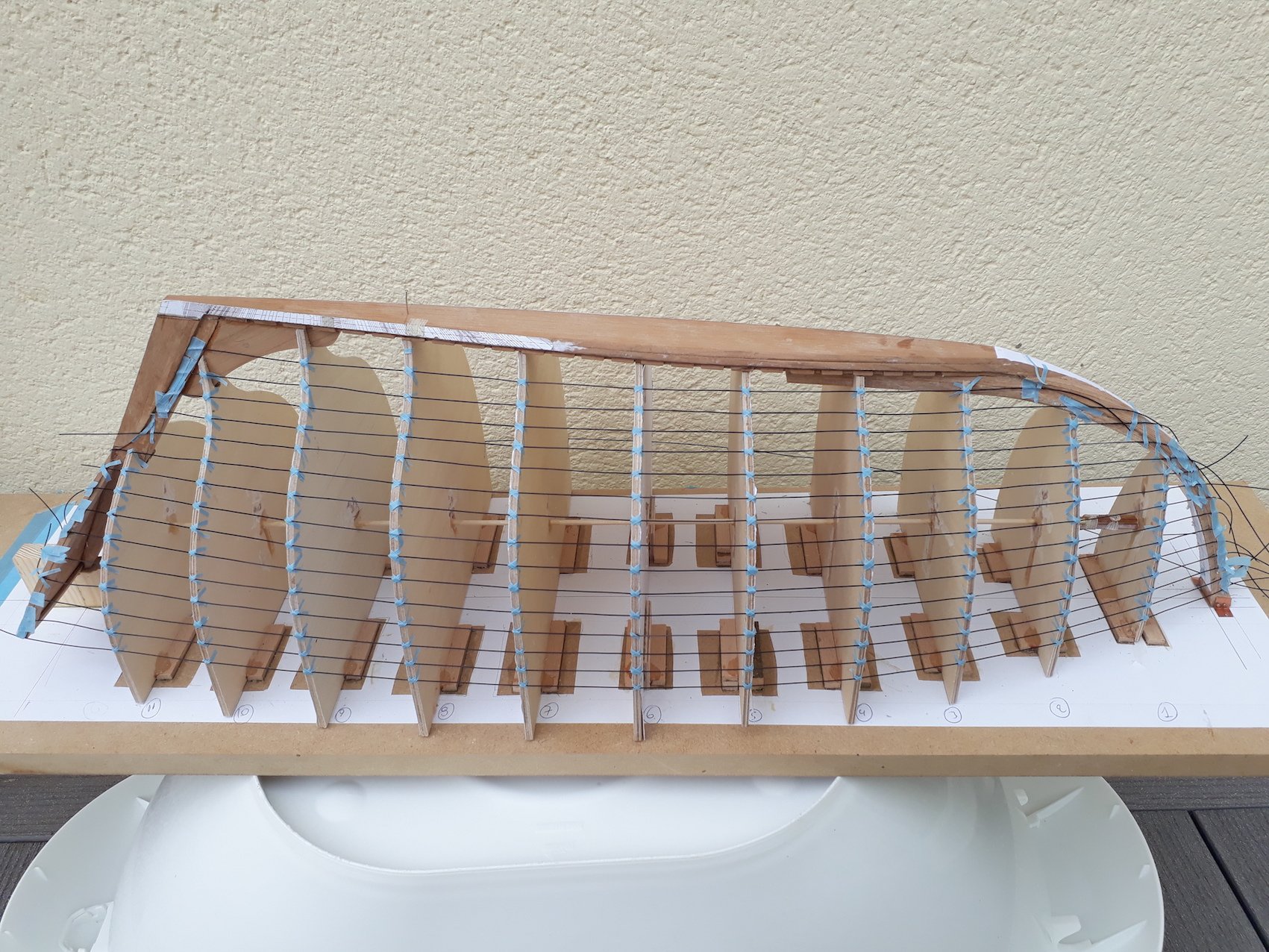
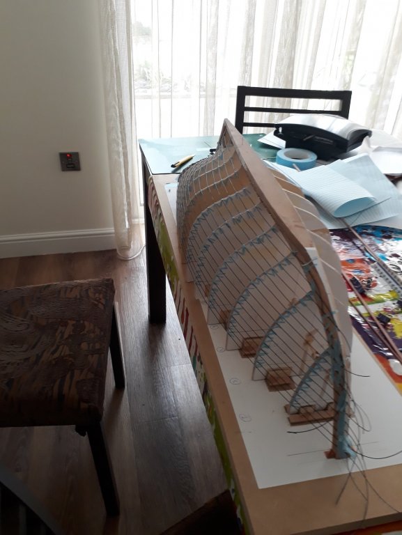
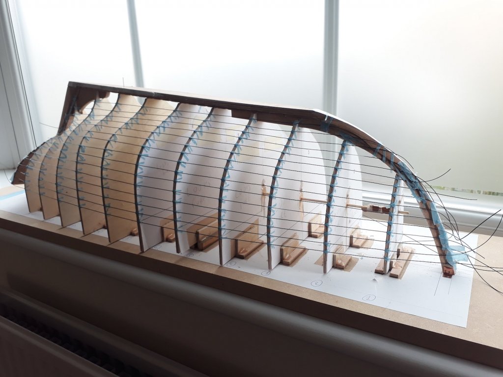
The outlining of the planks is finished! It looks pretty close, certainly not perfect. I think it will need a lot but not unreasonable spilling and I wonder if I have enough (expensive!) maple sheets, considering that it took me 3 tries to cut the gb planks to shape. The black fishing line is unfortunately too thick and strong so it distorts the lines but they will be faired again when cut. I am sure it can be done better but I think I ll leave it as is, after all the shape of my hull is far from perfect. Some times better is the enemy of good.


-
I did some more work on my planking and this time I played with a batten. The batten I used was pear wood, very stiff wood, very straight strip, 2 x 5 mm. Really does not want to bend sideways. I realised I couple of things: 1. If you place the baten so that it lies flat on all frames, it will start low at the stern and end up very high at the bow, which is of no use. 2. I you bend the baten so that it touches all frames just with one edge, lifting the other edge, and mark the contact point at all frames, you get a fair graceful curve. This can be modified to start and finish at different points at the bow and stem so that it does not dive down or points up very high. Always allow the strip to lift and bend freely, making sure always it touches all frames with an edge. 3. If the first try is near the middle of the frame mid hull, we know that half the planks will need to be placed above and the others bellow, so the starting point at the stern and the finishing point at the bow can be selected so that all planks have enough space. 4. The amount of spilling needed appears proportional to the lift the edge of the baten will have 5. This way the hull can be divided to as many sections as needed, and even the width of the plank can be different for each section (This is advanced planking I think) 6. The Garboard plank will need to follow the curve and shape of the baten when general outlining and division to sections is completed, the only thing then to decide is how wide and how high up the stem it can go. This is a photo of my hull, it was done just eyeballing it and I think is close enough. I used the baten on the other side but gave me pretty much the same result.

-
Eddie, this deserves the "doing something in the most possible complex way" award! In the end you also need a lathe and have only 5 min to thread the valve before ammonia consumes your house! It reminds me of this annual competition for the most purposeless scientific research. Still, it works. Regards
-
I used epoxy for securing hinges. I degreased the metal and I think also lightly sanded the meeting surface. Really strong bond
-
You have done a brilliant job and the two boats look identical, somehow though your boat looks way more of a fun place to be. Loved your sunbeds!