catopower
-
Posts
1,901 -
Joined
-
Last visited
Content Type
Profiles
Forums
Gallery
Events
Everything posted by catopower
-
 Hey Chuck, Don't know how it is on the wooden kit, but on the card kit, don't add the rudder until the build is done. The straps are just too delicate and any small bump can knock the rudder loose and tear out hinges. My rudder has taken quite a beating 🤨
- 130 replies
-
- 1
-

-
- wütender hund
- hanseatic
- (and 2 more)
-
Chuck, more nice work. Did you make the bug or was it included in the kit? It's all looking great. Did you run into the same issue that I did on discovering the bow support structure thingies late in the build?
- 130 replies
-
- 2
-
-
- wütender hund
- hanseatic
- (and 2 more)
-
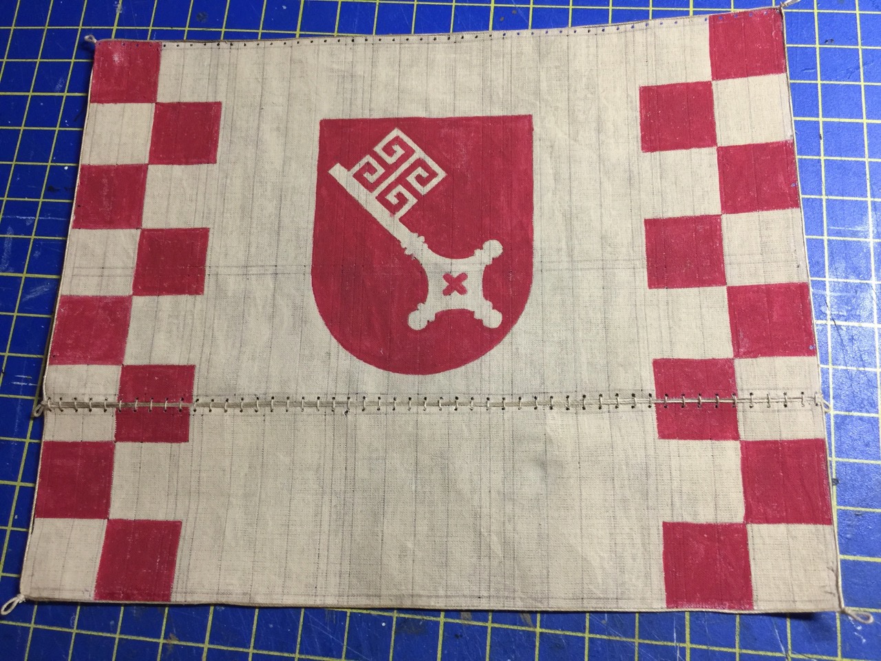
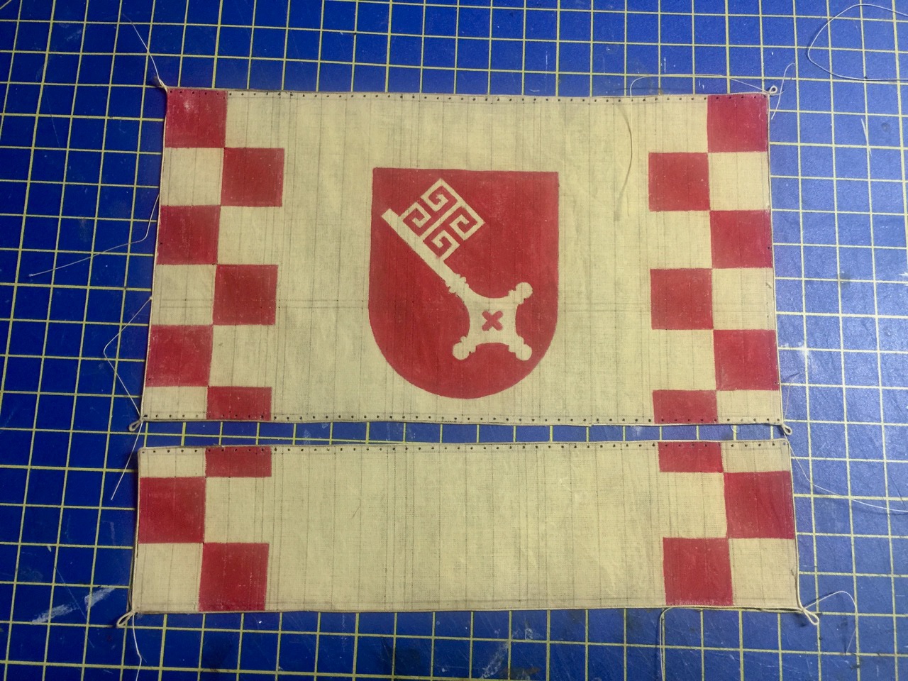
Thank you Steven, Druxey. I've been particularly enjoying this part of the build, mostly because the sail provided in the kit does turn out so nicely. It's painted according to the kit's instructions and I think the laced bonnet is a nice detail too. I've been dragging my fee on a rigging project, so I think this is going to help me get back into a proper rigging mode. At least I hope!
- 175 replies
-
- 1
-
-
- hanse kogge
- shipyard
- (and 1 more)
-
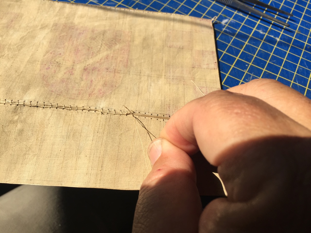
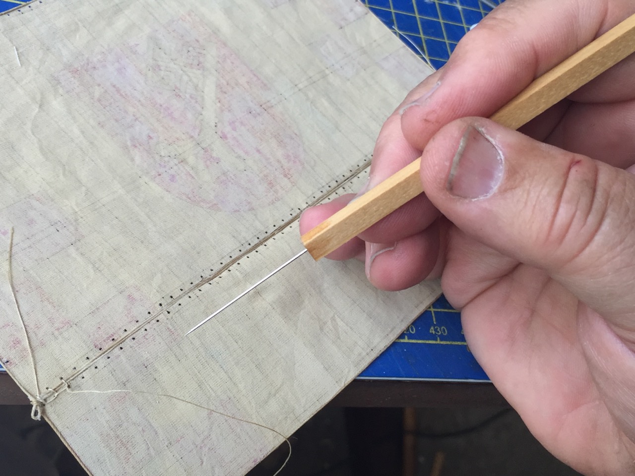
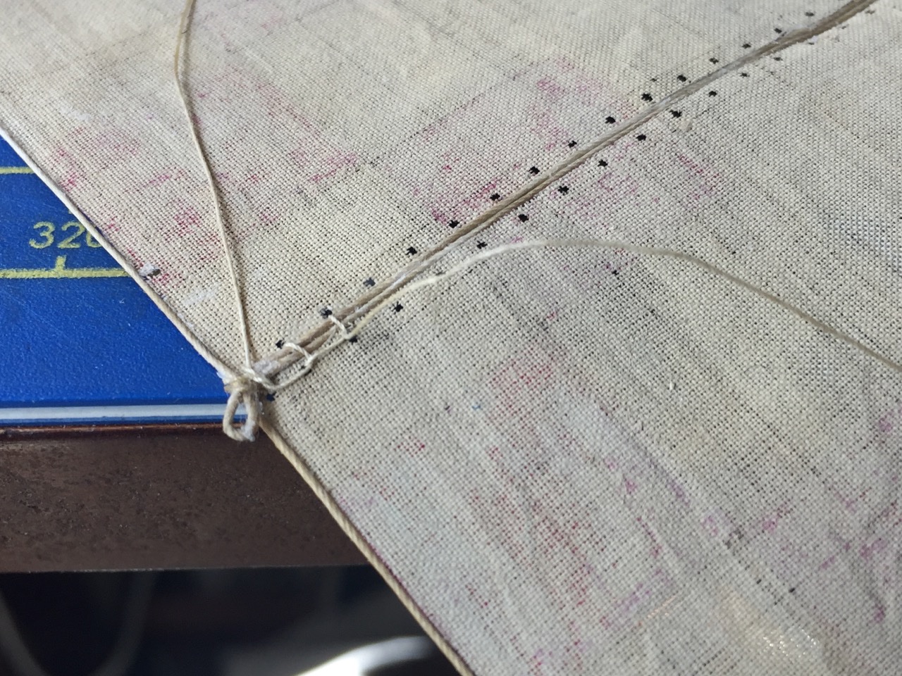
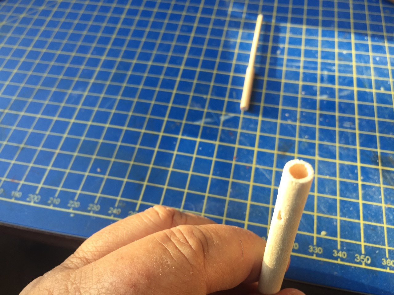
Well, today, I laced the bonnet to the main sail. Took quite a while. Felt a little burned out, like when I'm tying ratlines for an hour. But, it's done, and I'm pretty happy with it. I found it necessary to poke open some of those holes with a sewing needle, so I decided to make a new "Ship Modeler's Marlin Spike" with a sewing needle glued into a wooden handle. Later, I ground open the eye of a needle and glued it into the other end of the handle to use as a kind of line grabber. And the laced bonnet in place... Now, I just need to shape the yard and then lace the sail to it. Should be able to do that and to step the mast and start with the standing rigging this weekend. By the way, for those wondering about my Woody Joe Kitamaebune model, in between steps, I'm building up the sail from individual panels. I'll be posting something on that build log soon. I'm pretty determined to get both these projects done very soon. I have a third small project that's I didn't create a build log for, but it's close to being done too, though I'd started it a few years ago. I'll post photos in the gallery of it when it's done.
- 175 replies
-
- 7
-
-

-
- hanse kogge
- shipyard
- (and 1 more)
-
Rope-where to go since Syren is no longer making it?
catopower replied to bear's topic in Masting, rigging and sails
Getting back to the original topic, which is about what sources there are for finished rope, I have to say this looks very nice. Thanks for the post MESSIS. -
Chuck, that's the way the sails came. The holes are nice and clean and I think I might be able to run the rigging line through them pretty well without having to enlarge them. Of course, I'll dip the tip of the line in CA first to harden it and then cut it sharp. But, I don't think they're really any larger than the diameter of a small sewing needle. I guess we'll see how they look when line is laced through them.
- 175 replies
-
- 3
-
-
- hanse kogge
- shipyard
- (and 1 more)
-
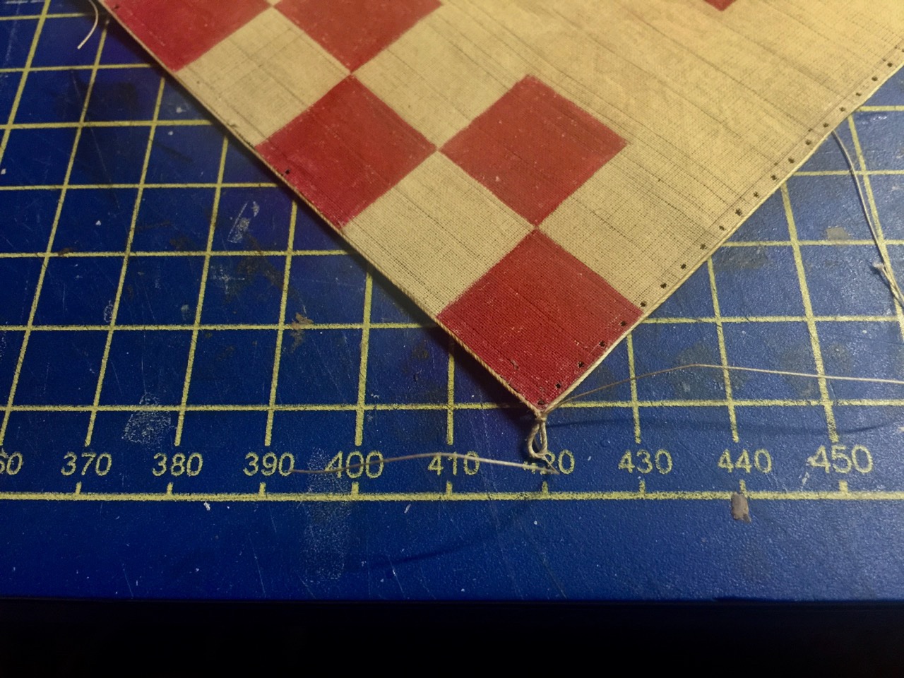
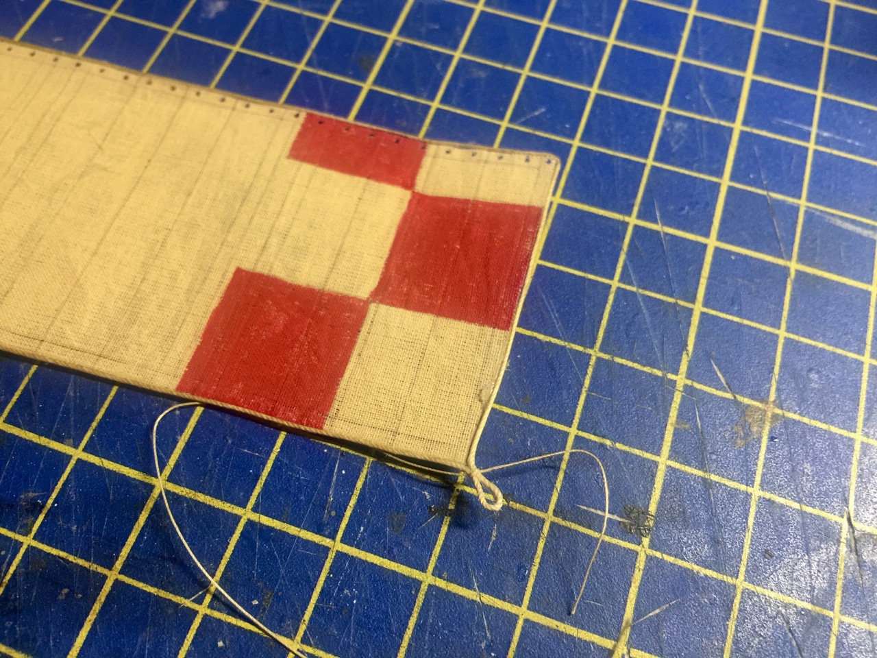
Working on the sails a bit today. Finished adding the boltropes. The line for this is just glued around the edges of the sail and bonnet. Shipyard does a very good job with sails. It seems that they laser-etch the seam lines into the cloth. My HMS Alert kit was the same way, and I was really happy with the results I was getting from working with the sails for that model. I'm looking forward to lacing the bonnet into place and lacing the sail to the yard. I just have to finish shaping the yard first.
- 175 replies
-
- 4
-
-
- hanse kogge
- shipyard
- (and 1 more)
-
Unfortunately, I seem to have misplaced my double secret decoder ring... I guess I have to start looking for specially marked cereal boxes again.]] Well, it's actually just a mast with couple shoulders for seating of shrouds and such. I think it's just that the change in mast diameters at the shoulder is a bit extreme. That, and maybe the "blocky" shape of the mast.
- 175 replies
-
- 3
-
-
- hanse kogge
- shipyard
- (and 1 more)
-
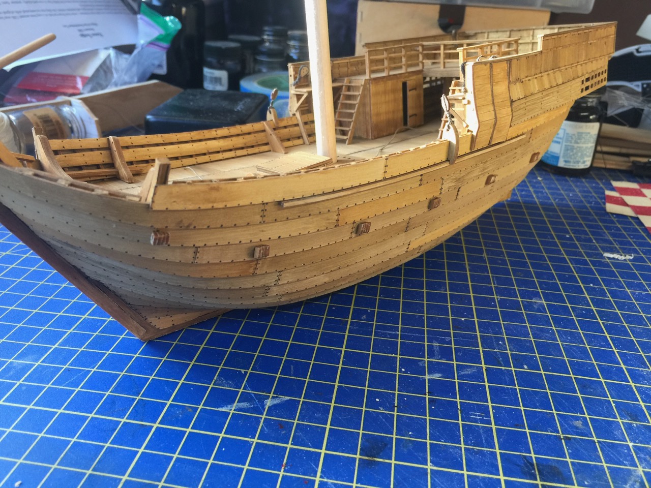
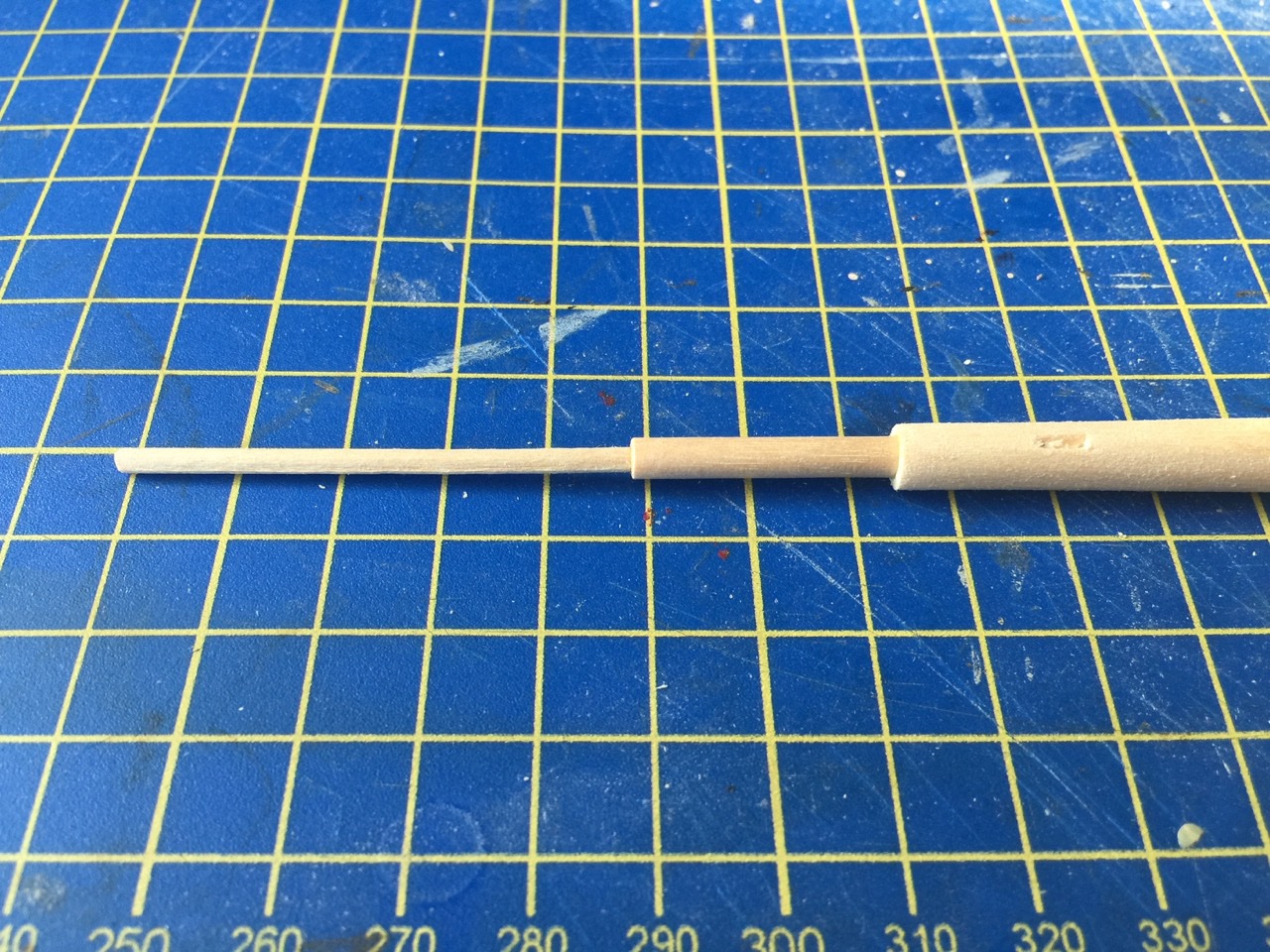
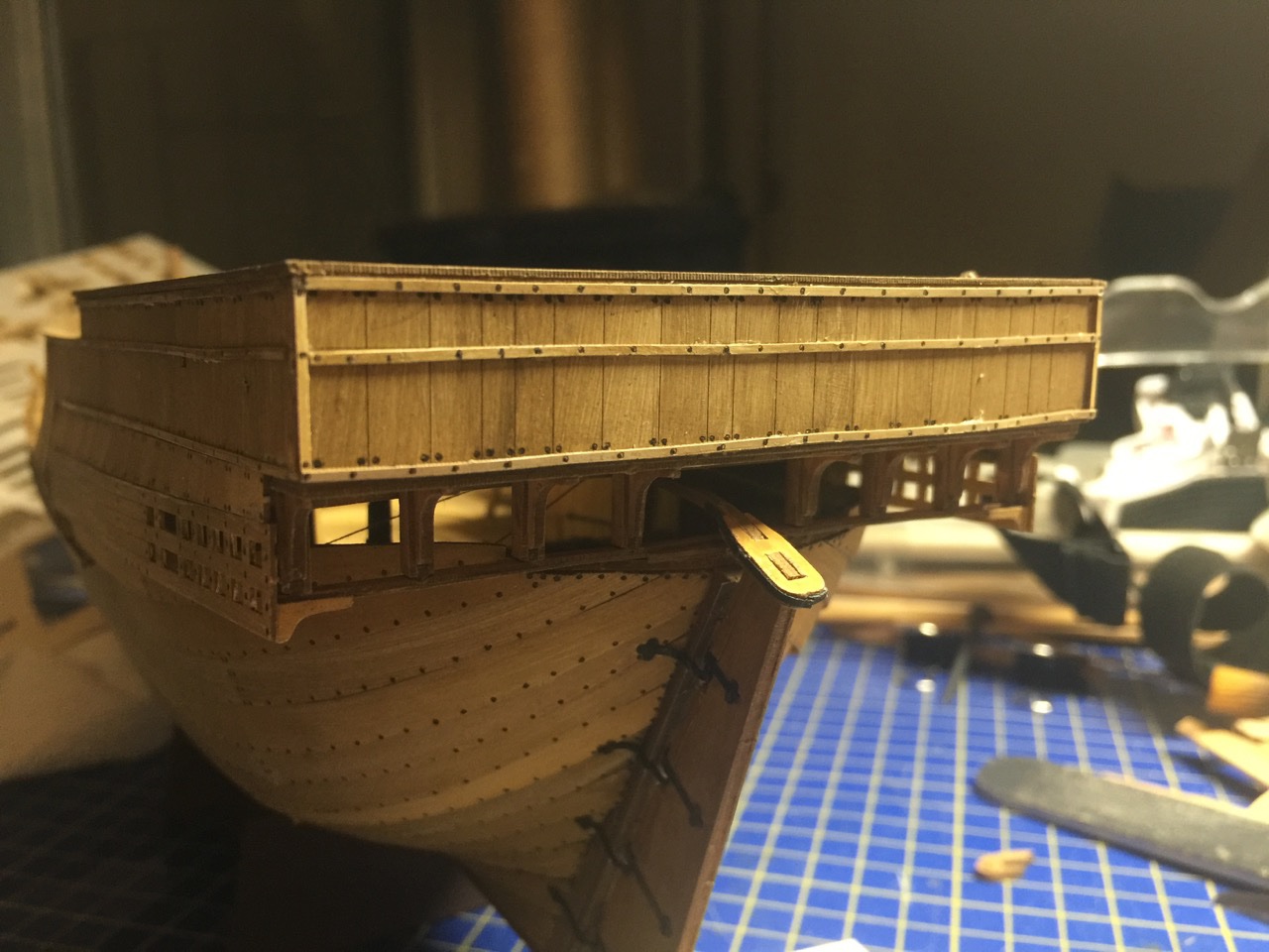
Well, at least I'm at the point where I don't think I have to worry about mislabeled parts, etc. I managed to get those fiddly beam ends together and mounted. Unfortunately, the insructions don't really make it clear about the pieces for the forward most set. For those, each piece is a slightly different size, so that the final assembly has a certain angle to it. Problem is, they don't point out that the pieces have to be stacked in one order for one side and a different order for the opposite side. Me, not being smart enough to think about this in advance, managed to stack both sets the same way. So, I ended up with two "left shoes", as it were. I managed to deconstruct one of them and re-assemble it in the proper order. Wasn't ideal, but it worked out okay. You can see the layering in the "beams" glued into place below. I'm going to paint these to try to hide that layered appearance. You can also see the base of the mast, which I test fit into place. The mast is supposed to have three distctively different diameters to it. Rather than turning down a single piece or trying to otherwise cut the dowel to shape, I went the route of drilling out the ends of the lower pieces and fitting the upper masts into place. I've done something similar in order on antoerh model in order to join two different kinds of wood into a single mast, and it worked out well enough, so I tried it here. Of course, I still have to stain the wood, though I think the instructions call for painting it. Also there's a mast truck I need to mount at the top, mast coat at the base, and a spider band. Those are all provided as laser-cut card stock.

- 175 replies
-
- 7
-
-
- hanse kogge
- shipyard
- (and 1 more)
-
I saw someone had posted a questions elsewhere about a Black Pearl kit. It was a Revell plastic kit and had the official Disney logo on it and all. Does the Zveza kit actually have Disney licensing?
-
Chuck, I'm also now at the stage where I am understanding why you decided to add real beams through the hull planks. I think I'm going to be okay with the kit's built-up beam ends, but it's a lot of little bits. Shipyard recently came out with a third wooden cog model kit. It's the Hanse Kogge von Bremen – same as the laser-cut card model I'm working on. But, interestingly enough, it's noticeably more expensive than the other wooden cog kits. Please keep going on your build – It keeps pushing me along to finish mine! And thanks! 😁
- 130 replies
-
- 1
-
-
- wütender hund
- hanseatic
- (and 2 more)
-
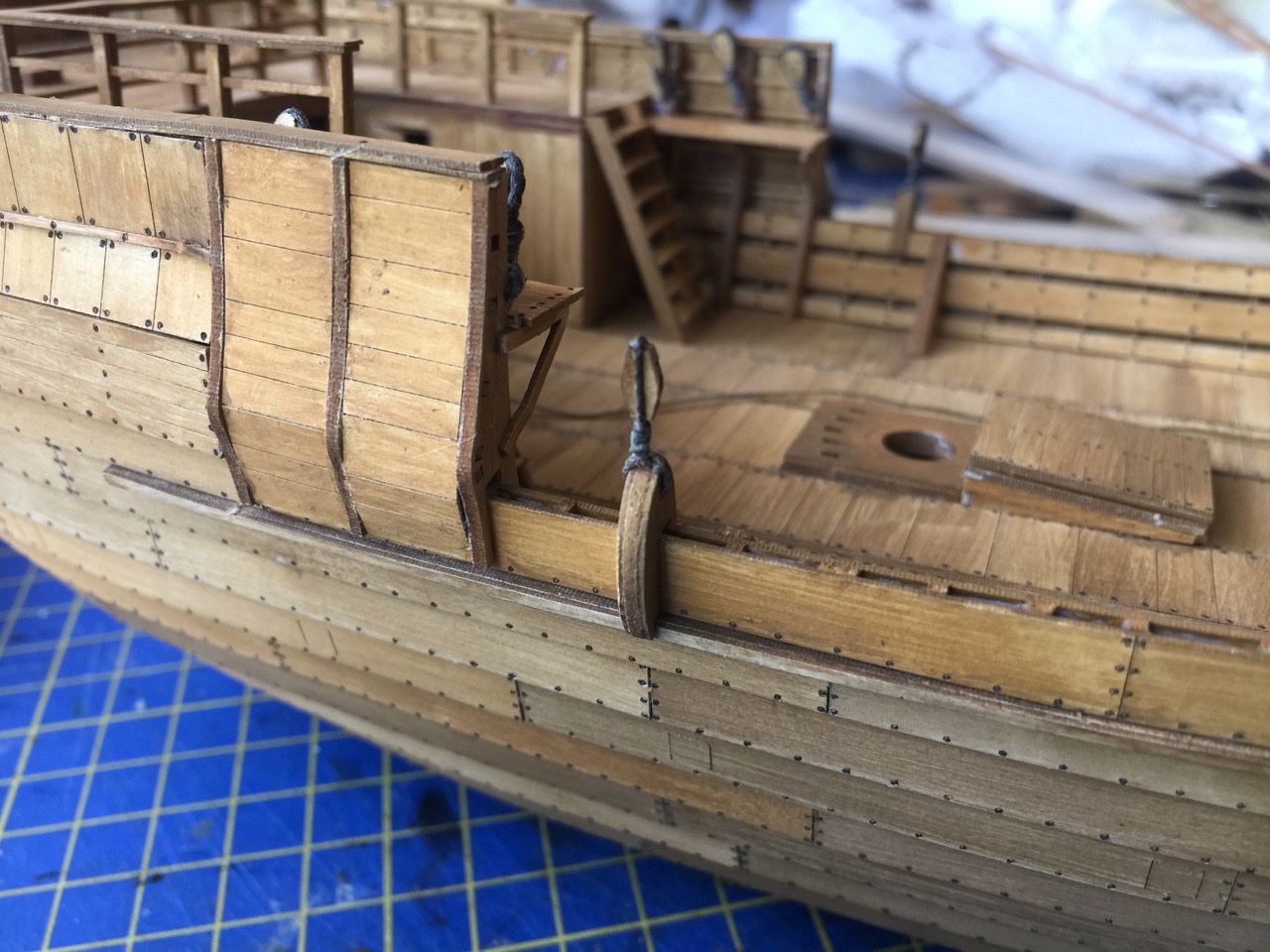
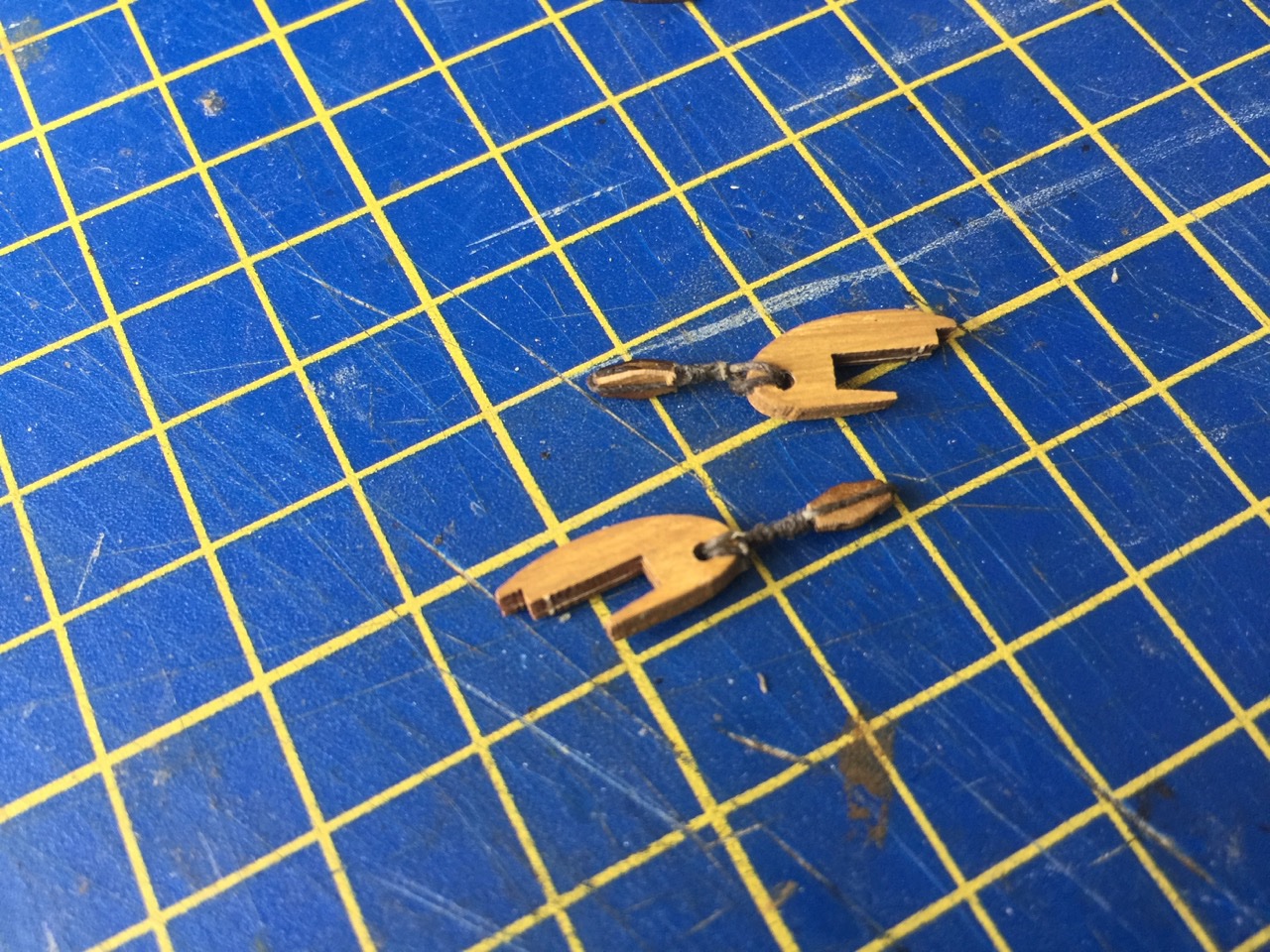
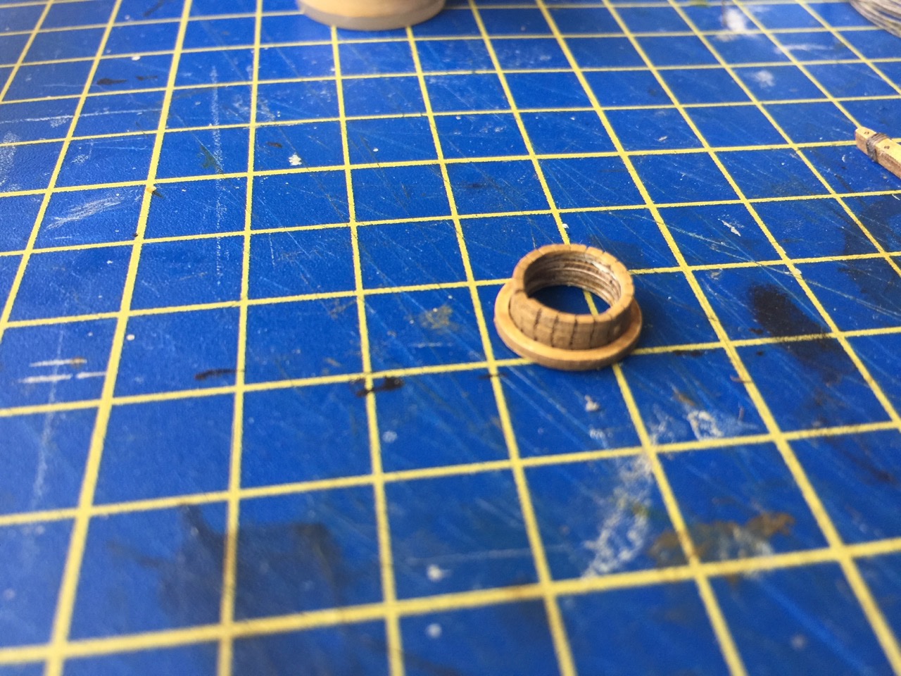
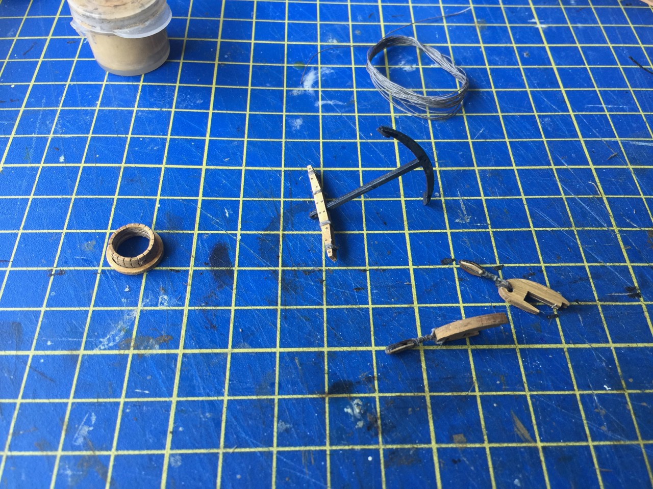
Trying to make regular progress on the Bremen Cog. More doo-dads done and I started dying the line for the sail. The Shipyard kits include linen rigging line. It's very nice, but it's white. So, I've started staining more of it, most just enough to deal with current steps. I think I'm caught up on the "extra" parts I'm finding. I did discover that the instructions completely missed one set of parts that I found still on the parts sheets. These are what I might just call trim pieces or battens that fit on the aft side of the stern castle. The parts can be seen in some of the instruction photos, but they're never labeled to show you where they go. And as for the doo-dads, here are mast coat, anchor, and some pieces that mount to the hull for the attachment of the backstays. It's really pretty interesting how detail oriented these kits are. More so than most wooden kits I've seen (except for maybe the wooden versions of these cogs). If you look closely at the mast coat, it's actually built up from several laser-cut hoops. Most are cut and lined up so that they look the coat is made up many wedges, though mine look like they're leaning a little. But, the top hoop is laser engraved on the top face, so that it looks like the ends of the wedges. The engraving make this piece pretty delicate. Two larger hoops at the bottom complete the assembly. In all, the mast coat is made up of 8 pieces, and an expert modeler would have gotten the laser-cut details lined up perfectly so that the wedges didn't lean like mine do.
- 175 replies
-
- 9
-
-
- hanse kogge
- shipyard
- (and 1 more)
-
How to simplyfi the build of a large ship?
catopower replied to ubjs's topic in Wood ship model kits
Hi ubjs, maybe you're like me. I enjoy building hulls and I too like planking a lot, so I have a few hulls sitting around of various ships. Some are solid hull, some are plank-on-bulkhead, some are from kit, and some are from scratch. Eventually, when I finish a project, I look back at the various hulls to see if one of them speaks to me and asks to be turned into a finished model. Or maybe just to be more further toward completion. But, sometimes, it's more a matter of the dream of completing the model. I imagine how much I'd like to complete a kit, then I acquire the kit, get part way through it, but then I get a little stuck. Then a new, pretty model kit comes along, and it's too temping to switch to that one instead. I don't know if this is the case for you, but it's easy to get caught up into it, especially when you have enough financial means to acquire the kits. Personally, I'd suggesting taking one of the simpler kits you've started to completion. Then, come back to this Vasa kit. Then, you'll get more experience with the detailing of the wooden model kit, and some of the issues you will face on the smaller model, and more quickly overcome them. But, it's completely up to you. You have to build what you enjoy building! Heck, what's another planked hull in the grand scheme of life? 😁 Edit: As I write this, I am thinking about how I am working to finish my Hanse Kogge von Bremen card model, and my Japanese coastal transports, both in the rigging stage, while I recently cut the parts to build the hull of the cutter Cheerful, cut the backbone or false keel for the hull of the French lugger Le Coureur, and am prepping the plans for a build of the French cutter Le Cerf. I can't help it, I love building hulls. But, I do have to restrain myself often! -
How to simplyfi the build of a large ship?
catopower replied to ubjs's topic in Wood ship model kits
Hi bujs, Learn what you can and have fun. Remember that ship modeling is a personal experience and the ship model is yours to do with as you please. When you ask questions about how to do something, invariably, you'll get a range of answers that are mostly meant to help you build a ship model kit in a way that will provide you with the best looking results. When you choose a different path, many of us are always going to want to tell you things to try to get you back on that path to the best looking model. I started to post my own replies here in this thread a couple times. But, it's difficult as a long-time ship modeler to know how to encourage beginners without sounding controlling. So, I deleted them. But, there have been some good ideas here about simplifying the build. And, though you refer to the Billing Boats Wasa as a simple kit, there's a reason they classify it as an expert level kit. So, just bear that in mind. Hopefully, by simplification, you don't mean to rush the build. That may result in crooked frames, twisted hull, bulging or uneven planking. But, if understand you correctly, this is going to be something of a "sacrificial" build? That is one that you make all the mistakes on and plan to throw away if it's bad enough. Or is it that you want to really build a nice model here, but maybe less detailed? That's the only way I can see building this model in a "simpler" way. In any case, good luck with both builds! -
Welcome Matey0143! I agree with Chris on the Mastini book. Another book, while a lot of the company specific address references are dated, Ship Modeling from Stem to Stern by Milton Roth was an old classic, and much of the technique information applies, as do discussions on scale, rope sizing, and so on. It was actually the first ship modeling book in my library when I was starting out. Of course, the fact that that was over 16 years ago indicates just how dated those the company references are (for paint suppliers, tool suppliers, etc). Probably, the one book that I truly consider my ship modeling bible is the now-out-of-print Historic Ship Models by Wolfram zu Mondfeld. Not a how-to book, but a great reference for modelers, chock full of information. Good luck with your build and enjoy!
-
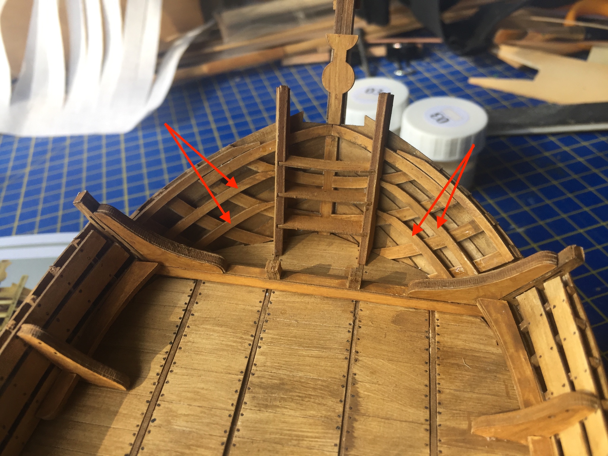
Card model making, with its large numbers of parts and limited instructions, resulted in another discovery the other day. I found some parts on a sheet that look like something I should have used by this point. So, I went back and checked the part number, then hunted through the instructions again to find that the parts were referenced many pages earlier. Gotta spot the little numbers in one of the photos. I realized it's a bit like finding Waldo... But, adding the parts at this stage was no problem. There are still plenty of parts and I'm approaching the end of the main build. So, I'm hoping I haven't missed anything else. Or, more appropriately, I hope I haven't missed MUCH else. In the photo below, I marked the forgotten pieces with red arrows. With that mystery solved, I also assembled the railing at the stern castle. That's another 27 parts on the model... There are a few more do-dads to go on the model yet. But, I'm kind of itching to do some rigging, so while I'm dealing with these things, I'm also prepping the rigging material and getting ready to detail the sail.


- 175 replies
-
- 5
-
-
- hanse kogge
- shipyard
- (and 1 more)
-
Druxey, thanks for the possible explanations. It felt like I'd been working on this project since before Covid, but I just looked and I'd started it just about a year ago. So, thanks! I'll blame it on "Covid Lockdown Brain", though advancing years may actually be the true culprit. Anyway, I just came out of quarantine, which I had gone into due a client I saw recently having gotten sick, then diagnosed Covid positive(!). Fortunately, their symptoms have been mild and I've come through testing negative. So, all is sort of well. Gave me more time to deal with ship modeling projects. Only problem is that the weather here has been gorgeous, and my cat is seriously distracting me with her shows of "cuteness".


- 175 replies
-
- 7
-
-
-
- hanse kogge
- shipyard
- (and 1 more)
-
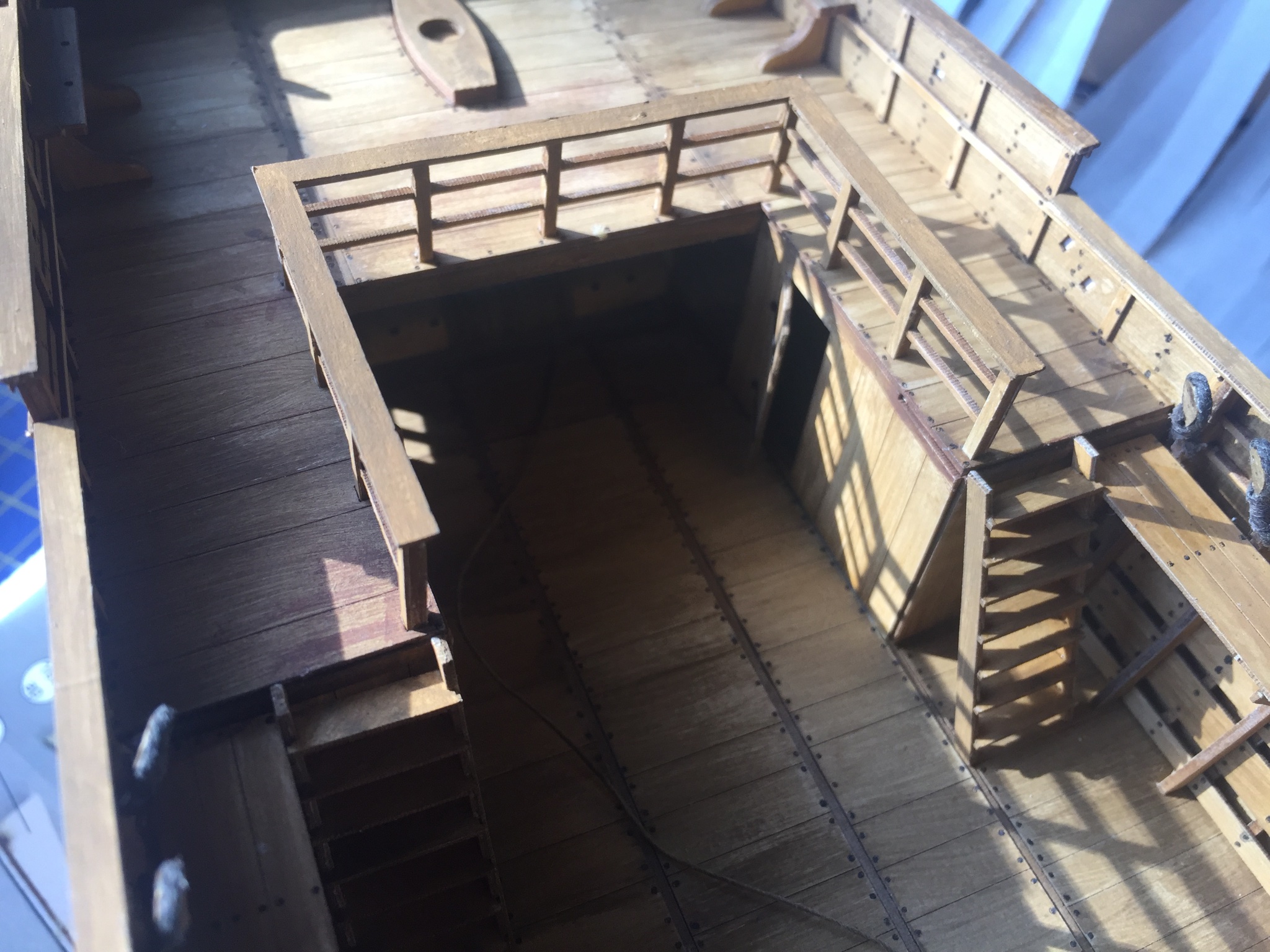
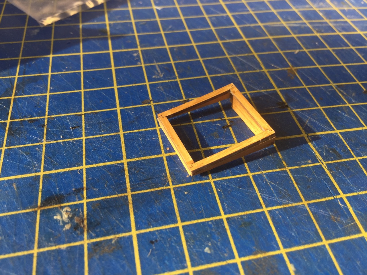
Hi Chuck, Well, that's the whole thing. I didn't install the hatch coaming because I had somehow convinced myself that I lost the parts. So, I just pressed on, not to be held back by it, figuring the lost hatch coaming might turn up. Then, it sort of did, right in the parts sheets. I wonder if there might be leprechauns or gremlins messing with my mind? 🤔
- 175 replies
-
- 3
-

-
-
- hanse kogge
- shipyard
- (and 1 more)
-
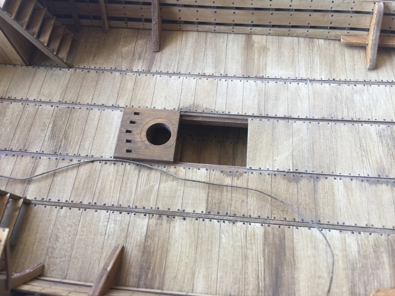
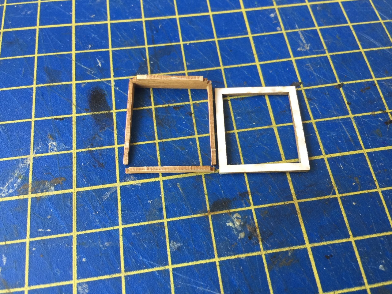
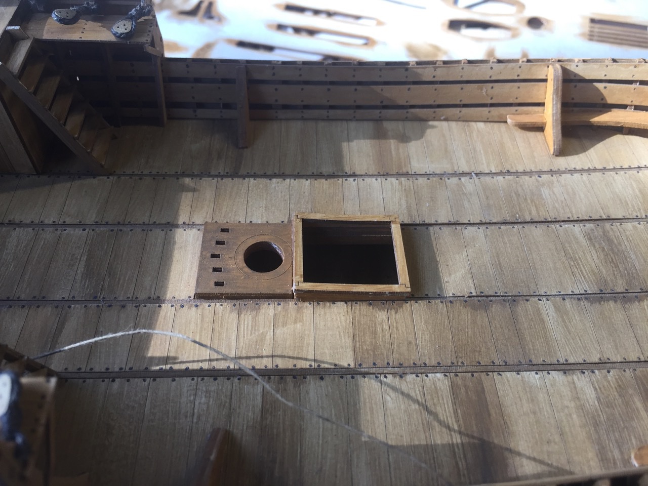
After looking in on Chuck Seiler's Wütender Hund builds in card and wood, I'm inspired to get my own cog project completed. But, I had one of those bewildering moments today regarding this project that's making me question my sanity... You might have noticed that there is still a big opening in the center of the deck. Way back in the build, around the time the deck was laid, there was supposed to be a coaming put in place around this opening, just forward of the mast. Now, I skipped this step for a long time because I was sure I made the coaming and misplaced it. I finally figured I must have accidentally put it into a stack of things to throw out. 🤨 For the longest time, I had resigned myself to the idea that I'd have to make a new coaming from scratch. So, today, I was back to working on the model, which is pretty close to completion, so the number of parts remaining on the sheets is dwindling. Then, I noticed some parts on the sheets that seemed curious. I looked for them in the instructions and, lo and behold, here were the parts for the hatch coaming! It seems that I never actually did construct it. My recollection was completely wrong. I can't imagine how I could have ever thought I'd lost something I never built. Apparently, I'm losing my mind! Well, I finally put the parts together, and now have a completed hatch coaming on deck. I don't think I've recovered my sanity, and I may not any time soon, but at least my model is one step closer to completion.
- 175 replies
-
- 7
-
-
-
- hanse kogge
- shipyard
- (and 1 more)
-
Need help from a model maker in California !
catopower replied to Ekis's topic in Wood ship model kits
Hello Ekis, I got your PM with all the info. But, If there is someone here who lives in the Santa Barbara area, that's probably best. If not, I'll see if there is something I can do to help! -
Need help from a model maker in California !
catopower replied to Ekis's topic in Wood ship model kits
Hello Ekis, Sorry to hear about the model damage. That's very saddening. It's difficult to find a way to ship models safely. I don't think I'm the person to help you out, I live up in the San Francisco Bay Area. But, my elderly mother lives in the northern part of Santa Barbara county, and I do have to travel back and forth a bit as I'm in the process of selling the family house. If you don't get any good responses, send me a PM. I also have modeler contacts in Ventura and San Luis Obispo areas, which are neighboring counties, an hour away from Santa Barbara, and maybe they can help find someone for you. -
Hi Chuck! I haven't peeked in on either your Cardy Dog or Woody Dog builds in a while. Woody Dog looks really good with the staining you did. It's also nice in that it seems to bring out those laser engraved nail heads. I've been busy with various things, but I will get back to finishing my Bremen Cog shortly. Your build is giving me some inspiration!
- 130 replies
-
- 2
-
-
- wütender hund
- hanseatic
- (and 2 more)
-
I can tell you that, he does. Maybe not the conversation specifically, but about considering the Surprise. He mentioned the idea to me earlier this week.
-
What were your first tools as a child?
catopower replied to FlyingFish's topic in Modeling tools and Workshop Equipment
My first ever tool set that I have memory of was a little wooden play bench that looked something like this, but smaller! After that, I don't really think I had much in the way of tools that I can recall. I was building plastic model kits, in not very sophisticated fashion. I probably just twisted parts off the sprues. Didn't use a knife blade until my dad gave me a balsa airplane model, then I needed one. I guess I did have a kids carpentry tool set that had hammer, pliers, hand drill, screw drivers, maybe a hand saw. Still, as a kid, nothing that was any more sophisticated than X-Acto knife, coping saw, razor saw – stuff passed down from my dad. Oh, and I did get his vaccu-form machine, though I had NO IDEA what to do with it...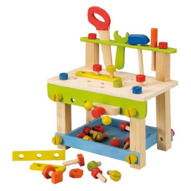
-
HakeZou, I love your Pandemic Flotilla! That's really quite a nice collection of models for one year of work. Very nicely done.
- 79 replies
-
- 1
-
-
- sergal
- sciabecco francese
- (and 1 more)