HOLIDAY DONATION DRIVE - SUPPORT MSW - DO YOUR PART TO KEEP THIS GREAT FORUM GOING! (Only 20 donations so far - C'mon guys!)
×


Dziadeczek
-
Posts
645 -
Joined
-
Last visited
Content Type
Profiles
Forums
Gallery
Events
Everything posted by Dziadeczek
-

Cutting brass sheet
Dziadeczek replied to Landlocked123's topic in Metal Work, Soldering and Metal Fittings
Put a few drops of cutting fluid onto the teeth of your blade and on the brass sheet before cutting - it makes the cutting easier, quicker and cleaner. -
Thin hull planking
Dziadeczek replied to Gerarddm's topic in Building, Framing, Planking and plating a ships hull and deck
I can cut hardwood on my PREAC saw as thin as a sheet of paper! -
Advice on work station setup
Dziadeczek replied to Paul Gardner's topic in Modeling tools and Workshop Equipment
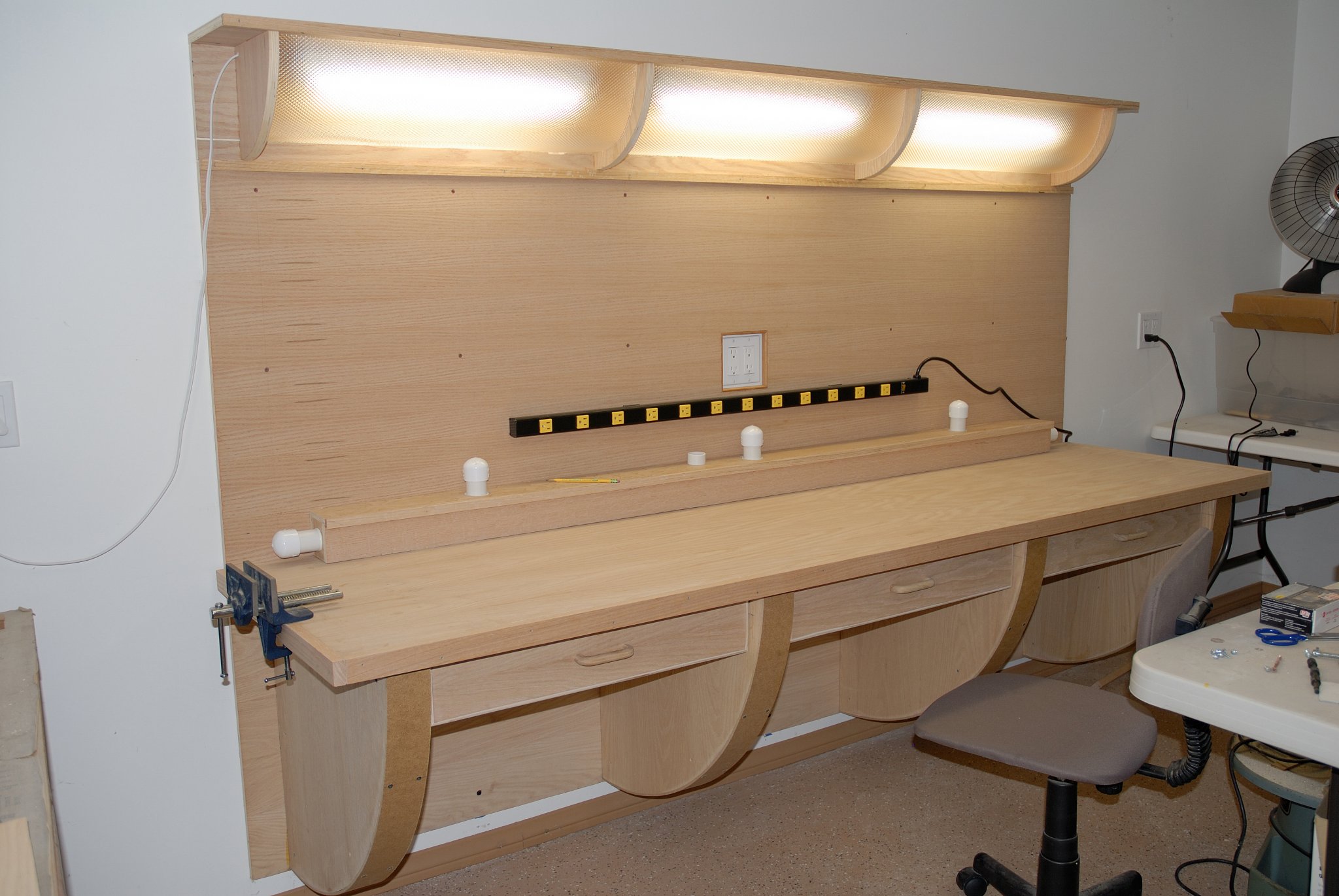
This is a setup I built many years ago, following an article in an old magazine "Family Handyman" . This workbench is about 8 feet long, permanently screwed on into the wall so it hungs above the floor and therefore doesn't have any legs, so it is easier to sweep the dirt underneath it. It has its own light sources (fluorescent tubes), a dust extraction system for your power tools and three (originally four - in the article) drawers for your loose stuff/tools and/or materials. I built only three sections (limited space), although the article shows you how to build a four sections' unit. Everything is obtainable in Home Depot or similar home centers. But, in order to build it, you must have at least basic hand/power tools, eg. full size table saw/circular saw, power drill, hammer, and so on. If you want the entire article with plans, I could find it in my junk, scan the pages and send them to you. Happy New Year! Thomas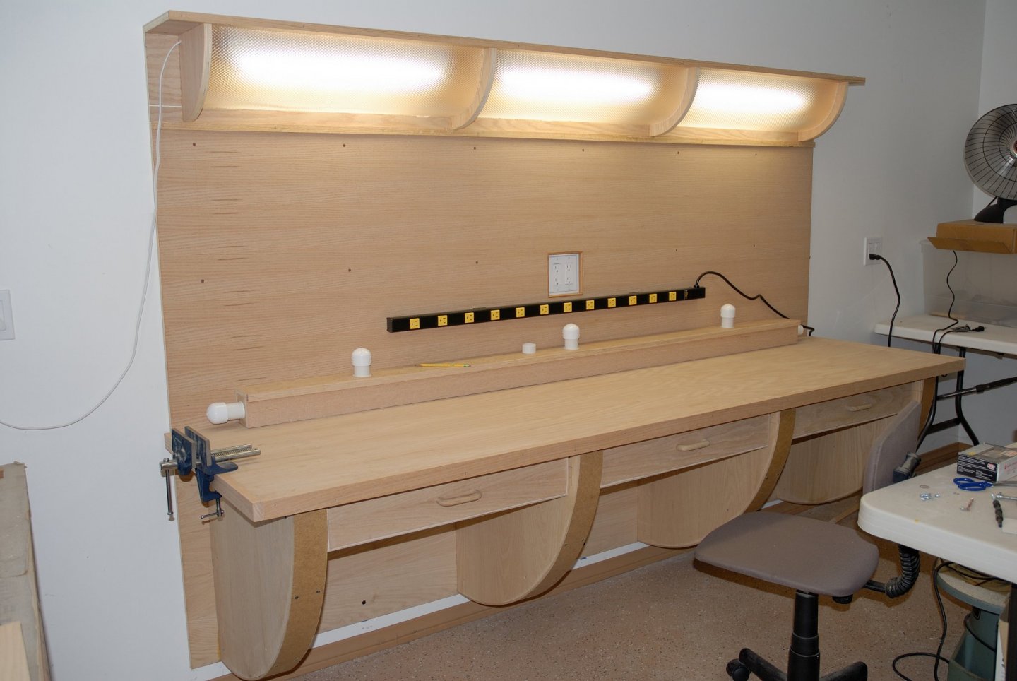
-
If it is lead you are using, how do you prevent lead corrosion on your gun barrels later on? Coat your guns with something to prevent air from attacking lead? Thanks for a very informative video! Thomas
-
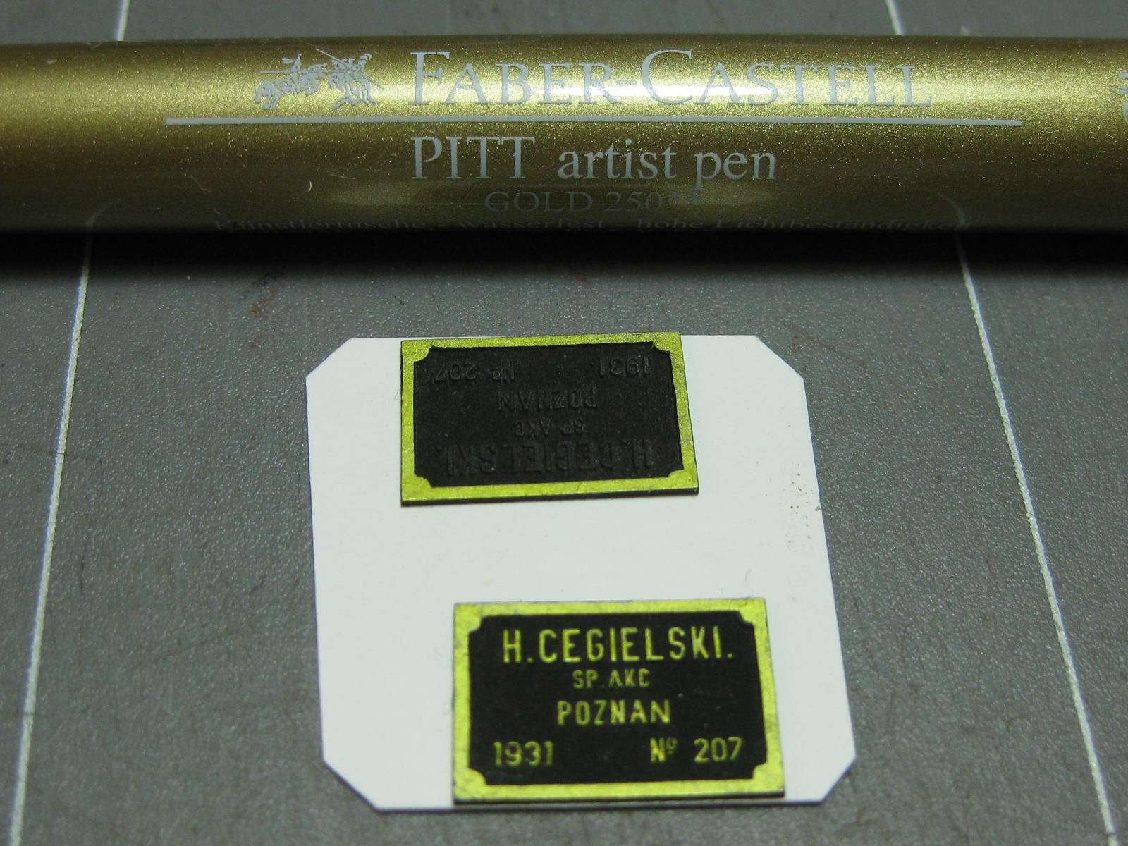
Aha, I understand. Are you building your exquisite model together with him? On the nameplate I see your name in the left lower corner, and in the right lower corner his, "Kpt. KL" Or is he just a historical/know how expert for you? Regards, Thomas
- 1,035 replies
-
- 3
-

-
- royal katherine
- ship of the line
- (and 1 more)
-
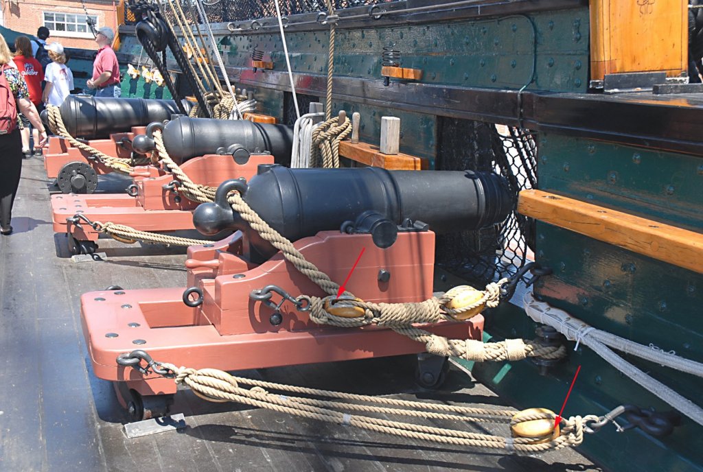
Are you sure it is a seat-of-ease? It might be it, or it might be something else... Check out this thread: (I am trying to imagine these poor souls trying to get inside that barrel in order to ease themselves, while having the "urge".... Where was the entrance to this structure? A door through the bulwark? From the top of this barrel?). Also, Druxey had a point - this thing hungs directly above a gunport, which would make the crew of this gun "difficult" to operate it during the "use" of this facility, I think...
- 1,035 replies
-
- 6
-
-
- royal katherine
- ship of the line
- (and 1 more)
-
Belay Pins
Dziadeczek replied to shipman's topic in Discussion for a Ship's Deck Furniture, Guns, boats and other Fittings
Recently I was looking for wooden belaying pins 10 mm long, but all of them were ugly and fat, not proportioned well at all. Someone had 11 mm brass ones looking OK, but it turned out they were out of stock at the moment. So, I reluctantly decided to make my own. I used bamboo skewers of appropriate thickness (from supermarkets) and prepared myself a brass former, following advice of Ed Tosti here: He is making here sprockets for his wheel, but the principle is the same. First make a former from metal (I used a short piece of brass rod, which I drilled through on a lathe. Then I filed one side to an appropriate profile for my pins. Finally I inserted skewer into the hole and using only mini files, shaped the pin to an appropriate look. This method allows for fairly quick fabrication of belaying pins and for repetition of identical shapes, which is important. -
Exquisite build of an exquisite model! Congratulations! Just wanted to make sure your plate reads "CEGIELSKI" and not "CEGIEISKI", as below. (It is a well known Polish locomotive manufacturer, even today.)

-
I'd rather paint the moulding strip first, off the model, and then carefully glue it to the model - this way the paint job is perfectly straight without any blobs and unevenness.
-
The book (vol.3) is ALREADY available. I ordered it a few days ago and it is on the way, I should receive it in a couple of days...
- 3,618 replies
-
- 2
-
-
- young america
- clipper
- (and 1 more)
-
You can make very easily and cheaply a suitable heat control gadget for your electric plank bender to avoid burning the wood. Use an ordinary household dimmer (non digital one) and a double wall socket and wire them together and mount in an electrical box. All materials available in home centers like the Home Depot, Lowes or such...
-
I would, firstly, use thinner battens (or even black thread instead - like in D. Antscherl's article). The thinner the battens, the more precise measurements you can take there. Then I would divide EACH bulkhead's edge into six (since you have six battens on each side of your hull) EVEN spaces and marked these points there with a pencil. Finally, I would affix the battens to the edges of your bulkheads exactly in those marked points. That way, you'll end up with all elliptical 'belts' - areas between the battens, from stem to stern, as being perfectly symmetrical to each other, and also on both sides of your hull, so your planks, which will go into those spaces, will also be symmetrical.
-
IMHO start with one of the simpler kits, BUT THE ONE YOU LIKE. Follow the kit's instructions, otherwise, modify and kitbash what you think you can tackle, with your skills and/or your workshop. Don't rush and enjoy the building process! You are going to have hard time however, to end up with one of your kits as a museum quality model. Not the same quality of materials and details in those kits... Thomas
-
Duplicates for Sherline Lathe
Dziadeczek replied to John Rose's topic in Modeling tools and Workshop Equipment
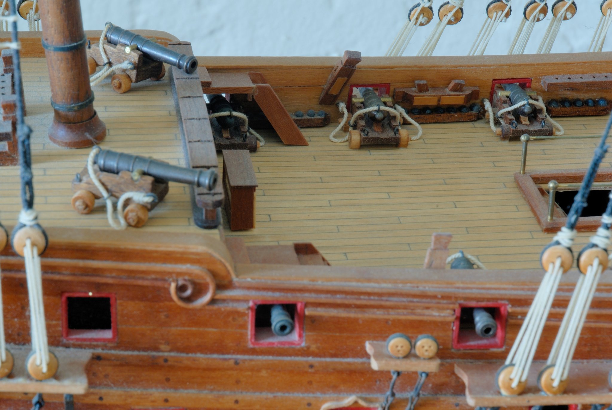
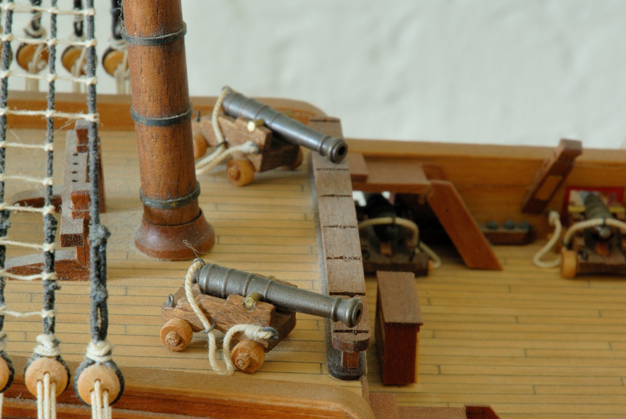
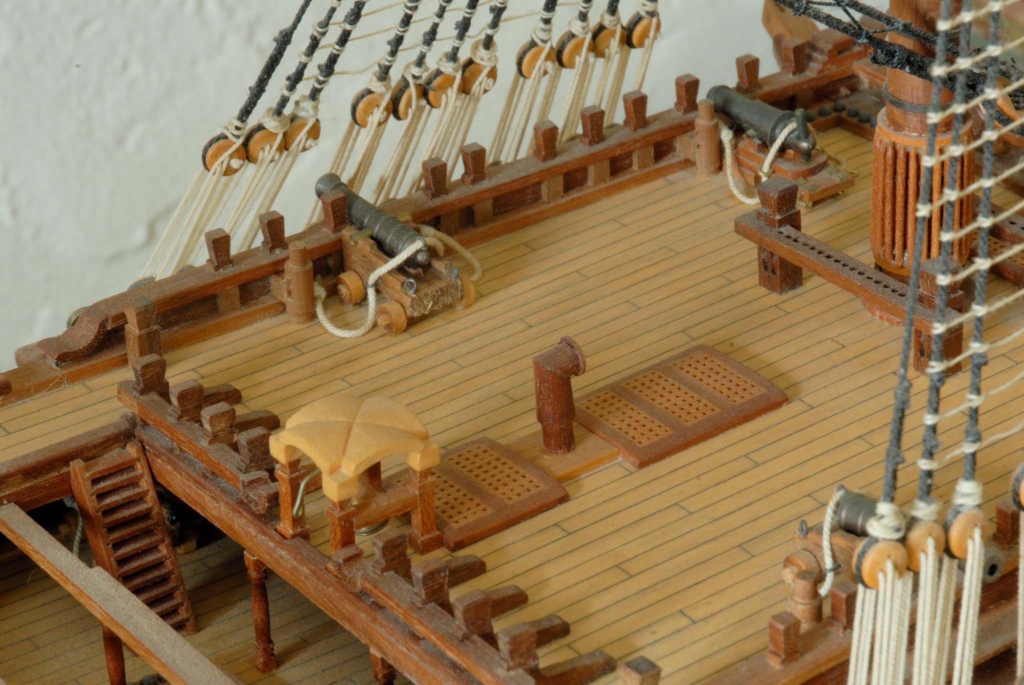
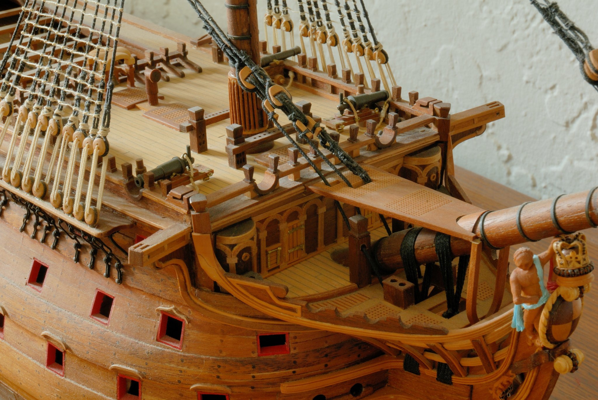
:-) I forgot to mention that my Vic model I was building ~ >10 yrs ago and never to this day finished it (some masting and rigging remains...). That was an old Corel kit which I substantially bashed, added my own wood, rigging line, ornamentation and cloth for sails, and so forth... Among the items missing in the kit were four top deck cannons. Rather than ordering them directly from Corel, I decided to make them myself. And - apologies - now that I checked the (very dusty - sorry!) model again, I see I turned them not from wood, but from brass! I remember I used one of the kit cannons for its overall shape and filed a brass template of its profile. I mounted this template in the duplicator and CAREFULLY and DELICATELY following its shape, I turned them. Each one came out tiny bit different than the others (especially the reinforcing rings on the barrel) , but after cleaning them with files and polishing them, they turned out acceptable. Also, it is advisable to grind both ends of duplicator's bits to form a steeper cone, more pointy, the tip should be narrower and almost as sharp as the exacto knife? That way you can turn more intricate details. Long time after, and now, I am scratchbuilding 1:48 scale French 74 gun ship (after Boudriot) and for this one, I used all brass turned cannons, using a CAD/CAM method. This is a far better way than using a duplicator - all cannons turned out beautifully, all are identical!!! But, if you are unable to turn them on a computer, I think that using a duplicator is a worthwhile try - see if it works for you. Here are 5 pics of what I was talking about - first two show those 4 missing in the kit guns mounted on the quarterdeck, I made. Actually, I made 6 of them - two spare ones you can see placed loosely on the poopdeck. The rest of the pics show other guns placed on the top deck and especially on the forecastle - those came in the kit.


-
Duplicates for Sherline Lathe
Dziadeczek replied to John Rose's topic in Modeling tools and Workshop Equipment
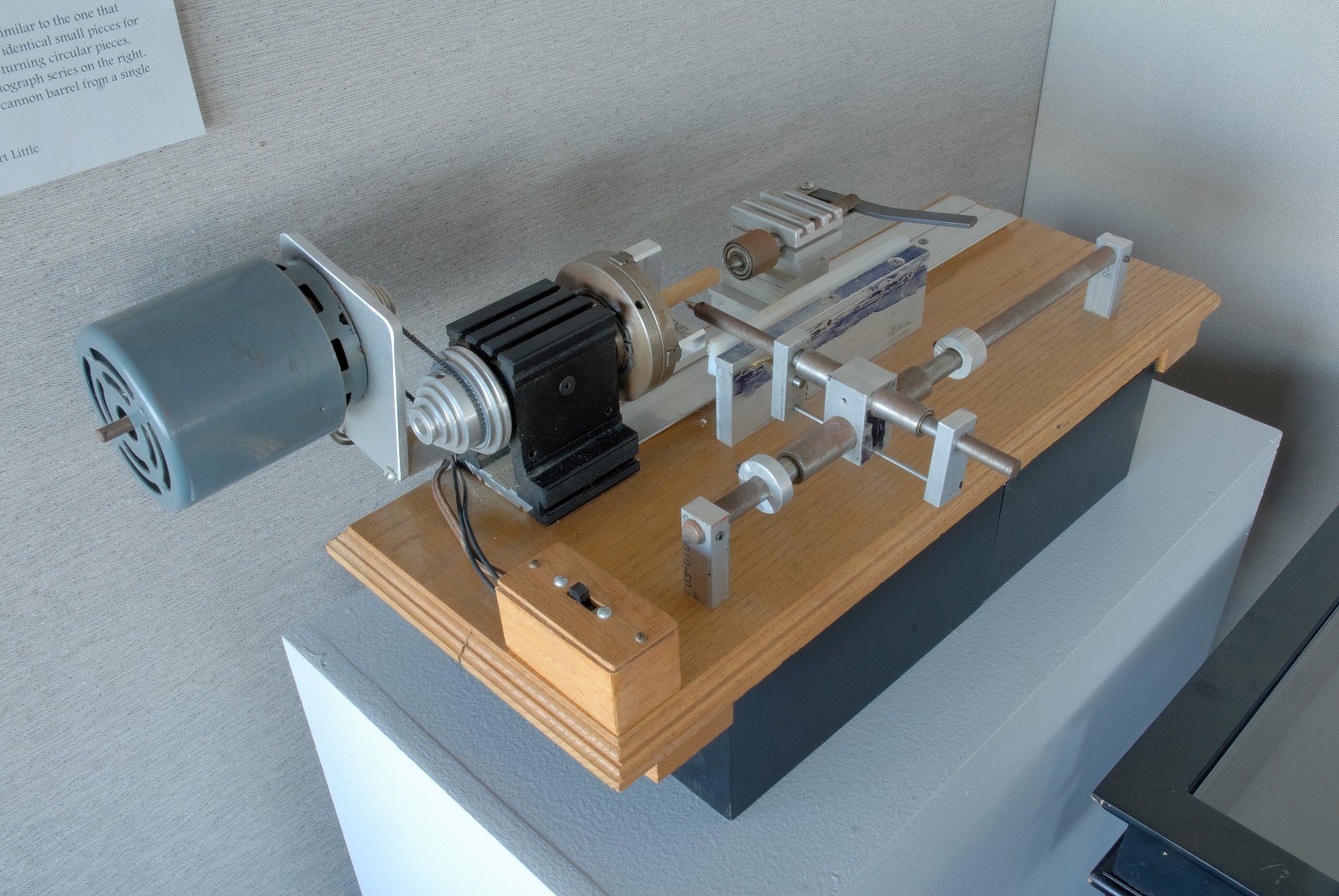
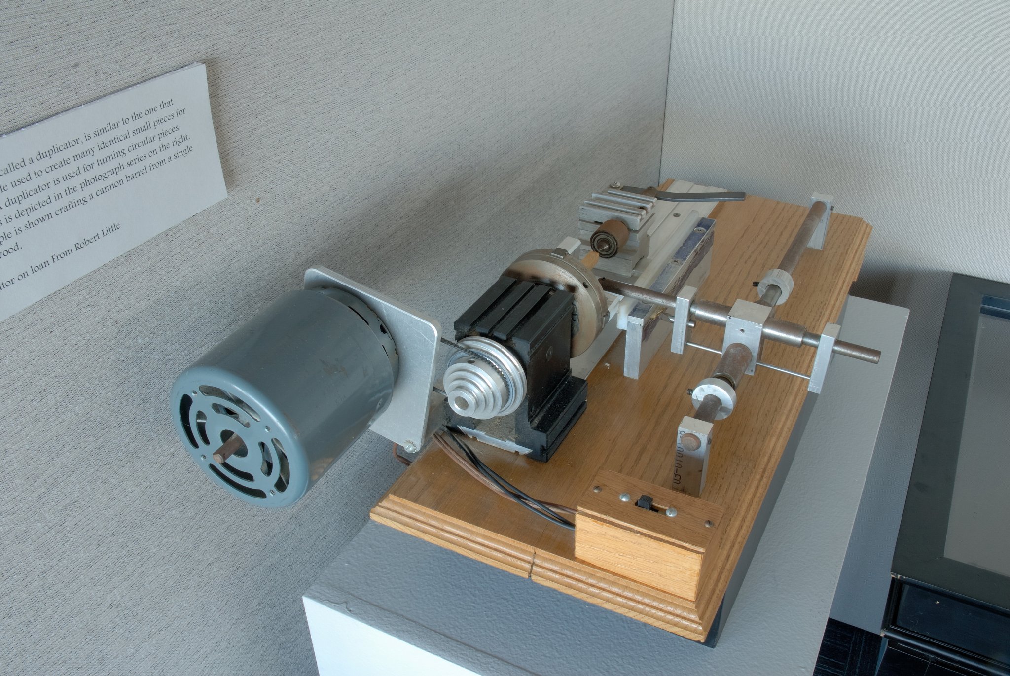
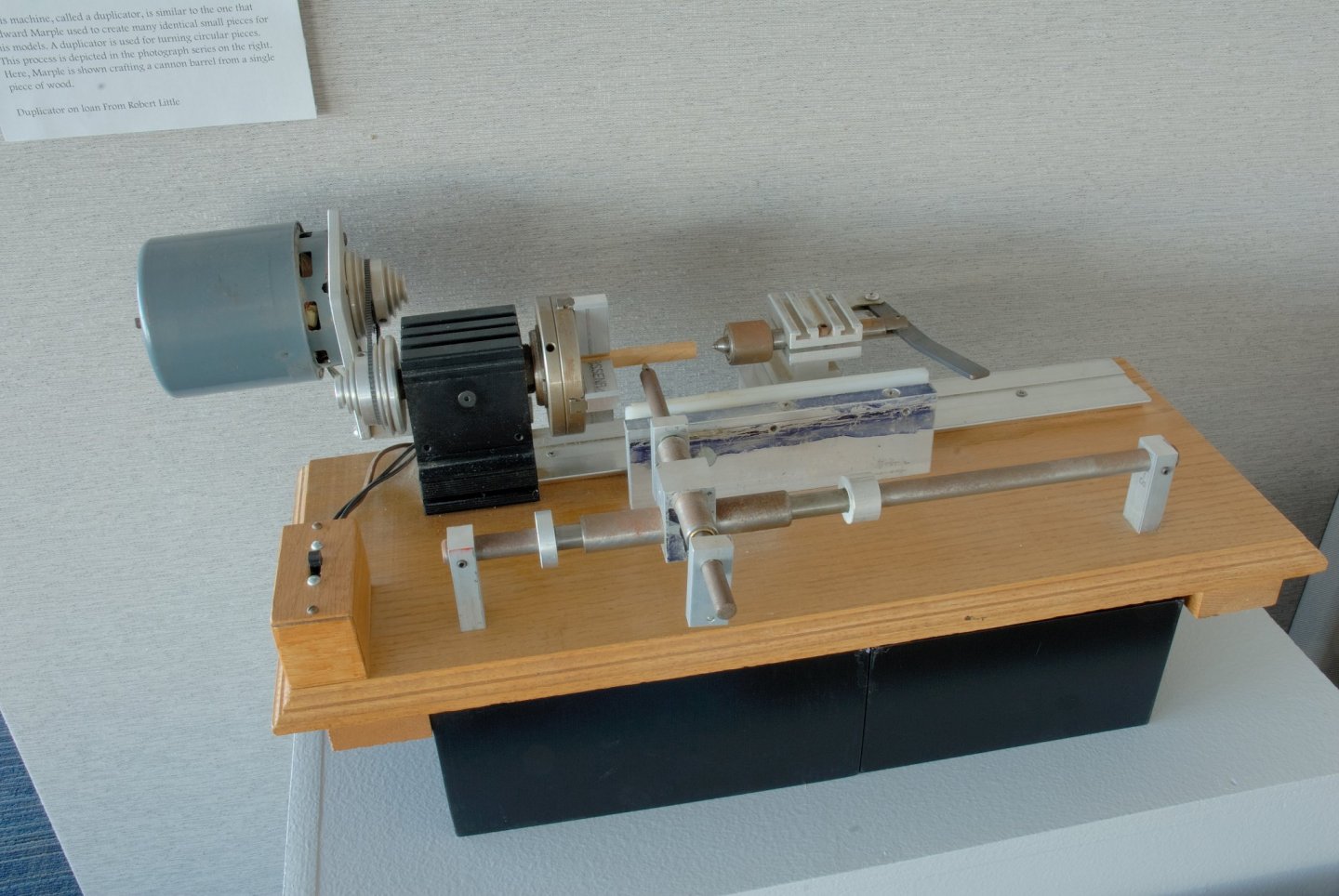
I have this duplicator and I also have a Sherline lathe. Have done some work (wooden cannon barrels for my Victory 1:98) with this setup - works reasonably well. Still, you have to finish your turnings with miniature files and fine steel wool for details. (Nothing beats CAD/CAM turning in brass, though!) The article mentioned was in nr. 105 of Model Shipwright ( I believe that in the Ships in Scale as well) and the Unimat lathe was used there. For a Sherline lathe you'd have to slightly adopt this duplicator, fashion legs for the base to bring the entire unit to an appropriate level. But it can be done fairly easily. If you want this article (4 pages), I have it digitalised and can send it to you via the email for your reference. PS: Similar setup can be seen in the Channel Islands Maritime Museum in Oxnard, S. California. This is a duplicator used by Ed Marple for his models (See pics attached).

-
I found this on the Web: https://www.highlandwoodworking.com/woodworking-tips-1606jun/toolreview/sterling-roubo-curves-tool-review.html
-
Mark, Check out this thread: I wholeheartedly recommend this heat/water bending technique, especially the method presented by Mr. G. Kammerlander about 3/4 down that page - a piece of video in German, but the pics speak for themselves. Long time ago there was an article on this very topic in the "Ships in Scale" magazine, where I discovered his technique, and it still works for me. I am quite convinced that you should be able to bend your piece of walnut 90 degs, as you want it. Recently I managed (with some difficulty and patience, I must admit) to edge-bend a 2 mm thick piece of ebony (for some curved railing) with my electric plank bender (well..., converted soldering iron, but it WORKS just as well)! And we all know how difficult is to bend ebony!
-
Does it have to be African walnut? How about ordinary American variety? Or South American (a bit darker)?
-
Since nobody wrote anything so far, I will give it my three pennies. It appears to me, that the modeler used a soft wood plywood for the decking and tried to score it (with a pencil?) to mark its planks. The scoring is not very well visible, sometimes the natural grain of wood is more pronounced than that and overwhelms it. Also, there appears to be a few rather large holes in the center, between the mast holes. Because of all this and overall unevenness of the wood and its blotchy appearance, I would tend to rather replace the entire decking, using either individual strips of some hardwood (like fruitwood species, or perhaps birch or (best IMHO) beech wood, or even very lightly colored holly), with one edge blackened, and glued them tightly, running along the center axis line, next to each other ON TOP of your old deck. Or - if you don't have the possibility to cut those strips yourself, make the entire deck from a thin (1/16 to 1/32 in. birch aircraft plywood and score the run of the planks on it with a hard pencil, like 4H or so. Select the piece of plywood that has possibly the smallest, most even and regular grain. But before all of this, you will have to thoroughly scrape off all your polyurethane from the old deck, since the wood glue will not adhere to it. The best way to do it is with a piece of sharp edge of a broken glass (ducktape the rest of glass to avoid hurting yourself!) or an industrial razorblade, or even a sharp edge of a chisel. Then make a precise cardboard template of the new deck making sure that it fits tightly around the bulkheads extensions of your bulwarks and other structures on top of the old deck. Only then draw its shape with a pencil on the plywood and cut it carefully with a sharp exacto knife. Replace the deck, gluying it on top of the old deck. The small height difference afterwards should not present a big problem, I think. Next step is to paint your new deck wit a liquid called WOOD CONDITIONER by Minwax (obtained in places like Home Depot, or such) - this will prepare the wood for even staining without blotches and/or oiling it with Danish oil. When the deck is still wet from this wood conditioner, stain it (if you want it) and/or oil. I'd personally rather not stain it at all, just oil it. No other glossy laquers, polyurethane, or such!
-
Years ago I bought an Iwata + their compressor, and they are still going strong! Don't regret buying them.
-
You mean like this one? https://www.dailybreeze.com/2017/12/08/out-with-the-old-ports-o-call-transition-sparks-angst-and-confusion-on-eve-of-demolition/
-
safety neting construction
Dziadeczek replied to Thomas Staley's topic in Masting, rigging and sails
But if you want to torment yourself, try this: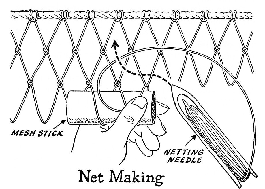
-
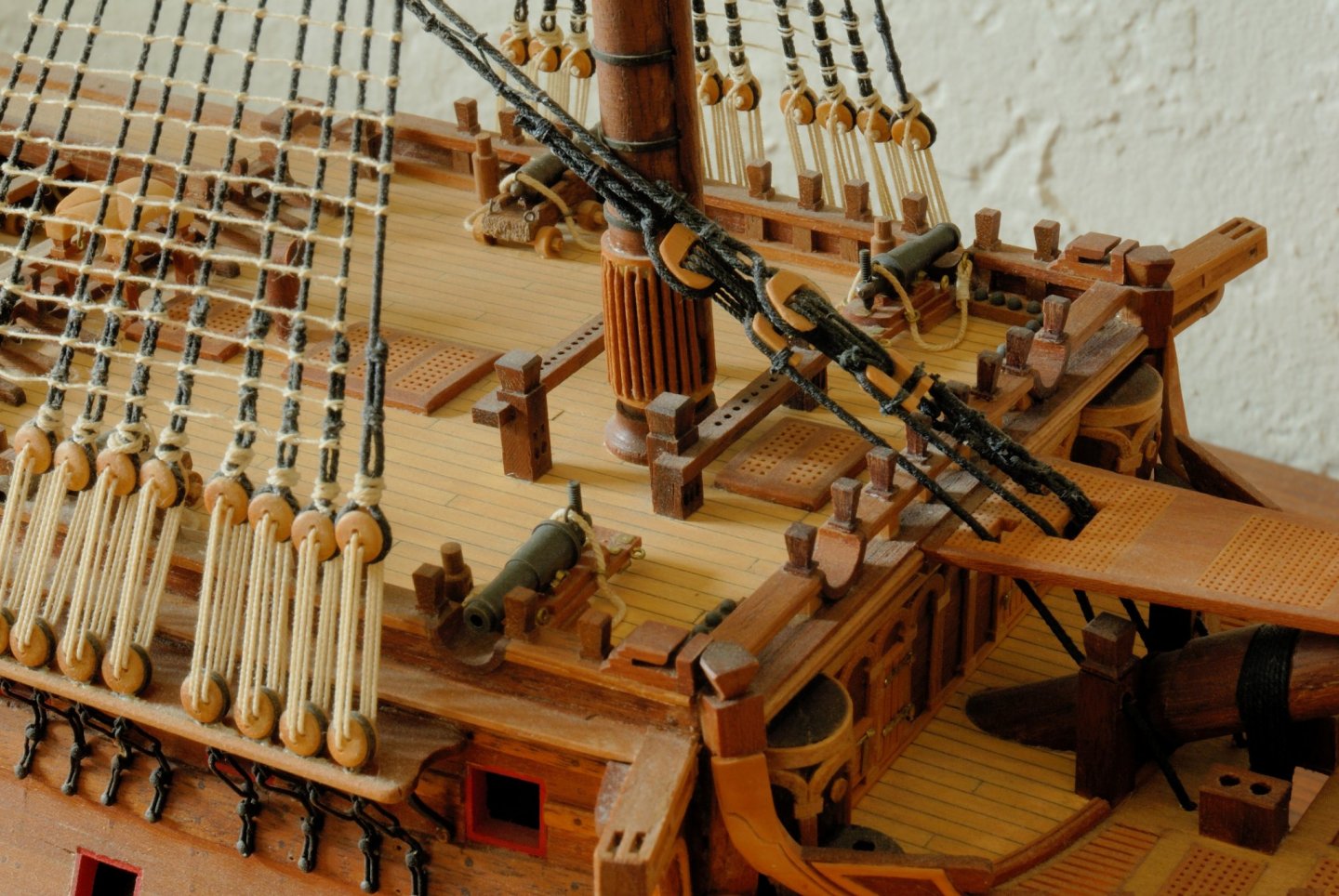
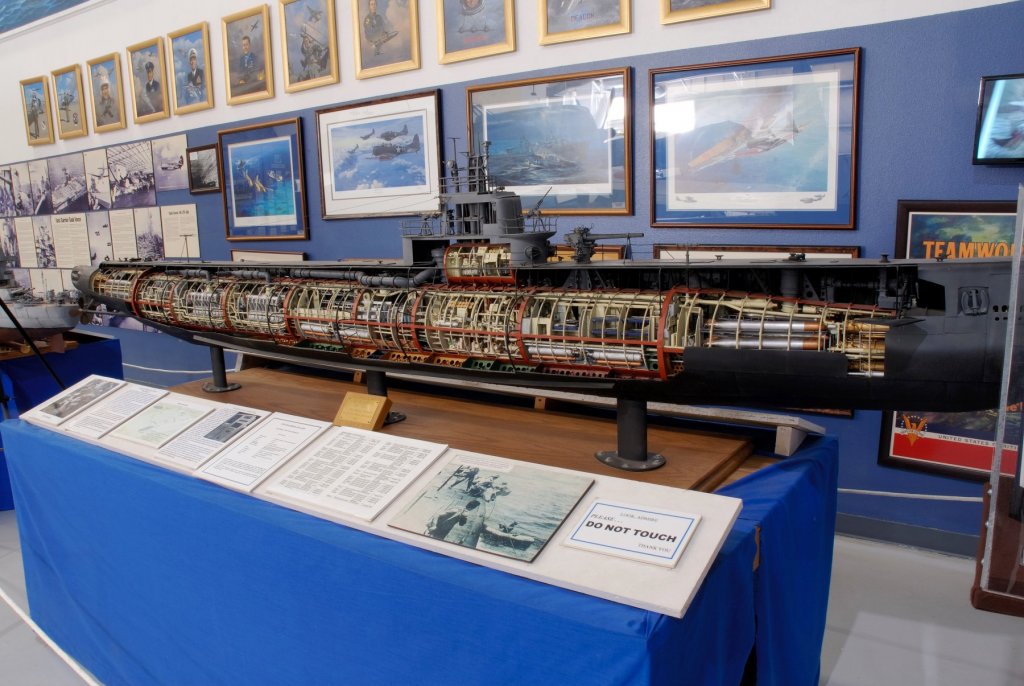
Fantastic model! I admire the craftmanship of the modeler, but this is also very educational, of how these vessels worked! It reminds me of a large scale model of the WW2 US sub, the USS Rasher, which is housed in the Palm Springs Air Museum in Southern California. One could stand there and gape for hours!
- 760 replies
-
- 13
-
-
Lloyd Warner only drilled one pair of holes in his double blocks, because the other pair (of holes) will not be visible (or be nearly invisible) under the rope passed through the block anyway. I am sure, you know that inside the slot cut through the block, there is a sheave upon which the rope rolls. In order for the rope to roll, it has to be passed ON top of the sheave (pulley) and not under it. Here is a couple of pics showing it in detail. Hope it helps. Regards, Thomas