HOLIDAY DONATION DRIVE - SUPPORT MSW - DO YOUR PART TO KEEP THIS GREAT FORUM GOING! (Only 20 donations so far - C'mon guys!)
×


Dziadeczek
-
Posts
645 -
Joined
-
Last visited
Content Type
Profiles
Forums
Gallery
Events
Everything posted by Dziadeczek
-
Should be CA. Sorry...
-
I don't know what size of these eyelets you need? In any case, I once found a plastic box of tiny eyelets (I think they were 1/8 in.) on Amazon for dirt cheap (their shafts were threaded though, and not smooth). But, if you have a pin vise, get a short length (about an inch) of wire, the thickness of which is the same as the size of your eye on the eyelets you need. Shape its end into something similar on the pic you attached above (but do not close the hook completely!). Take a similar length of the wire for your eyelets and bend it into "U". Clamp both ends in a vise and catch the "U" with your hook mounted in the pin vise. Twist the pin vise in your hands until the wire will clamp tightly around the hook. Cut off ends for desired lengths. Release the eyelet from the hook. If you want to have smooth shaft, cover the twists with a melted solder, otherwise left alone, they will act like a thread and pushed into a hole and CD glued, will sit there tightly.
-
If you are referring to tiny wire rings, you can make them by wrapping a piece of wire around a shaft of a drill bit (of suitable thickness) fastened in a vise, to look like a spring. Than stretch this spring a bit and cut off individual rings. If you want to, you can solder the ends of each ring together with a tiny soldering iron. If you are referring to small thimbles, you can make them from a piece of small brass tubing, by cutting off short lengths on a small table saw (I have the PREAC) and than gently hammer each end out with a nail that has its end shaped (filed) like a funnel.
-

kit review 1:120 USS Susquehanna - WoodyJOE
Dziadeczek replied to James H's topic in REVIEWS: Model kits
Hi Erik, Where do you get your Woody Joe kits from? Ages ago I built a nice little model of a Japanese brigantine "Osyoru Maru" from the now defunct Japanese company IMAI (which was subsequently bought by Woody Joe). I remember, this was a nice little kit, good quality materials and pictorial instructions easily understood (I don't speak Japanese). Although, I remember, I replaced kit's wood with my own cherry, pear and maple... So, if Woody Joe makes equally good kits, you won't be disappointed with your Cutty Sark. Where exactly do you live in LA? I live in Glendale, in the San Fernando Valley, between Pasadena and Burbank. I wish we could meet next year in the planned (so far) Nautical Research Guild conference, provided this Covid19 paranoia finally goes away... I am keeping my fingers crossed! We could talk about shipmodeling until the proverbial cows come home, he he... 😄 What are you currently building? I am in the middle of the rigging on my Frenchie in 1: 48 (after mr. Boudriot's 4 volumes on the 74 gun ship). Painstaking task! Regards, Thomas -
Papegojan 1627 by mati - FINISHED - 1/48
Dziadeczek replied to mati's topic in - Build logs for subjects built 1501 - 1750
Mati, Make yourself a few rigging tools, like those shown - to make this task easier. Otherwise, your model looks PERFECT! Congrats!!!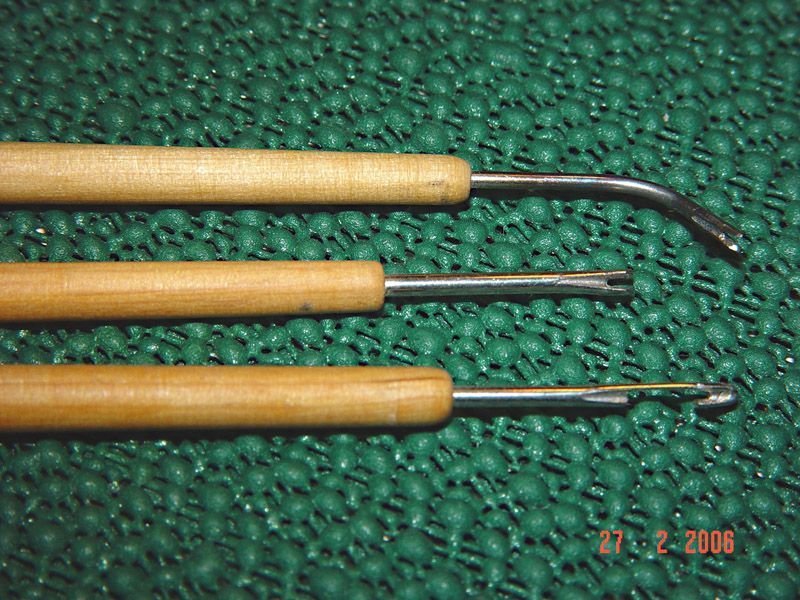
-
Papegojan 1627 by mati - FINISHED - 1/48
Dziadeczek replied to mati's topic in - Build logs for subjects built 1501 - 1750
Mati, Hung your coils onto the pins, like it is shown in this video. -
Please open up the link below and subsequently go into the link in my entry there, to read my thoughts on plastic deadeyes and blocks from Billings. For the reason I mentioned, I would replace all plastic fittings into wooden ones and bend them properly (wrap the running ends of shrouds AROUND each deadeye), because the little eyelet on each deadeye will break away in time, under the tension from the rope. Plastic is brittle!
-
Thank you, Moderator.
-
Out of this world! May I ask you, how did you carve (?) this lettering "DE 36"? Thomas
-
Also I found this one: www.jans-sajt.se/contents/Navigation/Galleries/MyModels_Heller_Le_Soleil_Royal_100.htm
-
Frolic style ropewalk plans
Dziadeczek replied to Chuck's topic in Rope Making/Ropewalks's Ropewalk Plans/Downloads
For the modeling purposes the looper is not necessary, just the whirls will suffice to twist ropes. -
Hi, I am not an expert on your "La Creole", so I cannot help you to answer your question, but currently I am having similar problems with my 74 gun ship I am building, following Boudriot's 4 volumes. I noticed that in his books he sometimes says one thing, and elsewhere he contradicts himself. For example, he says that the running end of the fore topmast preventer stay is tied to a deadeye and the second deadeye is made fast to a jackstaff standard on the bowsprit, with a lanyard in between. But on his plans he clearly shows two blocks instead! Go figure! I think that either you will have to faithfully follow Boudriot, or use your own best judgement and perhaps make your stay, say 25 mm thick - something in between 40 mm and 15 mm, (which is on item nr. 26 on your plan). Thomas PS: I always hugely admire your build - it is an inspiration for me with my own build, but I cannot come to your quality nearly enough! 😬
-
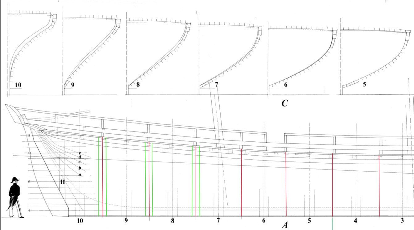
Hi Tony, The way I did it, I took a sheet of a grid paper (with 1 mm increments) big enough for the entire frame, and drew two lines on it; one horizontal line near the bottom of the sheet and 2nd line vertical through the middle. Then I drew several horizontal lines, parallel to that first horizontal line, but at various heights, the distances between being exact with the waterlines on your sheer plan. These lines will represent the same waterlines on your body plan (sections' plan). Then take a compass and from your half breadth plan take distances between the keel and each waterline for each frame and transpose them onto your body plan at the corresponding waterline, and repeat this for all waterlines. Finally connect all points into a curve representing the half profile of your frame. In order to obtain a full profile, bend the sheet at the vertical line, place it on a light box and with a pencil trace the opposite profile. Or, when you mark the above mentioned points on your body plan, mark them symmetrically on both sides of this vertical center line. This is done manually, folks with computer programs can do it much faster, but I did not own such a program at that time. This curved line only represent a mid section in between both parts of this "sandwich" that makes a frame. You will have to draw a few more lines like that in order to have a full shape of a frame. See, each frame hypothetically cut horizontally at a given level has a rectangular shape - for the mid frames , but this shape changes as you go towards the bow and the stern of the hull - they become progressively parallelograms due to the hull's oblique shape. You have to determine these shapes - for each frame and each waterline level. At the end you will have four curves - for each waterline, one is for a forward outer profile of a given frame, second is for a forward inner profile, third is for a rear outer and fourth is for a rear inner profile, so the entire process is quite laborious and time consuming, done manually. English is my second language, thus perhaps my explanations are not adequate enough, but I found a pretty good article on the internet, by Gene Bodnar, explaining everything in detail. Here is the link: SCRATCH BUILDING A MODEL SHIP (modelshipworldforum.com) Jean Boudriot is generally very good and precise in his plans and drawings, but as always, there is no guarantee and mistakes happen. I suggest you make your own body plan (transverse sections) for all frames, making sure about their proper heights at the level of the deck and/or rail. Regards, Thomas
-
On the drawing you provided, Boudriot indicates spacings among the frames - the middle spots shown as short vertical lines between frames 1-10. From these points I would draw vertical lines up to the deck (in red on my copy) and from those, I would draw two (green) lines parallel to the red ones showing the "thickness" of your missing frames, and thus placing the "rest" of the frames on the plan. La Jacinte was not a big, heavy, Navy ship having many tightly spaced frames, like the ships-of-the-war, so I would assume that in between station frames (1-10) there was another, one ordinary frame (unless someone has a better info). Do the same on your half breadth plan (vertical view of the hull). On the intersections of these lines with your waterlines (on your half breadth plan), you will have points, delineating shapes of your missing frames.
-
Ages ago I had to hand draw missing frames from Boudriot's plans for my 74. He only drew the so called station frames, but "for the clarity of the drawings" omitted the others. It took me considerable time to do it (of course, like mustard after dinner, later on Ancre issued addendum to the 4 volumes with ALL frames included, lucky me... 😬 ). I remember I used waterlines from a half breadth plan as well as a body plan to draw missing profiles. It worked...
-
Poor piano...
-
Treenail holes
Dziadeczek replied to Don Case's topic in Building, Framing, Planking and plating a ships hull and deck
Why don't you impress into the wood tiny circles imitating treenails, with a sharp edge of a medical needle of appropriate size, or any other metal tube? They look perfect after slight push and twist of such needle into the wood and one coat of Danish oil. (besides, that way it's lots less work...) -
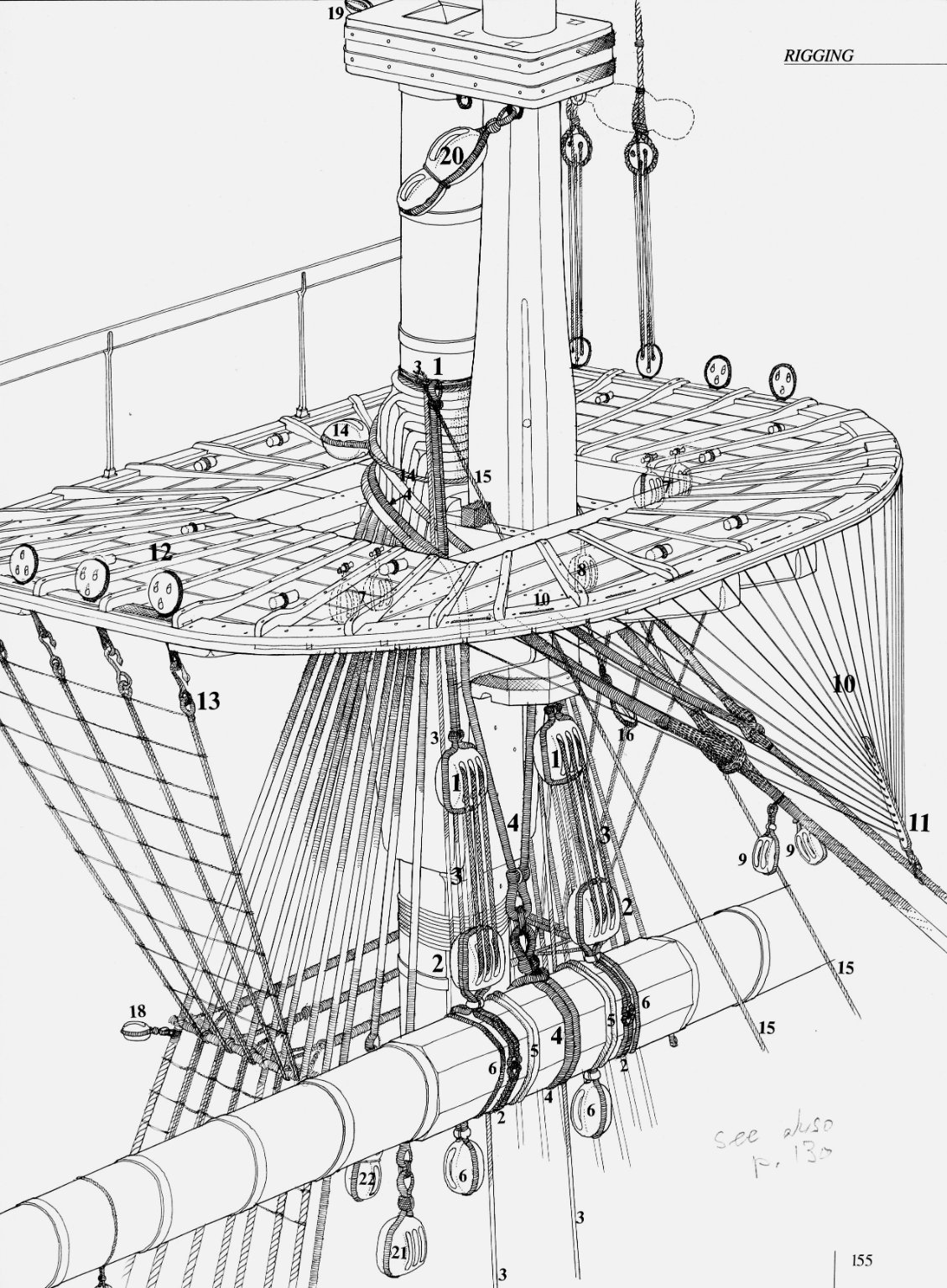
I am building a French 74 guns ship 1:48 from J. Boudriot, and these items (# 10, 11) will be on the menu in the near future...

-
Vanda-Lay treenail maker - Building, Framing, Planking and plating a ships hull and deck - Model Ship World™ I have all three cutters they used to make. The smallest one is very difficult to use, the hardwood tends to break during cutting. The other two work OK, if you carefully use hardwood, like cherry, maple, pear, and the best of all - boxwood. I successfully made lots of treenails, also used an extension tube to cut them longer. But, if you want to make your treenails from bamboo, it is better to use a drawplate. Bamboo has long and strong fibres that tolerate firm pulling. If however you want to make your treenails from hardwoods, the treenail maker works better - because you're pushing the wood, not pulling (provided that the cutter size is correct for your scale).
-
If your deadeyes look similar to those I had to deal with (building my Norske Love from Billings), throw them away and replace them with wooden ones. Check the link here: Norske Love by Mike Reader - Billing Boats - 1/75 scale - - Kit build logs for subjects built from 1751 - 1800 - Model Ship World™ If however you bent them properly (wire around each deadeye and into a chain plate), they should be strong enough and you can use them. (I cannot see yours close enough on your photo). Thomas
-
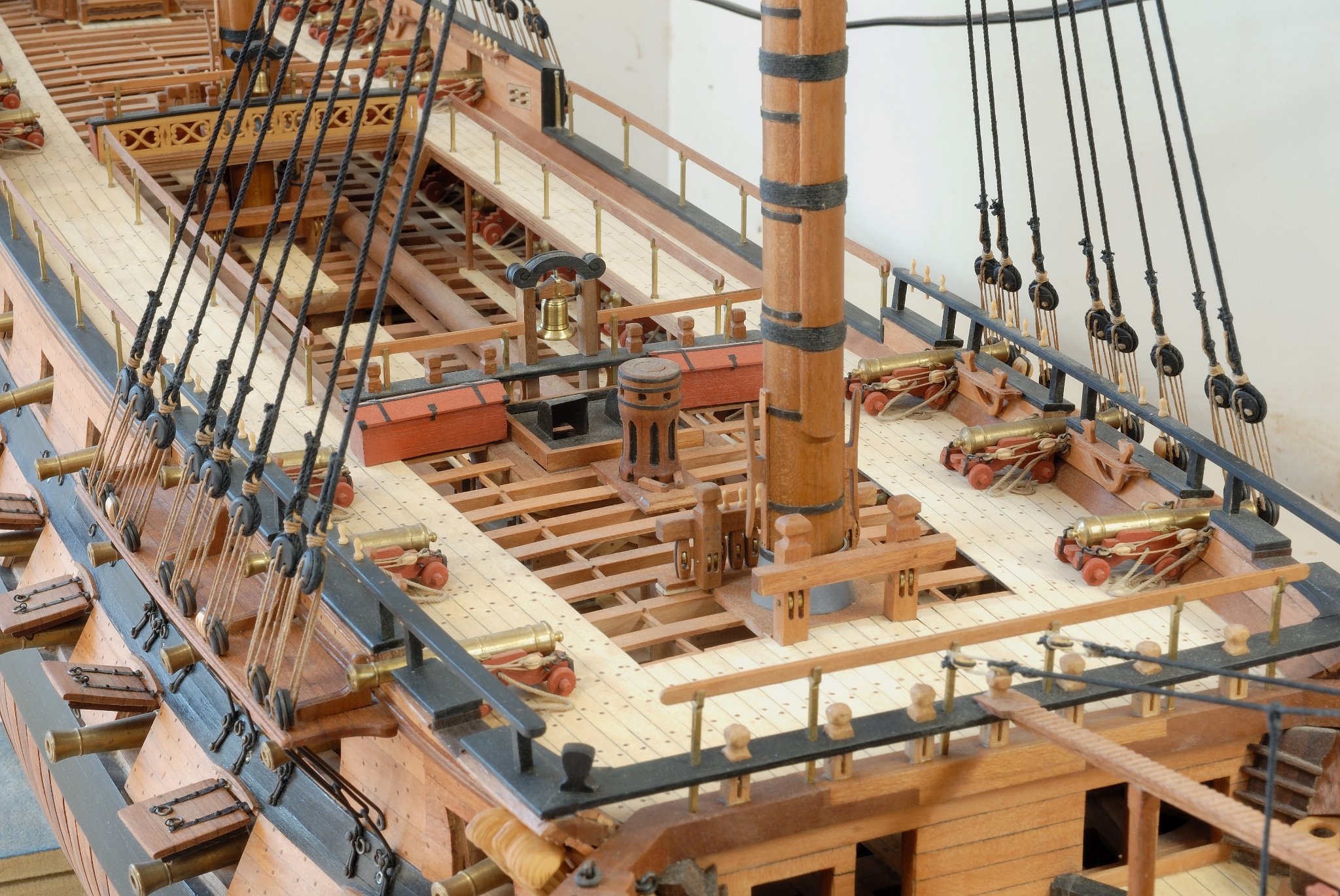
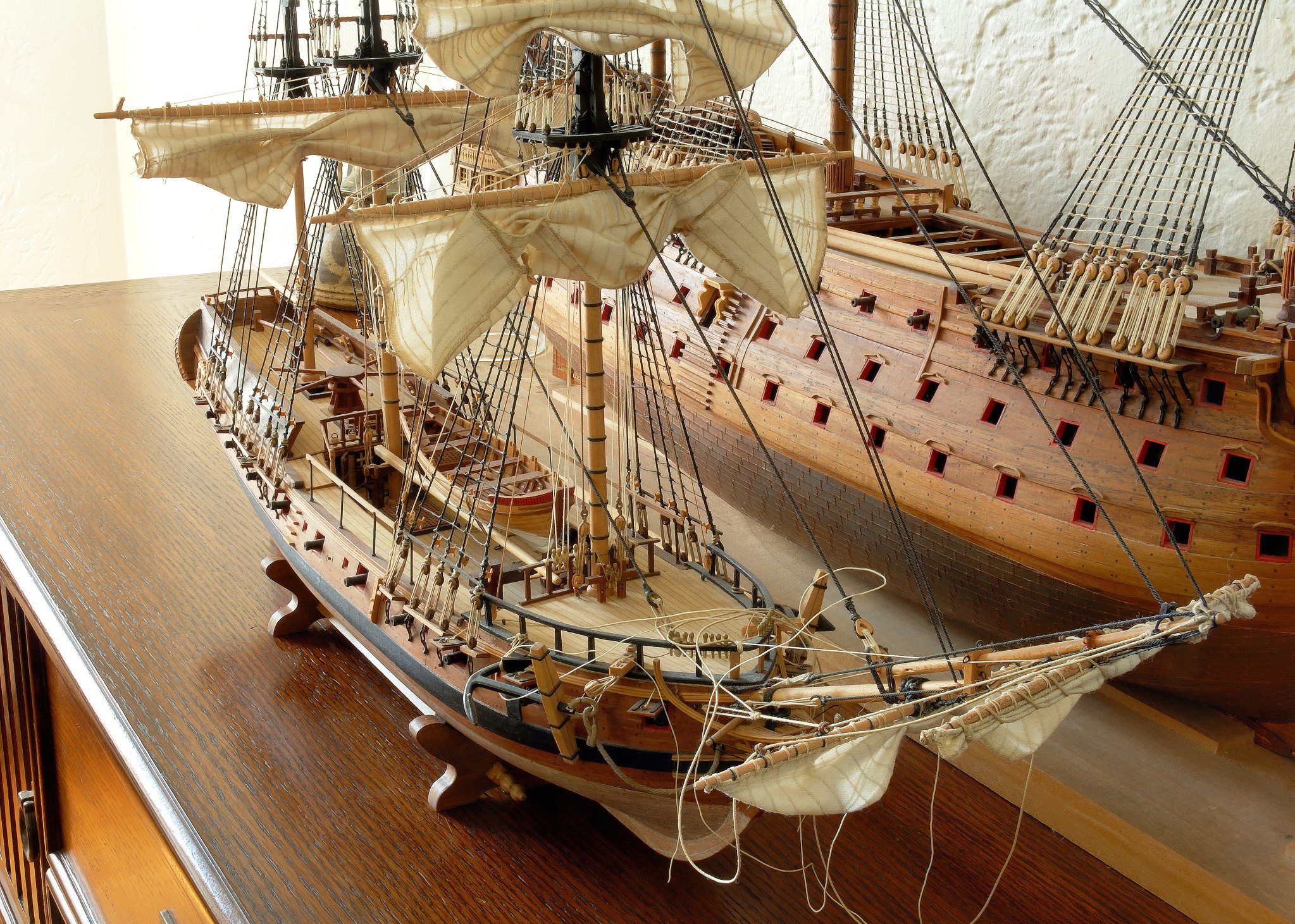
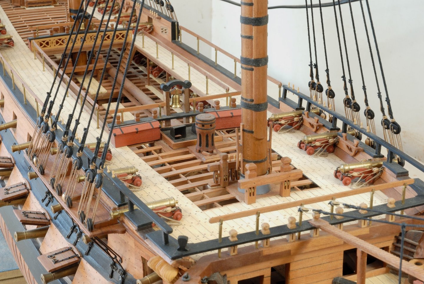
Everyone has his own tricks up his/her sleeves on how to photograph models, but over the years I noticed that it actually is quite simple and doesn't require any expensive equipment or a studio setup. All you'll need is a camera (preferably a digital SLR type, so you can exactly see what you are photographing, which in macrophotography is more important than in, for instance, a landscape photography, because here we are dealing with a parallax error). Also the second piece of equipment you need is a tripod. And, off course, a model! 😁 You can use a standard lens, if it'll allow you to come and focus close enough to the subject, say min. about a foot, or so. Anything closer - you'll need a macro lens (might be expensive!) or a special (cheaper) macro ring which you'll mount between your standard lens and a camera body. This ring will allow you to focus much closer than the lens alone, a few inches or even closer, depending on the ring. When I photograph models, I NEVER use any artificial lighting, e.g. a flash or any studio lamps. This type of lighting will give you sharp contrasts and ugly shadows, which might obscure details of the model. I photograph preferably on the outside and only when the day is cloudy or overcast. Never in the full sun! If I want to use a neutral background, I place the model in front of a sheet of lightly colored (blue or green) paper, but if the model is too big, I use natural background. On the inside, I use ambient light only, sufficiently diffused. I place the camera on the tripod and set it on APERTURE PRIORITY and then select the smallest possible in my camera opening, say F. stop 22. The smaller the opening (bigger number), the deeper the depth of field will be, in other words, sharpness of all the planes. Macrophotography has notoriously shallow depth of field and you want to extend it maximally. This small aperture will allow equally small amount of light through the lens and the picture will turn out too dark. So, you want to extend the time of exposure accordingly to compensate for it. In the setting Aperture Priority, the camera will do it for you automatically. Typically, the time of exposure will be way too long (for ISO 100) to keep the camera steady in the hands and result in a blurred pic, hence the need for a tripod. Also, set the camera on SELFTIMER, say about 5 seconds delay, in order to avoid shaking the camera during the pressing of the shutter button. If your camera doesn't have a selftimer, use a cable release. Next thing is a composition. Before you take the pic, you should briefly think what exactly you want to show in it and compose the pic. Don't be afraid to frame as much as possible the details you want to show. Remember to focus first on the detail which is located about 1/3rd closer to the camera - that way everything closer to this distance as well as further away will still be in focus. In the first pic I attached, I focused on the capstan. The camera sometimes will select automatically another detail not necessarily at that distance, so in order to convince it, PRESS THE SHUTTER HALF WAY while focusing on that detail (in the middle of the frame) and KEEPING IT HALF DEPRESSED simultaneously recompose your pic and finally press the shutter all the way to take the pic. I always photograph with the setting RAW. The so called, post production tweaking is as important as the actual picture taking - with RAW you can manipulate sharpness, contrast, brightness, color saturation and many other parameters, which JPEGs don't allow you. Only after all manipulations, convert it into a final JPEG. If the depth of field (focus) doesn't satisfy you with this technique, try the Focus Stacking technique. Use a tripod here too, take at least 10 or 15 pictures of the subject (with Aperture Priority again), don't move the camera on the tripod, but with each picture manually change a bit its focus, focusing every time slightly further away. Get the entire operation covered with pics of varying focus. On the Photoshop or other similar software, place (stack) all your pictures, one on top of the other, and electronically merge them together. In the end, EVERYTHING will be in perfect focus. Save this final pic. The second attachment shows one of my Focus Stacking experiments with my model of the MS Rattlesnake (not just finished there). Oh, I almost forgot. When you photograph models in their glass cases, say in a museum, to reduce those ugly light reflexions, use a polarizing filter. Depending on how good it is, these glares might get significantly reduced or even eliminated. Off course, there is also a way of panoramas picture taking, and/or a 3D pictures (yes, for macro objects too). But, this is another matter...

-
Why do you say it won't blacken the solder? It will. I assume you are going to work with the Birchwood Casey solution for copper/brass. Before blackening, carefully clean the metal with 0000 steel wool, wearing latex gloves and paint your masthead with shellac or clear matte varnish to prevent the blackening agent later on accidently spilling onto the wood and staining it blue. (For this reason I blackened my bands outside the model and mounted them after). Carefully "paint" your mast band with the Birchwood Casey solution, using a tiny brush dipped in it. Before the next tip, dry the brush by rubbing it against a paper towel or a paper napkin not to 'contaminate' the solution in the bottle. (The solution on the brush tip quickly becomes blue in contact with metal). After about ~15 seconds wipe the band dry and immerse it in clean water and finally dry it. If the blackening process is not total (areas of metal in between blackened ones) touch them up again wit the brush and after about 10 seconds, clean again. (I noticed that sometimes Birchwood Casey will not completely blacken the soldered spots as nicely as it works on the brass/copper - in those places I used a droplet of a blackening agent that the folks from the stained glass hobby use - Black Patina, for some reason it worked better for the soldered places)...
-
Hi again, I just noticed that in the title it says "SCRATCH"! Wow, double congrats ! Excellent effort and result! Thomas