Dziadeczek
-
Posts
644 -
Joined
-
Last visited
Content Type
Profiles
Forums
Gallery
Events
Everything posted by Dziadeczek
-

Photo Etching - do it yourself
Dziadeczek replied to Dziadeczek's topic in Metal Work, Soldering and Metal Fittings
Many thanks for the extremely useful info I got from you all, since my last entry! Things are slowly clearing up for me, thanks to you! Dr PR - I printed your reply and will use it for future references. Ryland - this link is exactly what I've been looking for! I will try to contact Gene Berger and ask him if he could possibly etch these details for me (for a fee, of course). But, as I said, I will first give it a try by myself, if I manage to gather all chemicals and other necessary paraphernalia. I too would prefer to etch smaller plates, but unfortunately I have this one long piece of 22 cm (8,5 in.) that will have to be etched whole. Other pieces are smaller, about 2, 5 in. so perhaps I should try to do them first as a learning experience, before etching that long one, I think? In any case, thanks again! Regards, Thomas -
Photo Etching - do it yourself
Dziadeczek replied to Dziadeczek's topic in Metal Work, Soldering and Metal Fittings
Many thanks to you all for good advice! I too was thinking about getting this Micro Mark kit just for learning expernience - like you said, Mark. I may go this way later on. As far as the video tutorials, and the books, I already searched this options (and learnt a bit, thank you very much). The book mentioned by grsjax doesn't have very good opinions, is supposedly a bit dated and doesn't deal a lot with the actual etching process, so I might skip it after all. But thanks anyway! I too agree that I should start with smaller pieces - easier to etch and manage. However the longest piece I have to etch, is about 22 cm [8.75 in.] in length and I'd rather not etch it in sections and solder the pieces together later on, since I don't think it would look perfect. So I think I have to etch it whole. See the attachment (this drawing I prepared in Photoshop with the resolution of 600 dpi, so I think it should be fine enough. But I am still tweaking it). Oh, by the way, the light box I made, has both sides equipped with UV light strips (the bottom and the cover), so I can expose both sides of my plate at the same time. What do you think about it? Would it work? Yes, I know that I have to place the light sensitive transparency the ink side down, towards the brass plate, - somewhere in those tutorials it was emphasized. I intend to copy the drawings with a good quality laser printer (professional quality machine) onto dedicated laser printer transparencies (and make mirror images of them for two sided exposures) , rather than using regular printer and cheap transparencies. Someone said it makes a big difference in the quality of prints. Later on I will let you know how my experiments went. Keep your fingers crossed, please! Regards to all, Thomas PS: Does anyone know the US source of Positiv 20 in a spray can? (I couldn't find it anywhere within the US). Or should I rather use a photoresist foil? Which one is better?
-
Photo Etching - do it yourself
Dziadeczek replied to Dziadeczek's topic in Metal Work, Soldering and Metal Fittings
Bruce, The size of the plate (brass sheet 0,3 mm [0.014 in.] thick) would have to be about 24 x 14 cm [9.5 x 5.5 in.] to accomodate all parts. Since it has to be etched all the way through and the sheet is rather thick, I think that it would have to be exposed on both sides and etched a bit longer. This all is a mystery to me, but I will try to do it myself first and see if it works. If not, I will have to look for someone else who knows how to do it. At this point I am at the stage of gathering all materials and figuring out what to do. Thanks for asking! Thomas -
Photo Etching - do it yourself
Dziadeczek posted a topic in Metal Work, Soldering and Metal Fittings
Hi, I am about to embark on an entirely new technology for me - namely brass sheet photo etching and I have no clue how and where to start. Before I relegate this task to someone alse, I would like to try doing it by myself, at home, with fairly simple methods and acceptable results. I need a few intricate brass etched parts for my French 74 guns ship model, which I am building in 1: 48 scale, specifically an ornate stern balcony ballusters, quarter galleries ballusters and gunports hinges, and such... I've already built a UV lamp, have drawn some artwork and I am wondering, what's next. I have only a vague idea of how the entire process works, but don't know specifically, where I can obtain chemicals, suitable transparencies, etchants and so on, within the territory of the US (specifically Southern California). I would prefer not to order those from oversees, since these are corrosive, hazardous chemicals and I might have problems with shipment. Hence, I have a million questions to ask. Should I start with purchasing a good book, booklet, brochure, which would in simple, concise words explain everything to a beginner, and if so, which book is recommended? Are there any good tutorials? Or should I first collect necessary ingredients and start experimenting? I must unfortunately bypass the offer from Micro Mark, since their kit only permits etching very small plates and I have to etch rather bigger details. Any help in this matter will be greatly appreciated. Regards, Thomas -
This reminds me of old casein glue, which I used to homemake ages ago for building paper models. https://hubpages.com/art/woodworking-how-to-make-your-own-strong-wood-glue-from-milk It is surprisingly long lasting and strong (read about its uses in the article), cheap, easy to make and, unlike rice glue, water resistant.
-
It should be: Hi, I finished 13th row of planking. (government= rząd, który rządzi w danym kraju, row=rząd, np. drzew w lesie, żołnierzy w szeregu, itp...)
-
Vanda-Lay Industries
Dziadeczek replied to BETAQDAVE's topic in Modeling tools and Workshop Equipment
I have their treenail cutters (I see, they are no longer available - pity!) and also their thickness sander. Both gadgets are still fully functional after all these years. Very good quality products! -
Question about table saw technique
Dziadeczek replied to jdbondy's topic in Modeling tools and Workshop Equipment
Are you using Explorer? -
Wood for decking
Dziadeczek replied to JamesT1's topic in Building, Framing, Planking and plating a ships hull and deck
holly -
Table saw with a reasonable price
Dziadeczek replied to Clark's topic in Modeling tools and Workshop Equipment
Does it allow for raising and lowering, as well as tilting the blade (for angled cuts) - like the bigger Proxxon? -
Planking Clarification
Dziadeczek replied to Pond's topic in Building, Framing, Planking and plating a ships hull and deck
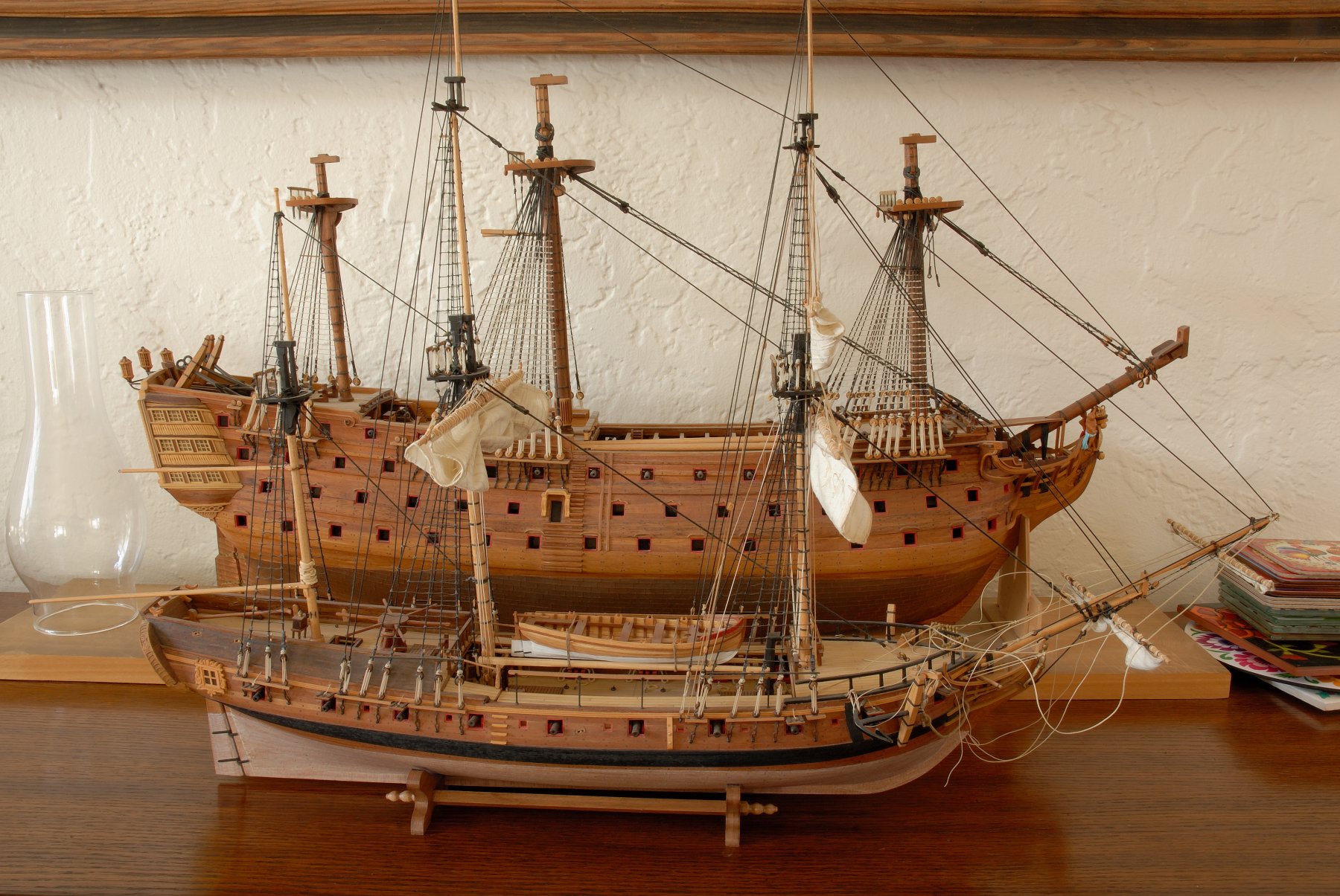
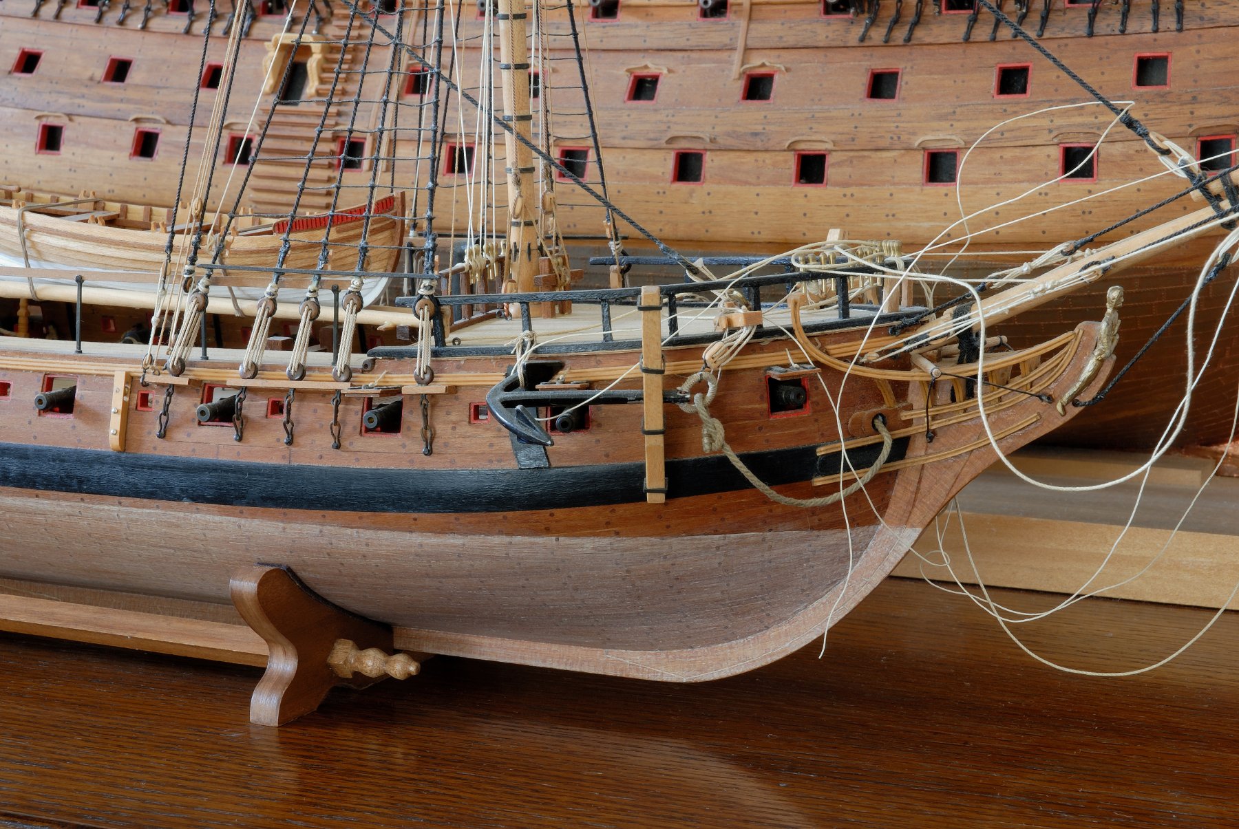
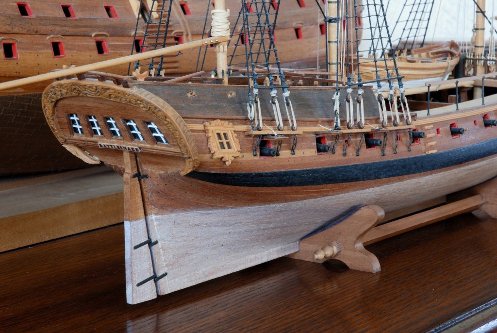
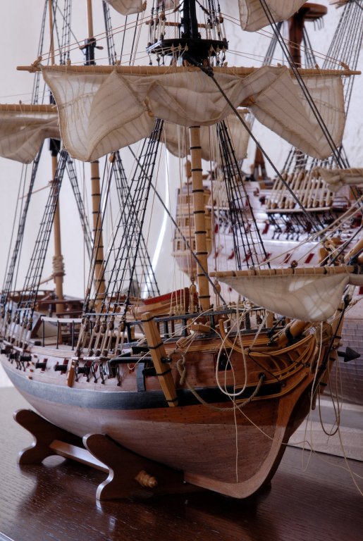
Hi Pond, A few years ago I too started on the Rattlesnake kit from Model Shipways (due to its size I wouldn't recommend it for beginners - parts are SMALL and FRAGILE and easily break during construction). To this day I still didn' manage to finish it - a few sails remain to be hunged. As you'll see in the attached photos, I also slightly bashed the kit, using my own wood (mostly cherry), etc... As you'll find out, there are many ways to succesfully plank the hull, every modeler has his favourite one. In the kit you have excellent plans and step-by-step instructions by Ben Lankford - stick to them and you should be fine. Most important thing is to properly spill (shape) the planks before mounting them. Once you've attached your wales according to the plans, divide each bulkwark with battens into a few symmetrical 'belts' - eliptoid areas from bow to stern and gradually fill them up with spilled planks. Checking symmetry on both sides is crucial. Start your planking from up (wale) towards down (keel) or opposite, whichever way you prefer. Shape (spill) a PAIR of planks (each plank for one side of your bullwark), wet them for a few minutes in lukewarm water and hot shape them with your plank bending iron, first outside of your model, frequently checking the curvature against the skeleton of your hull. I think that your steaming box is, in your case, an overkill (they were used in full size practices, but your planks are scaled down, so much smaller and thinner than the full size boards, that it s quite easy to shape them when they are just wet. The soldering (plank bending ) iron will dry them almost perfectly during the bending process, and if you glue them and pin them both to the bulkheads, one on each side, they won't warp your hull. Especially if you keep the hull in the mounting board. Also by doing so, you'll ensure that your planking is perfectly symmetrical on both sides. Repeat the above for each succesfull pair of planks, until you'll fill each belt. The way I shape the planks, is, I place a wet plank on a wooden surface (e.g. wooden painting stick from Home Depot, or such), keep it by its end with one hand. With the second hand I hold my hot iron (not too hot or you'll burn your plank) and gently place its head on the surface of the plank, rubbing it to and fro. At the same time, with the first hand I gradually raise one end of my plank, giving it a desired curvature and frequently check it against the hull. Giving it some desired twist and edge-bending is also possible. When the curvature of my plank is perfectly laying (or almost perfectly) on the bulkheads, I attach it to the hull with glue and a few pins (placed every other bulkhead or so), gently tapping ordinary seamstress' pins with a tiny hammer, into the plank and the bulkhead, untill it grabs. You don't want to hammer in the entire pin - you might damage, split the plank and/or bulkhead. Perhaps three or four gentle taps will suffice... Once the entire elliptical belt is filled, remove the batten and procede to the next belt. And so on... After the entire hull is planked, I sand it with a medium grade sandpaper and/or scrape it with a sharp edge of a broken glass or sharp edge of a metal scraper - this will remove 'fuzziness' on the wooden surface left after sanding it. Good luck! Thomas PS: I developed this technique many years ago, closely following advice from a German modeler, Gebhard Kammerlander. Some time ago there was a detailed article on this topic in the, now defunct, magazine "Ships in Scale". But to this day, as far as I know, there is also a video instruction by Gebhard himself on You Tube, on how he does it. Worth checking...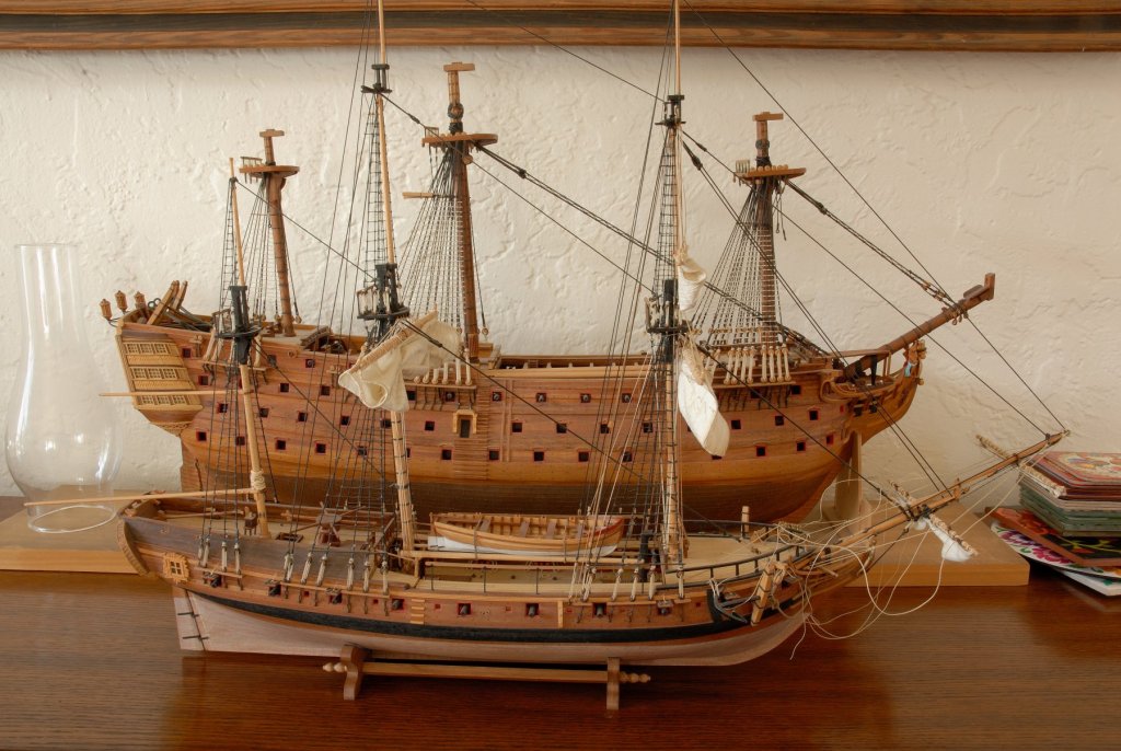

-
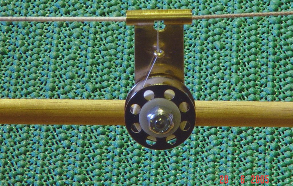
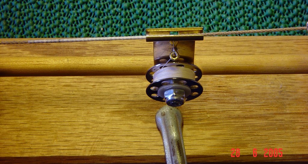
Sorry to intrude into your conversation, but the server (spool traveler - as you called it) isn't supposed to be supported in any way by this steel rod below. At least in my instance, mine hungs freely under the rope being served, suspended only by the serving thread. The gravity alone provides enough torsion and tension for serving. If the server tries to rotate around the rope, it means that there is too much tension on the thread, and you have to very slightly loosen up the screw on the bobbin so that it moves a bit easier. Perhaps the pics from Johann were taken from up and showed erroneously in perspective that the bobbin somewhat rests on the rod? Or maybe his does rest on the rod? I would like however to know, how he did the worming on that rope.
-
Holy cow, Doris! You are blinding fast, while maintaining your excellent quality standards! Fantastic!!!
- 1,035 replies
-
- 5
-

-
- royal katherine
- ship of the line
- (and 1 more)
-
I once tried to do it by hand, leading the thread into the 'grooves' of a rope stretched on a serving machine (with mixed results). Pain in the ... Maybe someone has a more mechanical and better method?
-
You have to explore the possibilities that are offered by people who are into archery. Namely, they use the so called "bow string server" which travels along the served line while serving it at the same time. Please google "bow string server" and select "images" and you'll see many potential solutions. They typically serve the line for a bow, which is a bit thicker then most of your miniature ropes for shipmodeling, so, if you want to obtain a commercially available gadget, you have to choose a possibly smaller one typically available for archery. Or, make one by yourself from parts which are typically available around your house/workshop. The solutions are endless... The beauty of such a server is that it requires no, or very little attention, while serving your lines. It hungs suspended from your rope and its weight and tension controlled by the screw (next to a spool with thread), controls how tight is your serving. (Initial setup is therefore required) . Once you start your serving process, you can literally make yourself a cup of coffee and drink it while observing the action of serving (provided that your serving machine is mechanically powered (electric DC motor) and you are serving a long enough piece of a rope). The server, while serving your rope, WILL AUTOMATICALLY MOVE ALONG THE ROPE without your intervention whatsoever. You can even install a device that will shut off the power to the motor when the serving reaches the end of the rope, so that you don't have to watch the process. Many years ago I made a simple device for serving - see attachments. It works perfectly for most of my ropes. Bigger (thicker) ropes will require a bigger server, naturally.
-
What adhesive do you use to joint parts together? I imagine, you first bake the sheet with all parts on it, and then you put them together into a chair... With what glue? A CA adhesive? Epoxy...?
- 1,035 replies
-
- 6
-
-
- royal katherine
- ship of the line
- (and 1 more)
-
Hi Doris, If I may ask you another question. How did you make your figurehead from the modeling clay? I understand completely the theory behind these flat reliefs, which you executed so perfectly (rolling thin slivers on the wax paper and shaping them with a small brush + tweezers). But when it comes to a 3D, free standing pieces, obviously you cannot place them on a paper. Did you fashion a skeleton for your horse-mounted king from a wire - an armature, before you started to build up his body from clay? Can you bake the initial body and subsequently add to it more fine details (like arms, details of clothing and armaments) and then you bake the whole thing again, or you have to make the entire figure at once and bake it in the oven? Thanks in advance for your answer.
- 1,035 replies
-
- 6
-
-
- royal katherine
- ship of the line
- (and 1 more)
-
Un-freaking-believable!!! Hats off!!! Could you tell us what book is in the pics, placed in front of your model?
- 1,035 replies
-
- 6
-
-
- royal katherine
- ship of the line
- (and 1 more)
-
cutting out the gunports
Dziadeczek replied to ronald305's topic in Modeling tools and Workshop Equipment
I use these blades for my Exacto knife, after predrilling holes in the corners of the gunports. It works. https://www.amazon.com/Zona-39-925-Replacement-Blades-5-Pack/dp/B000MDLFNQ/ref=pd_bxgy_img_3?_encoding=UTF8&pd_rd_i=B000MDLFNQ&pd_rd_r=d4c28335-f423-11e8-a9a4-91dd53fb1641&pd_rd_w=VKgNQ&pd_rd_wg=U6dmQ&pf_rd_i=desktop-dp-sims&pf_rd_m=ATVPDKIKX0DER&pf_rd_p=6725dbd6-9917-451d-beba-16af7874e407&pf_rd_r=DQ15ED6JRRFJZ9NNNZ6B&pf_rd_s=desktop-dp-sims&pf_rd_t=40701&psc=1&refRID=DQ15ED6JRRFJZ9NNNZ6B -
Frank, If you own a mini table saw, like the Proxxon FKS, Microlux or Byrnes one, or similar, you can cut these triangles freehand. First mark a pencil line diagonally across the rectangle, remove a fence from your table saw, place your rectangle on the saw's table and carefully and slowly feed it into the teeth of your saw blade, making sure that the cut follows your pencil line. I don't need to caution you to watch your fingers while cutting, do I? :- Any minor irregularities, waviness in the cut should be subsequently evened out with sanding. Hope this helps, Thomas
-
Yamaha MT-01 by Dan Vadas - CARD - FINISHED
Dziadeczek replied to Dan Vadas's topic in Non-ship/categorised builds
Awesome! -
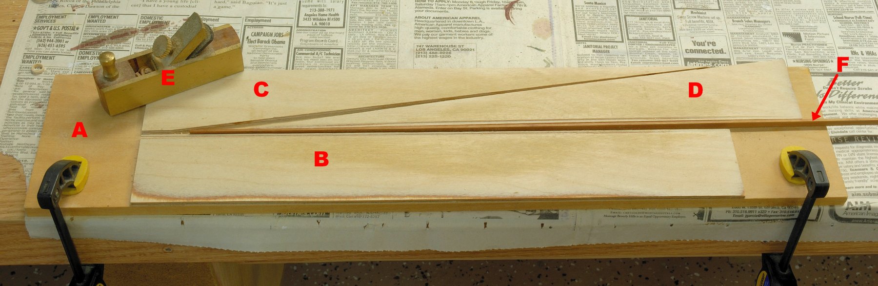
Here is how I shape (spill) my planks. First, build yourself a simple jig - see a pic below. A- base from plywood clamped to table B- rectangle from ~ 1/8 in. plywood, glued to base A C and D - another identical rectangle, but cut diagonally into two triangles: C - glued to A, and D - loose between B and C E - small plane for shaving the planks F- plank locked between B and D After carefully ticking off points of plank widths corresponding for each frame/bulkhead (a distance [taken with proportional dividers or a strip of paper] between two battens on your hull), and transfering them onto your plank, place TWO identical planks in the jig between B and D and clamp them tightly in the jig. (each plank will be for each side of the hull - after shaving them TOGETHER to the required shape, they should be identical - which you want them like that, since both sides of the planked hull should be identical) and besides, you want to make your work faster and simpler, don't you? Connect the above mentioned points into a curve on your plank, using a spilling curve, a French curve (best made from metal, like aluminium). Clamp both planks in the jig in such a way, that the plank with marked pencil line is facing you, and start shaving them carefully with the plane E - almost to the pencil line, but not quite so. When you are almost there, finish shaping the pair od planks exactly with sandpaper glued to a paint mixing stick or similar, but sand each plank under certain angle rather than 90 degs. The plank facing you - sand it with a bevel towards you, the other one - in the opposite direction. This will allow you to mount each plank on the hull very neatly and tightly next to the neighbouring plank and without ugly fissures in between. Repeat the above for the next pair of planks and continue so. Plank each bulwark with one plank and then go to the other side (bulwark) with the second plank, rather than planking straight ahead the entire bulwark and then continuing with the opposite side. This will prevent undesireable warping of the hull during drying off the moist planks (after you wet bent them). I built this simple jig many years ago, following advice from the now defunct Seaways List, and to this day the jig still serves me well, saves lots of time and makes my planks very exact. Greetings, Thomas PS: In addition to the above mentioned (excellent) sources of info on planking, I also wholeheartedly recommend a brochure by the late Jim Roberts "Planking the Built-up Ship Model", which is a bit more advanced than the book by Mastini, but explains clearly all problems a modeler might encounter during his/her build. The brochure, to my knowledge, is still available from Model Expo.

-
Gorgeous ropes, all of them! I wonder, did you try to twist any left handed ones as well from your threads? Fantastic looking ropewalk!
-
Doris, I would like very much to see your sculpting tools. A couple of pics, please, if possible?
- 1,035 replies
-
- 6
-
-
- royal katherine
- ship of the line
- (and 1 more)
-
ALL ropes look fantastic to me!