HOLIDAY DONATION DRIVE - SUPPORT MSW - DO YOUR PART TO KEEP THIS GREAT FORUM GOING! (Only 20 donations so far - C'mon guys!)
×


Dziadeczek
-
Posts
645 -
Joined
-
Last visited
Content Type
Profiles
Forums
Gallery
Events
Everything posted by Dziadeczek
-
 Delightful! How did you make those perfect spirals, if I may ask?
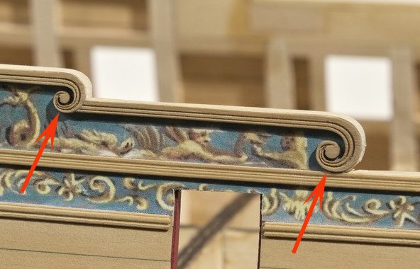
- 607 replies
-
- 4
-

-
- winchelsea
- Syren Ship Model Company
- (and 1 more)
-
Perhaps, while you pre bend your wet planks to fit the hull, you should also try to edge bend them a bit with your hot iron. Attach (glue) them only if they lay perfectly on the hull - that way you will avoid these gaps. Also, earlier on, you were right with those Polish markings: the letter L in Polish means strona "Lewa" (left) and the letter P means Prawa (right) side of whatever. I still remember my Polish, after leaving the country 40 years ago (!). So, if you have any problems with understanding your instructions, ask me and I'll try to translate this fragment for you, OK?
- 179 replies
-
- 5
-
-
- shipyard
- wütender hund
- (and 1 more)
-
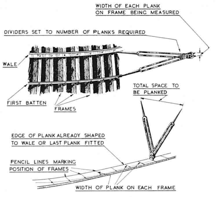
John, From my own experience, cheap plastic proportional dividers with thick, short and dull legs aren't good enough for this task. The legs should be thin and pointy, adjustable like from a good quality compass. Before you use them, calibrate them carefully, making sure that the distance between the shorter legs is an exact fraction (1/2 or 1/3, or so...) of the distance between the longer legs, adjusting the lenght of the legs. The ratio should be set up before with the central screw. Purchasing good dividers is an investment for a long time, so if you intend to build just this one model, use a paper strip technique instead. Cheaper! The way I use them is, I first set the ratio to the number, corresponding with the number of planks in a given 'belt', say 5 and then take measurements between the battens (or marks on the bulkheads) with the pair of the longer legs. Then I switch the legs, place one shorter leg directly against the edge of the plank and with the other leg I delicately mark the plank, pushing it into the plank ever so gently that it is just barely visible. This is the width of your plank at the given bulkhead. I repeat the same for all bulkheads. In the end I obtain a series of micro holes in the plank, which I subsequently connect with a sharp hard pencil using a metal curve (aluminium) the so called ship's curve. I fix the plank in my plank shaping jig and carefully shave its edge with a mini plane and sand it fine, until I no longer see the pencil line. I actually shave a pair (2) of planks held together in the jig, each one for each side of the hull (since they should theoretically be identical). This way I obtain two identical planks at the same time. Also, it is a good idea to profile your shaved edge not perpendicular to the surface of your plank, but at certain angle, so when you place this plank against the others, it will form a very tight fit, since the surface of the hull is not flat but rounded up. When i proceed with the second pair of planks, I change the ratio to one number smaller than the previous one, adjusting the center screw to 4, and so on. After I fill the entire "belt", I remove the lower batten and proceed with the lower "belt". And so on, until I have the entire bulwark planked. Do not try to plank completely the entire side first and then go to the other side - you run the danger of your hull getting warped beyond repair. Better to mount one plank on the first side and then the second one on the other side and continue that way. The 'skeleton' of your model should be placed securely in a planking "shipyard" during the entire process of planking, to avoid warpage. Check the pic attached below. The way to edge bend is shown on the video by mr. Kammerlander, I mentioned earlier. Take a piece of flat wood, like a piece of plywood and hammer there two small nails about 1 inch apart leaving them protruding up for about half an inch. Place the end of your pre weted plank flat on the plywood, in between these two nails and delicately try to edge bend it, at the same time rubbing it to and fro with your hot iron. Flip the plank on the other side and repeat the same. Do not burn the wood! The plank will quickly attain a new shape and become curved. This can be done to a certain degree, depending on the type of wood and dimensions of your plank (thickness), before the plank breaks. For tighter curves you have to preshape your plank like a crescent from a separate piece of wood - following the advice of David Antscherl or Chuck Passaro in their tutorials here. Good luck! :-) Thomas
-
Hi David, With the exception of your garboard strake (which is almost straight) , the others can be slightly edge-bent by a hot iron to conform to the others and the general shape of the hull.
-
Hi John, If I may continue for a bit... You write that this is your first model. Well..., I would advice that before you start planking, you should first prepare yourself for it. Get yourself a pair of good proportional dividers (those with long sharp legs, looking like pins). That will shorten and ease the process of spiling and also make it more accurate. If, for one reason or another, you decide not to use proportional dividers, you have to rely on a paper strip method, which is also good, but a bit more tricky and lenghty. It seems to me, that you have mastered the idea of subdividing the bulwarks into several "belts" by temporarily attaching thin battens and subsequently subdividing each "belt" into areas filled with your planks. Measurements have to be taken for each frame/bulkhead to determine the width of the plank there. Also, get yourself a suitable plank bending device that will work for you (some people use a curling iron, others a hot lightbulb, glass jar or a kettle, or a dedicated plank bending iron, I use a modified soldering iron with attached crescent shape head). Also, build yourself a plank holding device from scraps of wood and obtain a mini shaving plane. Place your plank in this holding vise and, after drawing on it the curve with a pencil, carefully shave and sand one edge to this shape. For me, one shaved edge is enough, if you want to shave the other, go for it. After the shaving of your plank, wet it in luke warm water for a few minutes and bend it to the shape of your hull, where the plank willl be laid down. Do it outside of the model, placing your plank on a straight wooden surface ( a piece of plywood, or such), and with one hand rubbing the plank back and forth with hot surface of your bending device, the other hand gradually lifting the plank to the desired shape. Repeat as many times as necessary. Some degree of edge bending will also be possible. If however your plank breaks while you edge bend it, you must fabricate it from a separate piece of wood, with this crescent shape bend designed into it. Look into David Antscherl and Chuck Passaro's tutorials for details how to do it. Also read this thread: Check the technique of Mr. Kammerlander (video there), especially relating to the edge bending. Once you get your plank bent, nicely matching the curvature of your hull, place it on it. It should lay there almost completely on the edges of your bulkheads, without forcing it there by the glue. Apply the glue to the places on the bulkheads where the plank will be touching them, and also along one edge of your plank and attach it in place. You may need a few pins or pushpins to keep your plank in place while the glue is drying (but don't push them through the plank but rather next to it to avoid unsightly holes afterwards), , or instead you may use a small drop of CA glue here and there to "grab" the plank quickly and keep it in place, while the yellow glue (titebond) is drying. And remember, the length of a plank should be from the bow to the stern. Avoid the situations that your planks end abruptly somewhere in the middle of the hull, with sharp point tucked under another plank laid above! Have fun!
-
too much math theory and not enough of good practice...
-
Fantastic! Many thanks for this film!
-
Watch the video in the link (it is of lousy quality and in German, but you'll get the idea). Water+ heat + lots of patience. https://modelshipworld.com/topic/18868-anyone-using-electric-plank-bender/?tab=comments#comment-579808
-
Don't forget that there is also an excellent brochure "Planking the built-up Ship Models" by the late Jim Roberts. I actually learnt how to spil and plank based on this particular brochure.
-
Outstanding build! Asking just out of curiosity, what are you feequently drinking in your videos? Tea? Is the other 'distorted' voice, the voice of your son? Can we see him from time to time as well? Regards, Thomas
-
And I have these two:

-
Build yourself a mini version of the so called "bow string server", used primarily by the people who are into archery. Google the name and look into "Images" to find an idea that suits you, except yours will have to be a mini version of those for archery, like for example in here: https://www.midwayusa.com/product/1007416075 . (mine is a bit different though, but works just as well) . This is an easy project, a bit of scrap materials from your workshop and a little machining and perhaps soldering. It will serve you well for many years, in conjunction with your serving machine! This mini server will do the entire serving process for your ropes without your intervention. If your serving machine is electrically powered, start the motor after suspending the bow string server under your rope to be served and go and make yourself a cup of coffee, the machine will do the rest for you. (Mine is a bit longer than the commercially available ones, so I can serve longer pieces of ropes, say 3 or 4 feet long, if neccesary). I quess, the mystery behind serving is that the thread is tightly woven (served) around your rope, without any spaces in between, because each consecutive winding is directly next to the previous one, in other words, the next winding doesn't have any other place to be put, except the place next to the previous one. (provided that there is a proper tension on the server). Such a mini bow string server takes care about "finding this place", so to speak. Also check this discussion here:
-
Photo Etching - do it yourself
Dziadeczek replied to Dziadeczek's topic in Metal Work, Soldering and Metal Fittings
Perhaps, Wefalck, you are more experienced in photoetching than me. I was a complete greenhorn in it, starting from point ZERO! For me, strangely enough, preparing my artwork, and later on copying it onto laser transparencies, wasn't a problem. Just time consuming. The transparencies (my "negatives") turned out quite fine, enough details, sharp borders and nice b/w contrast. I saved them onto a thumb drive and took it to a nearby Kinko, asked them to photocopy them on laser transparencies, using their highest resolution and max. contrast. They turned out quite nice, certainly adequate for my purpose. Then, I tried to prepare my brass plates, sanding them into madness, sand paper, starting from about 1000 to 3200 grads. Then I didn't know if I shoud rinse the brass with some isopropyl alcohol or another degreaser. Mr. Berger later on told me that he doesnt' use any degreaser, just sandpaper and makes sure that the water runs off from his brass in "sheets" and doesn't "gather up". So, I stopped degreasing it, after having some problems with it. Than, there was a problem with applying a film (photoresist) on my plates, first removing the outer, curled up protective plastic sheet with sticky tape. It turned out that the photoresist, being very thin, was reacting differently, if I cut a piece from the bigger roll with an exacto knife, versus if I cut it with a pair of scissors. If I used an exacto knife, sometimes I had real difficulties separating this protective layer from the emulsion; that layer wasn't separating nicely, was tearing up the emulsion, and so on... Frustration! But when I used scissors, the separation along the edges was somewhat easier - I don't know why? Then, I had a problem with applying the piece of photoresist (exposed emulsion side down onto the brass). If I used a clear tap water to rinse the brass after sanding it untill it looked raw and shiny like a baby's behind, I would find that, after laminating the "sandwich", the tap water would be leaving blotchy, milky spots between the metal and the layer of photoresist, even though before the lamination everything looked perfect. These spots would later on make etching difficult and uneven. So, I started using distilled water for rinsing brass after sanding. That helped. Than, there was a problem with adequate exposure time in my home made UV light box. I had to determine the best time; not too short, because the emulsion would be too soft and the developer would wash away EVERYTHING, or not too long - than the emulsion would harden so much that the developer would not remove completely areas to be etched away later on. My optimal time turned out to be about 90 seconds (45 seconds on each side, while exposing both sides simultaneously). Generally, if you use a specific UV light source (with appropriate UV light lenghts), the exposure time is much shorter, that with using a regular incadescent lightbulb. And the etching process is more even. Finally, I had to determine proper concentrations of my chemicals. Mr. Berger gave me some tips, but it turned out that I was using a wrong developer. It was supposed to be Sodium Hydroxide. And mine was! I got it inexpensively from somewhere on line. And I was using 20% concentration - 1 part of this lye to 4 parts of water - like in Mr. Berger's tutorial. But my developer wasn't developing anything! I was getting more and more frustrated and started already to think about etching my plate in some kind of professional etching service. Then I changed my developer into the one from Micro Mark. A major difference! I started getting some results!!! From that point on, it was just a matter of finetunning the entire process. So, as you can see, there are multiple variables to determine before you'll start getting acceptable results. Then, in order to further improve the quality of your etched parts, perhaps one has to perfect further his artwork. I agree with you on this point. Also, one has to remember, that there are many other chemicals and processes used in photoetching, which require yet different variables to perfect it. I just was using Sodium Hydroxide for developer and Ammonium Persulfate for etching, trying not to complicate everything too much. :-) Best regards, Thomas -
2020 NRG Conference
Dziadeczek replied to kurtvd19's topic in NAUTICAL RESEARCH GUILD - News & Information
Today I got this from the museum in Oxnard: http://hosted.verticalresponse.com/1097421/208717a3bb/521811715/6e39eb3c0f/ -
You Sir, are nuts! (off course, in the positive meaning of the word). I am trying to pick up my teeth from the floor, after my jaw dropped after seeing your model! Regards, Thomas
-
Photo Etching - do it yourself
Dziadeczek replied to Dziadeczek's topic in Metal Work, Soldering and Metal Fittings
Hi Pat, Thanks for your post. To answer your questions, first of all, the home made photoetching process has a certain learning curve in it, if one has never done it before. There are several variables to tackle and adjust, depending on your chemicals, their concentrations, temperatures, thickness of your brass, your UV light source, and so on. There are no universal numbers, one has to figure them out through his/her trials and errors, because one uses different chemicals and different ligh sources. So, prepare for yourself adequate supplies of materials and arm yourself with plenty of time/patience. For first several trials to determine those variables, use small samples of your brass and chemicals, not to waiste them excessively. For sure, your first trial or two at least, will not turn out perfectly. So, be patient and try again and again, until you'll arrive at good results. Write down your variables to be used later as your standards. For most of your questions you'll find the answers in the above mentioned tutorial by Gene Berger, which is here: http://geneberger-models.com/photo-etching/ Here I will only signal some points to watch. I was using a rather thick brass plate = 0.01 inch (0,025 mm). For that thickness you'll have to etch it on both sides simultaneously to avoid excessive underetching (etchant creeping under the photoresist foil ruining details). You have to prepare your artwork as perfectly as possible, using one of the graphic programs, Photoshop, Corel or Gimp, or similar. Make your drawings in large resolution, 900 dpi, if possible. Everything has to be either pitch black or completely transparent, no grey areas whatsoever. Make sure your drawings are in the proper scale (size) - hence you see a ruler in my artwork. After printing both transparencies i checked one final time to make sure details were in correct sizes. After you are done, make a mirror image copy of it - for your transparencies pocket (see further). Then copy it on laser transparencies using a laser copier with settings of biggest contrast and biggest resolution. The more perfect your artwork, the better will be your etched plate. Once you have both transparencies mirror imaged, you have to create from them a pocket for your brass plate. Tape one transparency to a sheet of glass iluminated from underneath, with its matte side facing you. Tape the second transparency on top of the first, aligning carefully both, but this one with its dull side facing the first transparency. Carefully remove from glass pane both transparencies which are taped together along three edges, to form a pocket. You have to keep in mind that, if you are using a photoresist foil, the process is similar to analog b/w photography (a negative film vs a positive paper principle). Your transparencies have to be in "negative" of what you want to etch. That means, everything you want to be etched away, has to be black and areas to be left intact, have to be transparent. If you are using a photosensitive spray Positive20 (popular in Europe), this has to be in reverse, what'll be etched away has to be transparent and what has to be left intact, must be black. The carefull allignment of both transparencies is critical for a sharp edges of etched plate. Another critical variable is a super careful and detailed preparation of your brass plate - polishing and wet sanding with several gradations of fine sanpaper, until the surface is sparkling clean and shines like a mirror. Wear rubber gloves to avoid any grease spots from your fingertips. Do a final rinse of your plate with distilled water, which should run off the brass in sheets. Now, under UV protective light (a yellow bug lightbulb is OK) you'll apply a layer of your photoresist to both surfaces of your plate . This comes in a roll, sort of like a Saran wrap, covered in a black protective plastic foil, to avoid accidental light exposure. Unroll and cut a neccesary length of this foil (under the UV safe yellow light) and carefully remove the inner protective plastic layer from it's inside curled surface. The best is to use a short piece od Scotch tape taped to its corner and peel it off and discard, to expose super thin bluish layer of this photosensitive foil. Carefully place this foil onto your brass, the peeled off surface down, making sure there are no air bubbles trapped in between. Do the same on the other side of your brass. Place your brass/photoresist sandwich in a laminator and run it at least 2 times, back and forth. Check again for air bubbles - pierce them, if present, with a sharp point of exacto knife or a needle and run your plate through the laminator once again. Insert your plate/photoresist sandwich inside your transparencies pocket and finally, place this brass/photoresist plate in between two sheets of glass (quartz glass is best, obtained for example from an old copier or scanner) and clamp it tightly together. Place everything in your UV exposure lamp source and expose it on both sides for a predetermined time. This will transfer your artwork from the transparencies onto the brass - you should end up with a distinct black hardened outlines of your details on the photoresist attached to your brass. Remove this sandwich from your light source, unclamp both panes of quartz glass and remove the plate from the transparencies' pocket and store it somewhere in darkness until you are ready to etch. Until now, these are the most important steps, demanding great precision and dexterity, good eyes and patience, because you were working under diminished light - a bug yellow light. The end result of your etching will depend on how well you have prepared your plate. The actual process of etching is now just a matter of preparing your chemicals, pouring them into suitable containers, checking temperature of your etchant, removing second outer protective layers from a photoresist foil and developing your plate + a final etching of it. Everything on the specific chemicals, materials and where to obtain them from, and other details, you'll find in the above mentioned tutorial by Mr. Berger. I used a special etching plastic tank Gene is talking about, where I suspended my plate vertically and etched it hunging there immersed in etchant. This tank will control and maintain the temperature of your etchant (with a built in heater) and will do all necessary agitating with an aquarium style bubbler. You just sit and wait. Thomas PS: Sorry for my less than perfect English - after 40 years of living in the US, it is still my 2nd language. :-( PHOTO ETCHING HOME MADE instructions.pdf -
Photo Etching - do it yourself
Dziadeczek replied to Dziadeczek's topic in Metal Work, Soldering and Metal Fittings
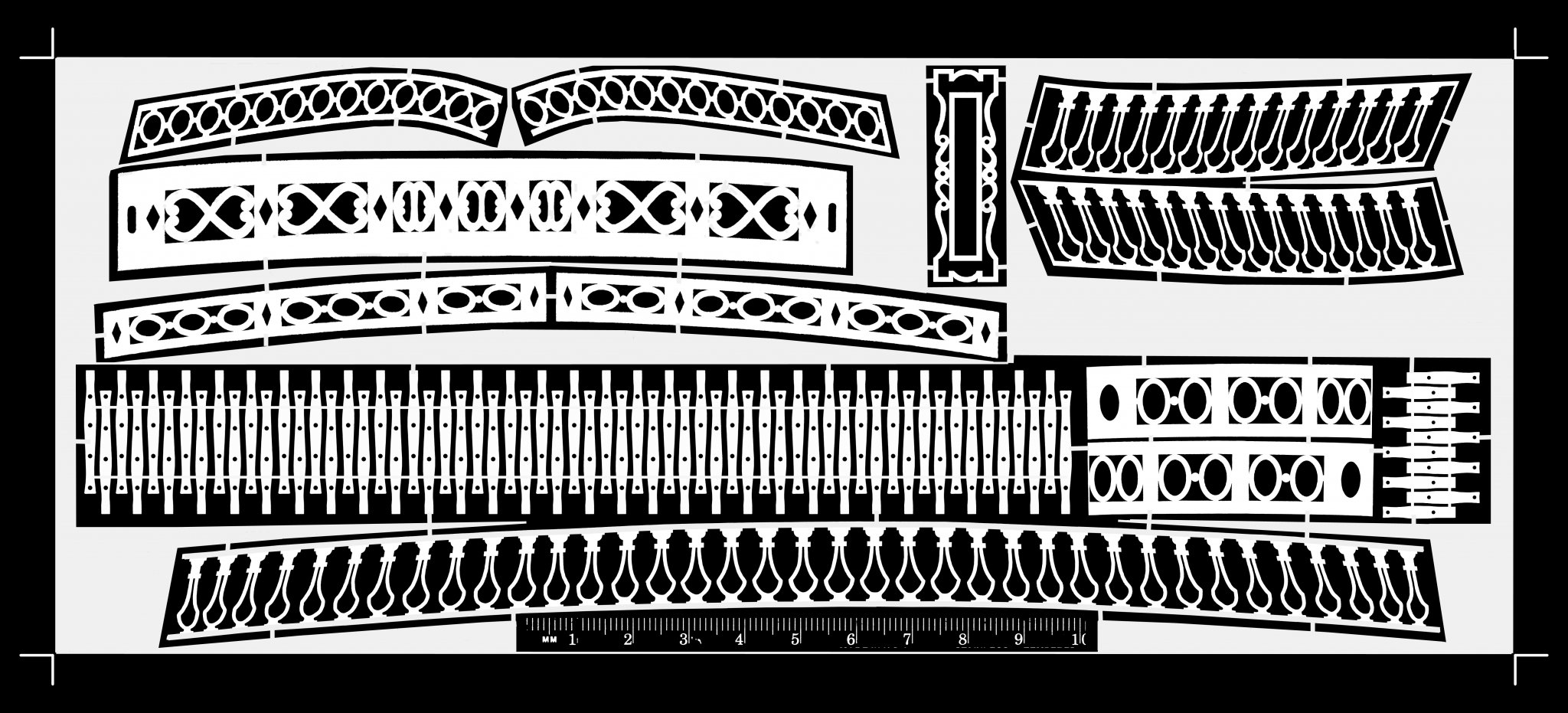
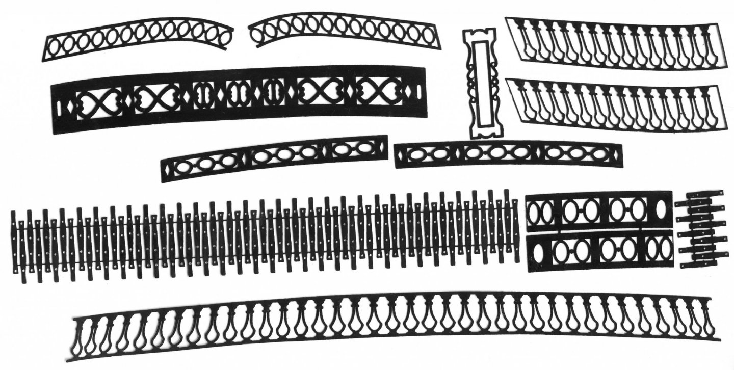
Hi fellow shipmodelers, It has been a long while since my previous post - time spent on my attempts to photoetch at home, as well as other home tasks, eg. staying alive and healthy recently, socially distancing myself, and such, but finally I have some constructive reporting to post now. I closely followed the online tutorial on photoetching given by Mr. Gene Berger, which was suggested earlier on by one of the members. Many thanks for it to the Gentleman. I also had a very pleasant telephone conversation with Mr. Berger himself, where he gave me some extra tips. Well, after many trials and errors and various changes into the exposure time and the concentrations of my chemicals, yesterday I finally managed to obtain an acceptable plate. It is not perfect, but it is good enough for my model (Boudriot's 74 guns in 1:48). What I did is, first - I had to change the cheap developer from some generic Sodium Hydroxide I obtained somewhere online, into the one from Micromark, because my generic NaOH simply did not want to develop anything and subsequently my etchant could not etch anything. It turned out to be a big lie rather than lye . :-) Waisted that way lots of time and material! Also, I managed to pinpoint the best exposure time for my UV lamp I built earlier. It turned out to be about 90 - 120 seconds only! (45 to 60 secs on each side). The UV light in there really takes care of the photoresist quite quickly, as opposed to the ordinary incandescent light or unpredictable sunlight. The first trial of a partial plate with the above settings - and the first time a modest success! Voila!!! My second time - this time with the whole plate rather than its part only, turned out to be not so good. I found out, that the chemicals, both the Micromark developer and the etchant (ammonium persulfate - in my case) are rather unstable and quickly degrade, not just after the first process of etching, but even after a few days, being stored in plastic containers (bottles) and they produce unexpected and unacceptable results - partial, blotchy etching in places and overetching elsewhere. So, yesterday I decided to prepare brand new chemicals and yet another new brass plate and start all over again. I warmed the etchant to 42 deg C and started the whole process after succesfully developing it. After a few minutes I noticed that the temperature of etchant in the tank was rising. Towards the end, when all elements were about etched, the temp was already 65 degrees C! I think that this was due to the size of my plate 4.5 x 10 in. - quite a big area of etching. This must be quite an exotermic reaction! Anyway, to make the whole thing short - after 30 minutes of etching, the plate was done! See the attachments. I enclose two attachments, the first one shows my artwork I prepared on the Photoshop, and the second one - etched elements from yesterday, shows my parts after the etching. I cut them out with small snips and freed them from the rest of my plate and blackened them with Birchwood Casey - the one for brass/copper. Here I loosely placed them in the same manner as they are on my artwork - to compare both. In conclusion, I have to say, that the entire process of photoetching at home is certainly doable, (though quite tricky), however one must prepare oneself for it beforehand. Firstly, obtain or build a suitable UV exposure lamp, get a laminator, get a few plastic containers for developer and water, get a good etching tank with temp control and a bubble agitator and all neccesary chemicals and photoresist. Very critical to the entire process is to properly prepare the brass plate, to be as close to perfection as possible, shining like a mirror, free from any debris and grease from your fingertips. Use only distilled water for the entire process. And also the process of applying photoresist onto the plate is quite finicky. Observe exact UV exposure time! If you do everything properly, the rest is just patience - exposing your plate in the chemicals and waiting for the results. I had lots of experience with an old fashioned B/W analog photography from my earlier, young years, but this process, although somewhat similar in principles, is more demanding and unforgiving. You have to be more exact throughout it, for any deviations will result in unexpected and undesireable results.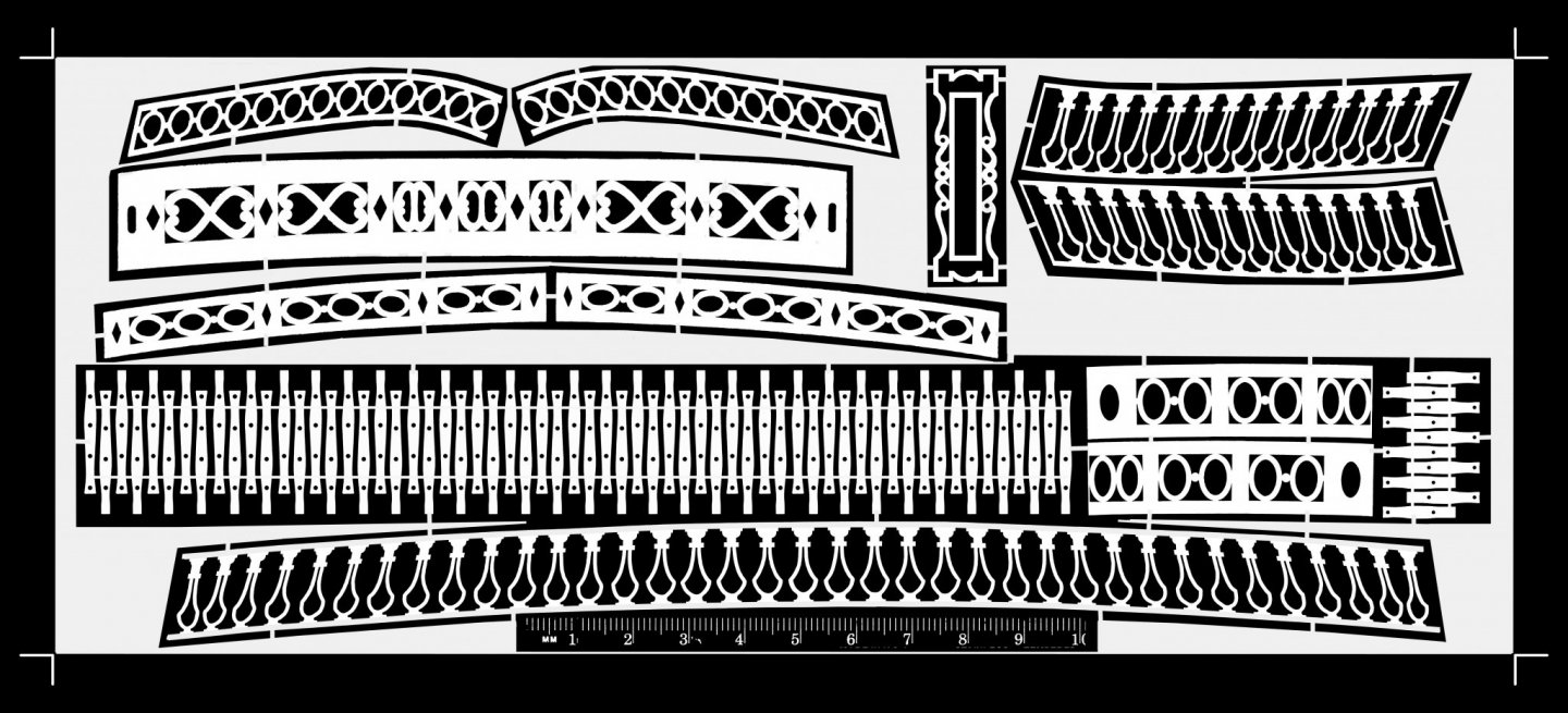
- 28 replies
-
- 10
-
-
Mike, You should have the possibility to change the white ballance in your camera as well. Set it to "incandescent" and, if it is necessary, furthrer tweak the ballance in post prod - if you shoot in RAW. Also, if you can set your camera to aperture priority mode, select the smallest f. stop, for example f.22 and your camera will automatically choose appropriate exposure time . This might be some long time, a few seconds or so, but you said, you are using a tripod, so who cares, you are not chased anywhere and can wait... This small aperture will give you deep depth of focus, everything from close by to most distant details will be sharp (well,... almost, for in order to truly get EVERYTHING razor sharp, you have to use a technique called "focus stacking". But, I am sure you know about it already...) Also, I found out that the best light for photographing models is using daytime light, outside, but in a cloudy day, not direct sunlight. Admiring your modeling skills!!! :-) Thomas
- 607 replies
-
- 3
-
-
- winchelsea
- Syren Ship Model Company
- (and 1 more)
-
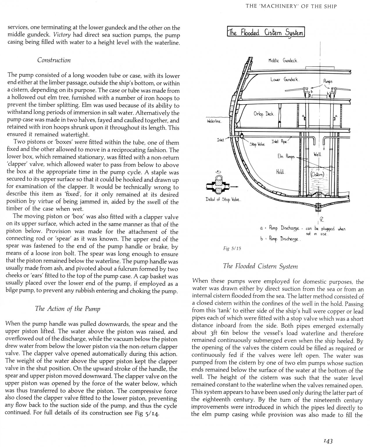
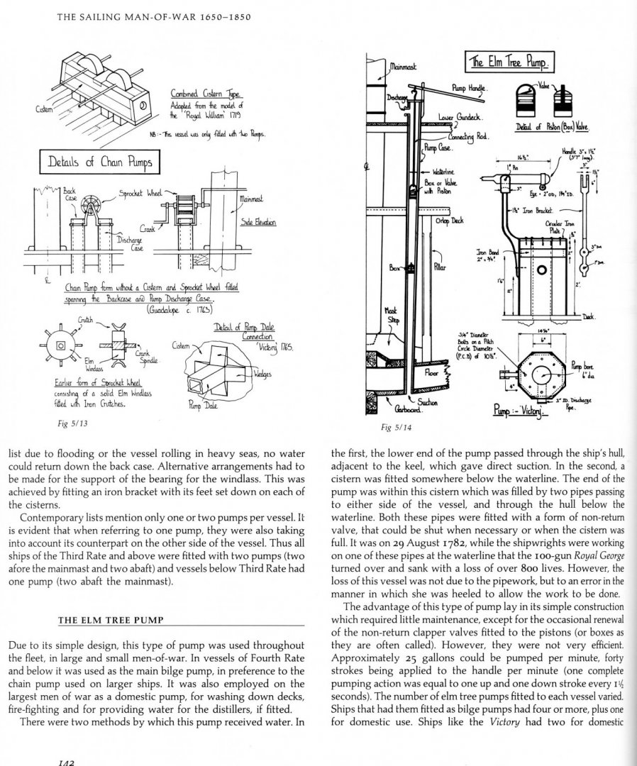
On p. 142 I scanned above, it is stated that the cyllinders were made of elm, which is very hard and moisture resistant wood, additionally reinforced with iron rings, and this simple construction was very robust, requiring little, if any maintenance, only occasional replacement or greasing of the boxes (valves), so it is quite unlikely that these barrels were susceptible to cracking/ breaking, unless being directly hit by the enemy's fire during a battle. The text also says that the pump was capable to extract (suck) about 25 gallons of water per minute. I imagine, that if the barrel was cracked/broken, similar amount of water would rush into the bilges. Considering the size of the hull, this wouldn't be so much - after all, there were other pumps onboard to use... Jean Boudriot says that in French vessels, the working part of this barrel was made from a bronze pipe, only upper and lower ends of the pump were made of elm. As we know, bronze is quite strong, unlikely to crack or corrode. It is used even nowadays for plumbing in certain countries, e.g. Germany... I fully agree with you all, that the life onboard those vessels was very dangerous (not even considering loosing one's life during a battle, where opposing forces were desperatly trying to kill each other!). Even after all these years since then and numerous improvements, it is still one of the most dangerous occupations today! BTW, I found out in B. Lavery's book an illustration, showing a combo-elm pump, which allowed drawing water from both sources, either an inner cistern or directly from the sea. Interesting... Stay safe and healthy, Thomas
-
OK Bluto, here is the previous page nr. 142 from the above mentioned book. This should give you further explanations to your questions. Not being any expert on pumps, I think that the water let inside the hull through those horizontal pipes from the openings in the bulwarks below the waterline, was directed into the watertight cistern, and from there it was sucked up, onto the decks by means of the elm tree pumps, to be used for cleaning the decks and/or for extinguishing fires, or such. An alternative was to draw water directly from the sea, without this cistern - look on the pic 5/14. The stale water in the bilges was removed rather by the chain pumps - being more powerful than the elm tree pumps. (also, in the book "The Arming and Fitting of English Ships of War 1600-1815" by Brian Lavery, there is an entire chapter (13 pages!) devoted just to pumps. If you read it, you'be an expert on the topic, for sure!) :-)
-
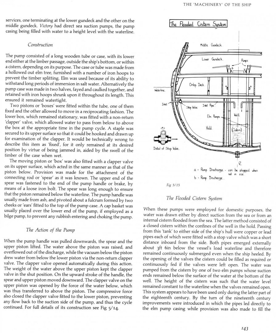
There is a pretty good explanation on the anatomy and function of the elm tree pumps, as well as this so called "flooded cistern system" on pages 142 & 143 in Peter Goodwin's "The Construction and Fitting of the English Man of War 1650-1850". I am attaching a scan of p. 143 here. Also J. Boudriot talks about pumps in vol. 2 of his '74 gun ship", and even though those are French with small differences of their details, the principle is the same. Regards, Thomas
-
After I twist my ropes on a ropewalk, I always stretch them a bit in my hands. The ropes are like rubber bands, so they will slightly stretch and the individual strands at the same time will "lock in". Any ugly "fuzziness" I burn away over a flame. Then I pull them through a chunk of bees wax two to three times and again pull them tightly between my fingers to remove excess wax. The heat generated will also melt the wax which will sink in. I make my ropes mostly from cotton crocheting fibres, not from polyester, which is even more 'rubbery'. On my Corel's "Victory" (bashed) the shrouds retained initial tightness after more than 10 years.
-
If you can locate a medical needle of appropriate (to your scale) thickness or other steel tubing, cut off its end and sharpen the edge. Press and twist it into the decking to obtain small circles - this will give you great looking simulations of your treenails.
-
I didn't realize that his is double planked. If so, I still would order more planks, remove those upper ones, and repeat upper planking, making sure that they come into the rabbet in the stem as well as the sternpost. Perhaps they were originally too short? Maybe, as ASAT suggested, he should cut those upper ones in the middle of the hull and replace those shorter pieces with new ones, saving on work and material, but I would stagger the butts to look more naturally. Before attaching a garboard strake, I would detach a false keel from the keel and file off edges on both surfaces, thus creating a, sort off, groove after glueing them together. This would became a rabbet, where the planks' edges would go. By the way, he said that his planks were pre-cut, but he didn't mention that they were also pre-spiled. If so, I still wouldnt' trust the kit and spile them myself. My three pennies...
-
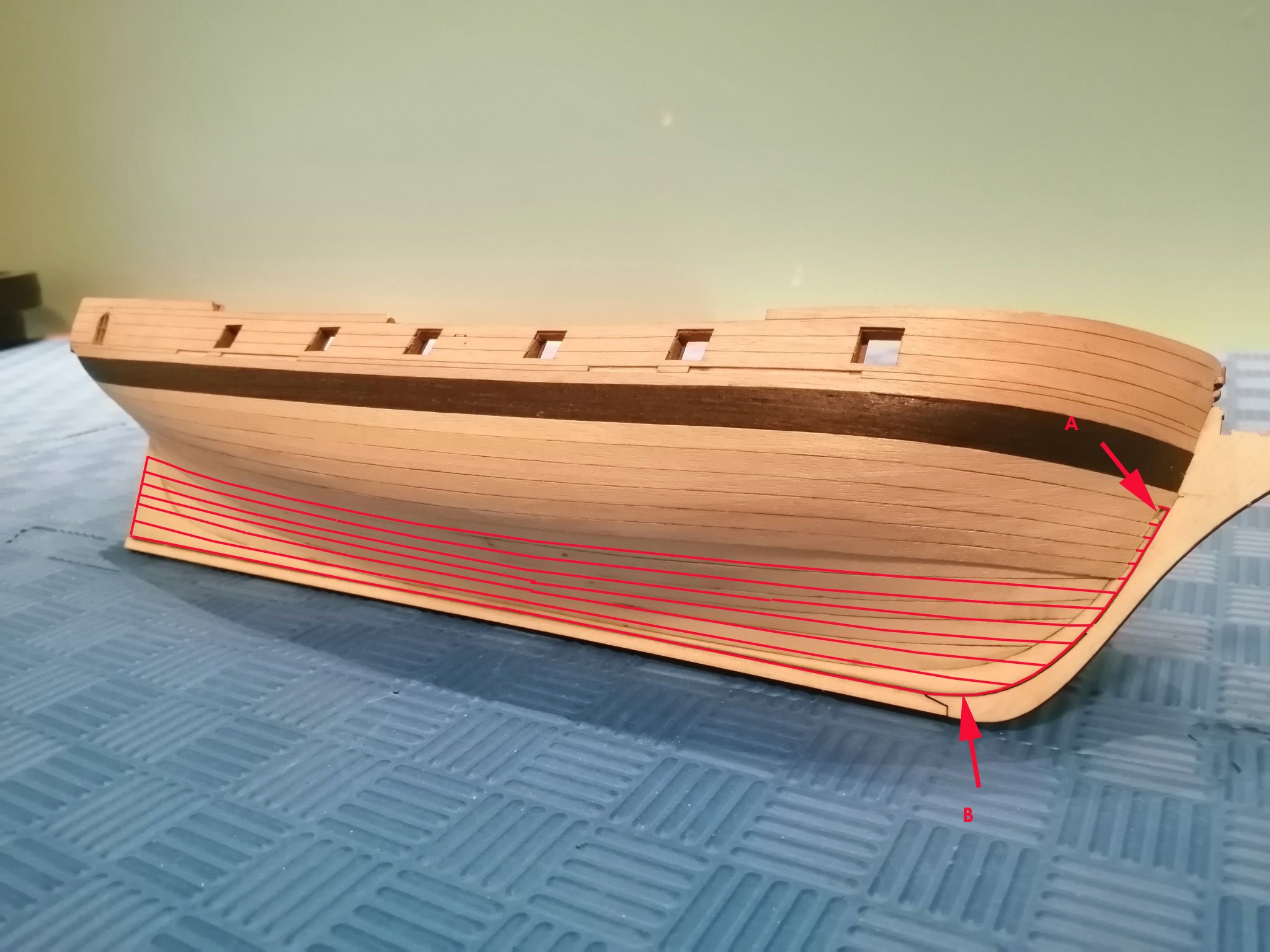
I am afraid he is not only talking about this hole marked in my pic as "A", but he didn't properly do spiling of his planks and did not run the lowest plank (garboard) all the way to the bearding line - as "B". Also, his planks don't abutt into the bow section of the keel (into the rabbet) but end before it. Kalakukko, do yourself a favor and read a couple of tutorials here on planking the hull by David Antscherl and Chuck Passaro and, after obtaining extra replacement planks from Korabel, remove wrong planks and do the spiling (determining the correct run) of your planks,- replace them, and everything should be OK.