


Glenn-UK
-
Posts
3,005 -
Joined
-
Last visited
Content Type
Profiles
Forums
Gallery
Events
Posts posted by Glenn-UK
-
-
-
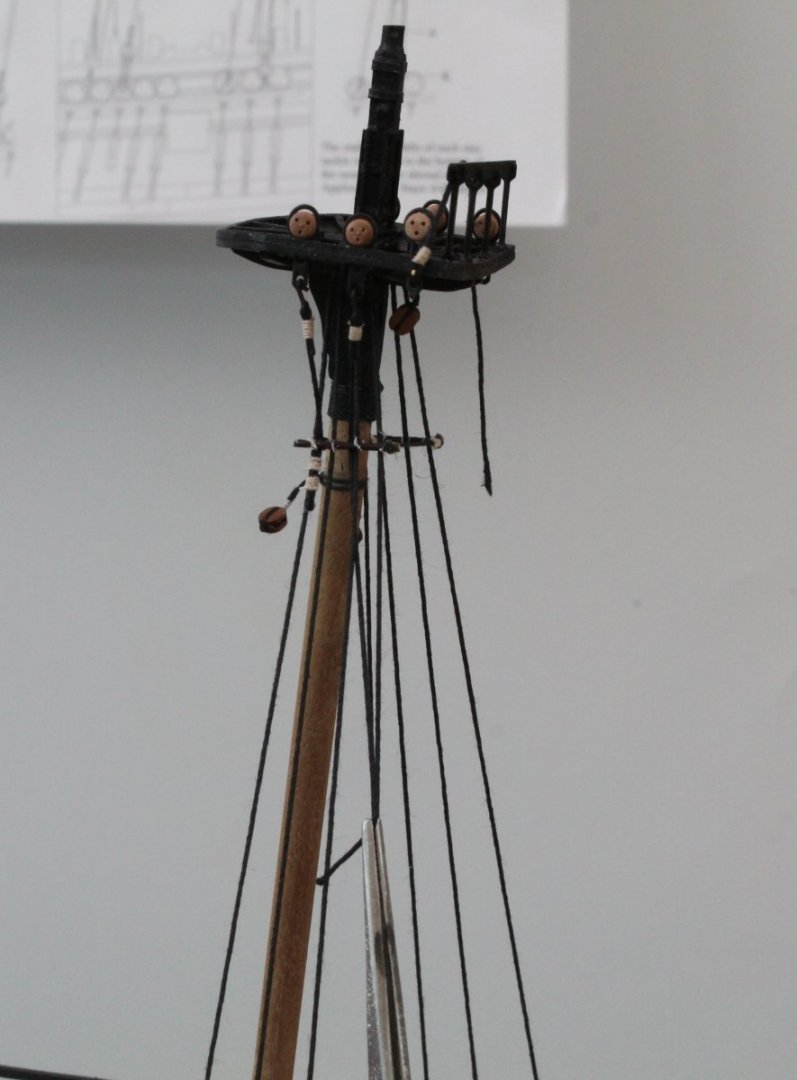
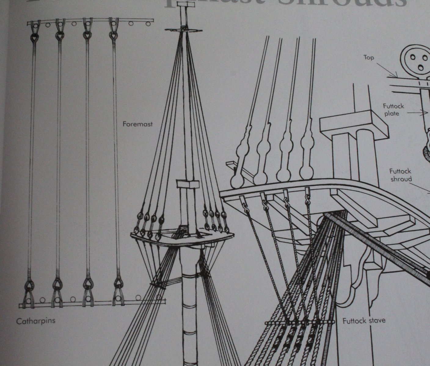
Ratlines - My Method
I use to start at the bottom and work my way up and I usually ended up with hourglass shaped shrouds. I changed to the method detailed in this post on the DOK build and then on my Alert build and it has yield much better results.
So here is my process
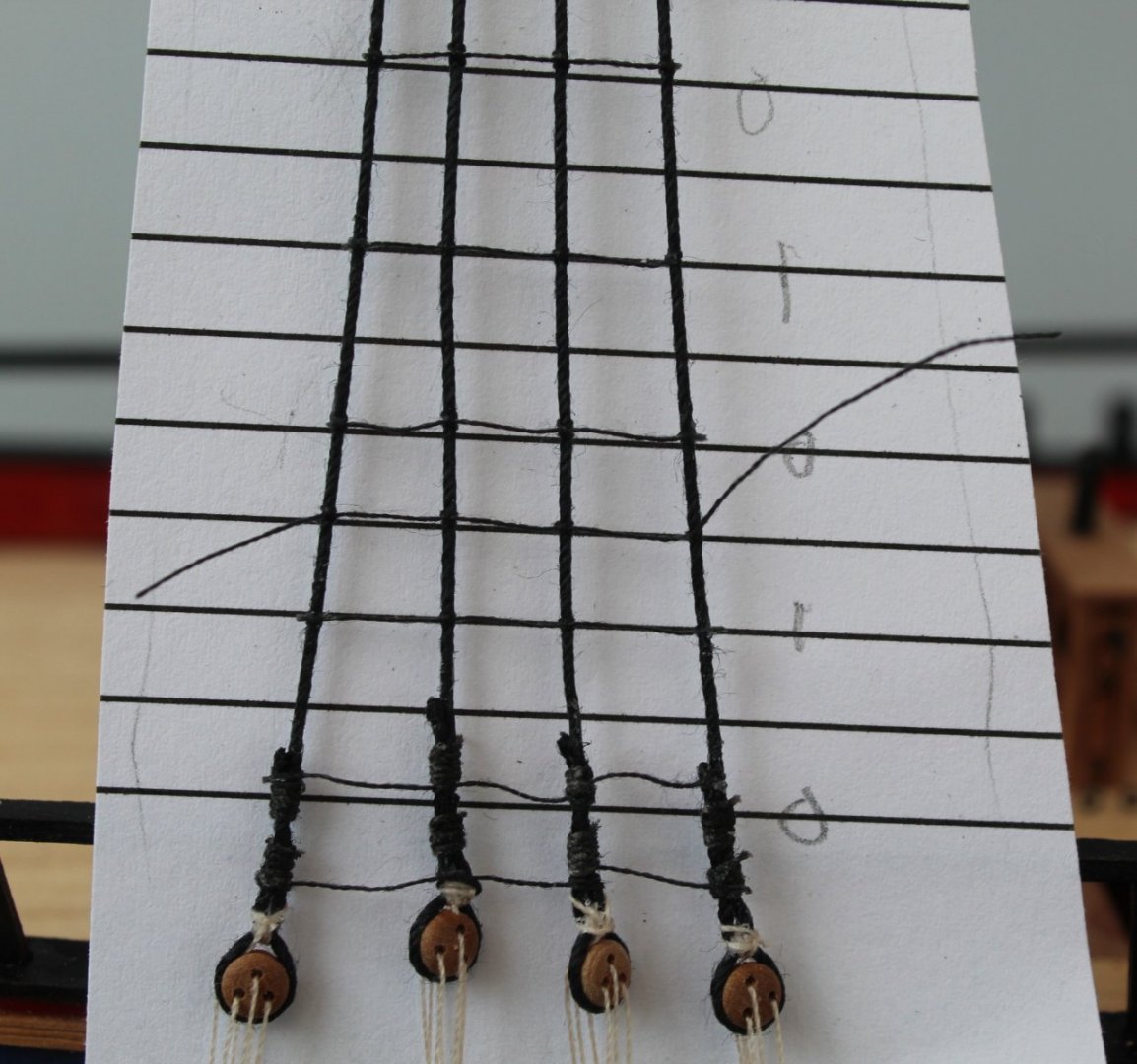
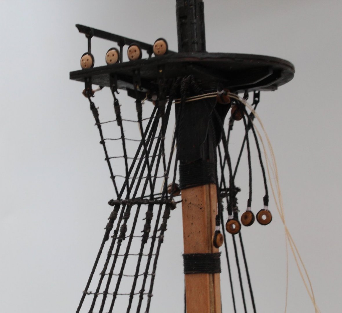
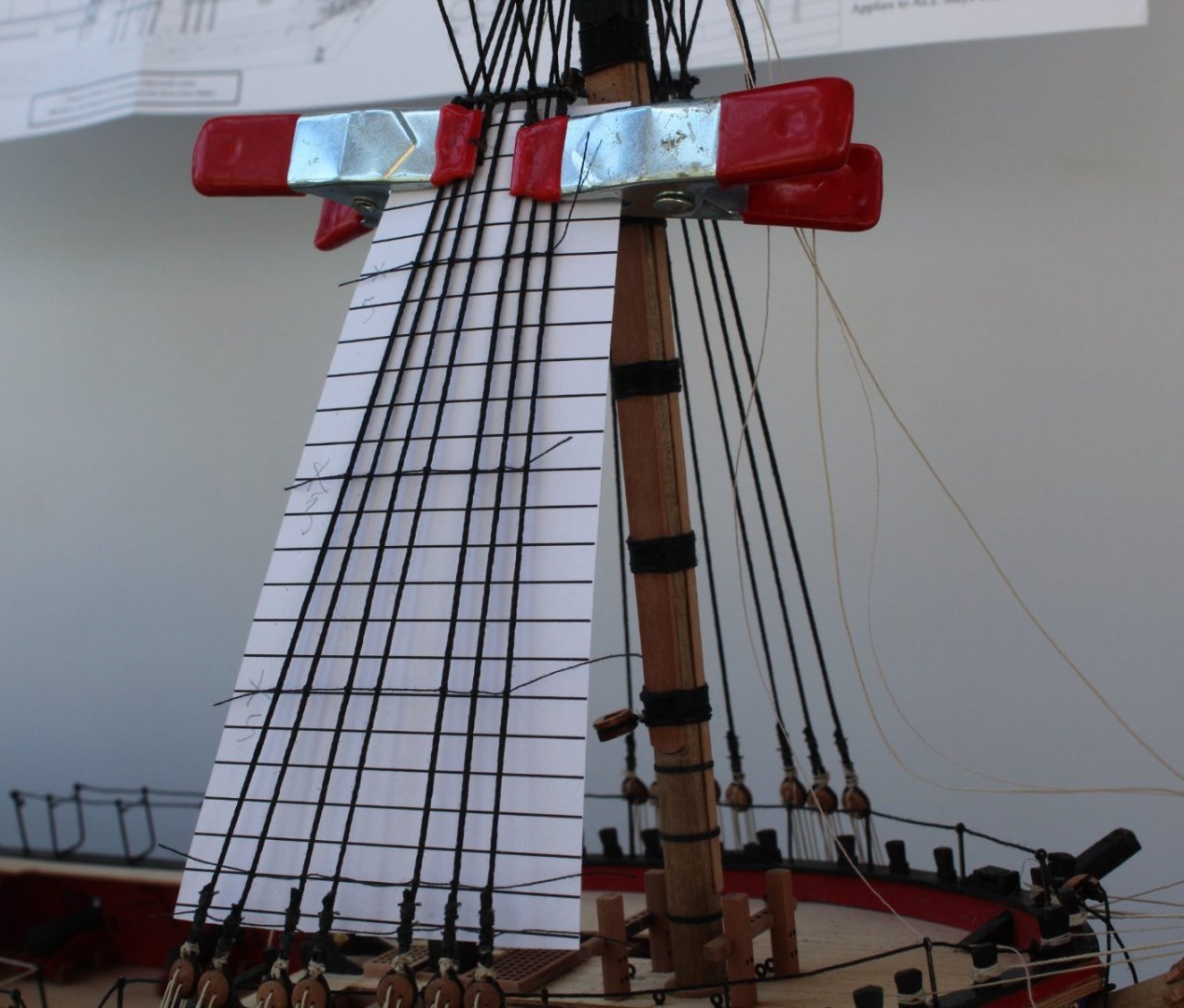
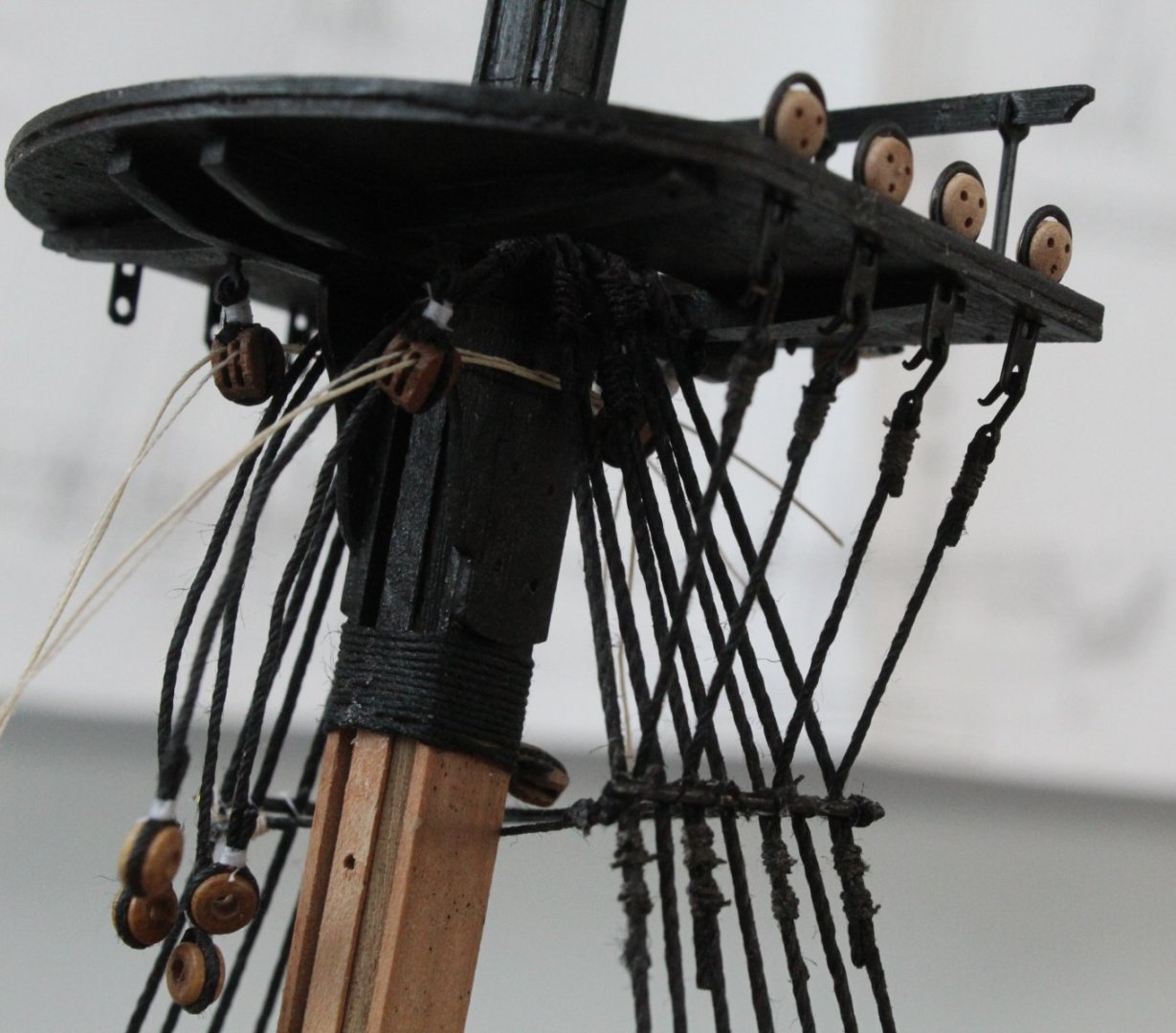
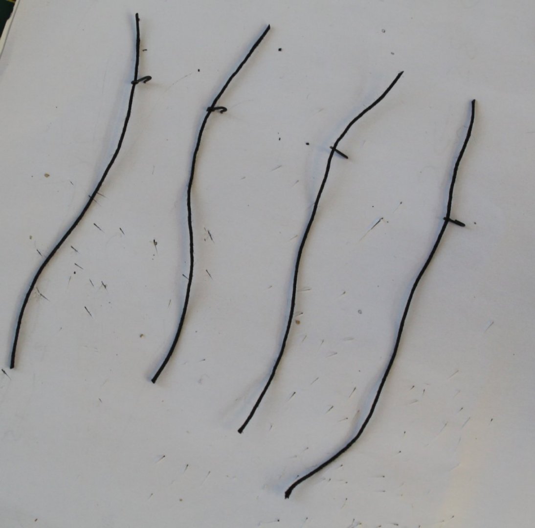
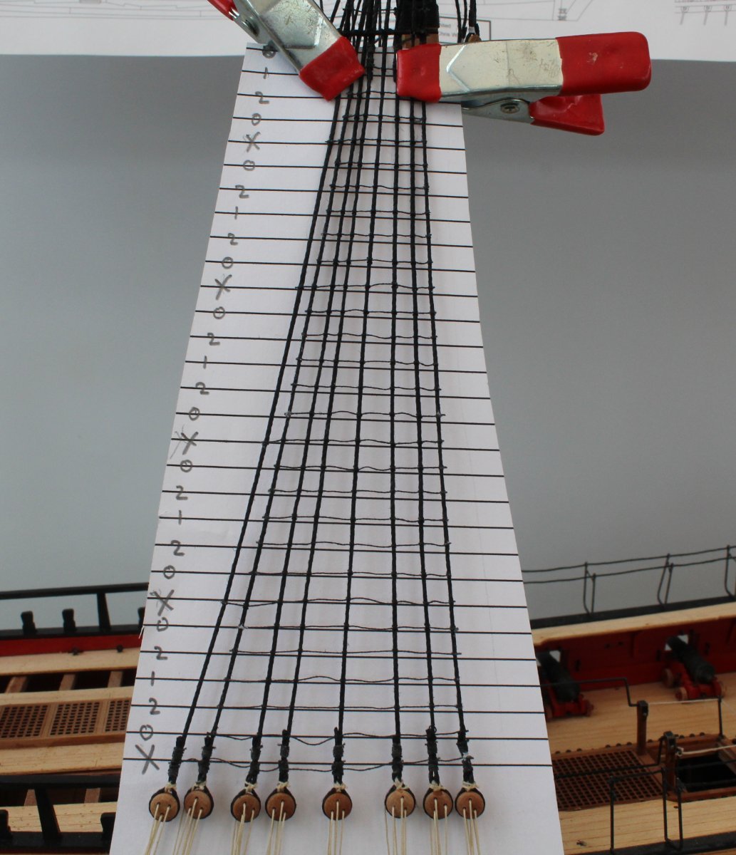
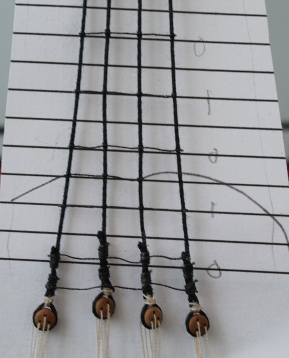
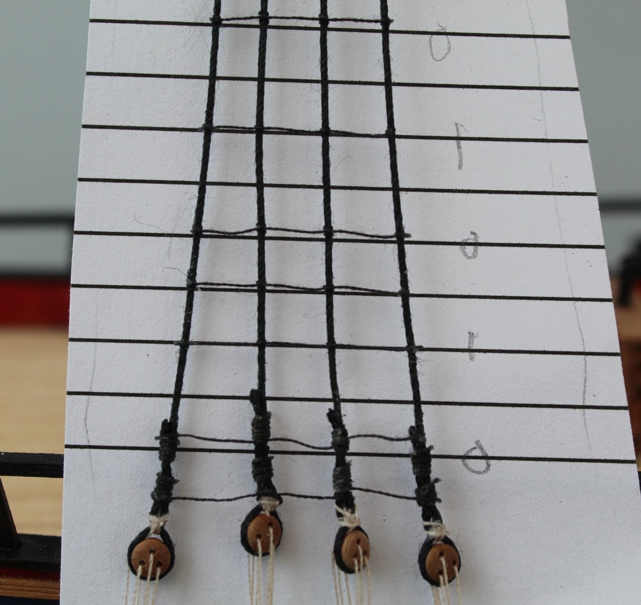
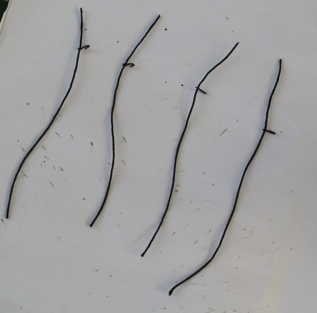
Looking at the plans I note the main mast outer stern side shroud only has a few ratlines, as can be seen in the picture below. As detailed in my post I opted for a 5mm spacing between ratlines to replicate the 13" spacing on HMS Victory at 64th scale
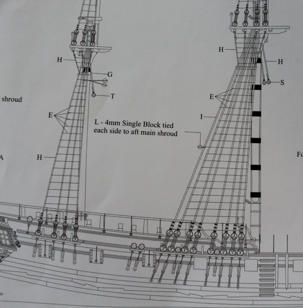
With reference to the next photo I print out a set of guidelines, with a 5mm spacing which is cut to shape an pinned to the shrouds.
On the template X indicates the full length ratlines which are the first ones to be added.
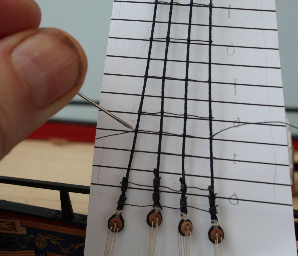
Next I add the ones either side of the X which are the ones indicated with on 0 on the template. After that I add the middle ones as indicated by a 1 and finally I complete the process by adding in the 2's. I tie a half hitch of the first shroud (which does not require a ratline 0,1 and 2) as I find it easier to then add the clove hitch knot to the first shroud. Once the ratline is completed I apply a touch a ca gel to the first and last clove hitch before I trim the excess thread. The half hitch can then be released from the first shroud line.
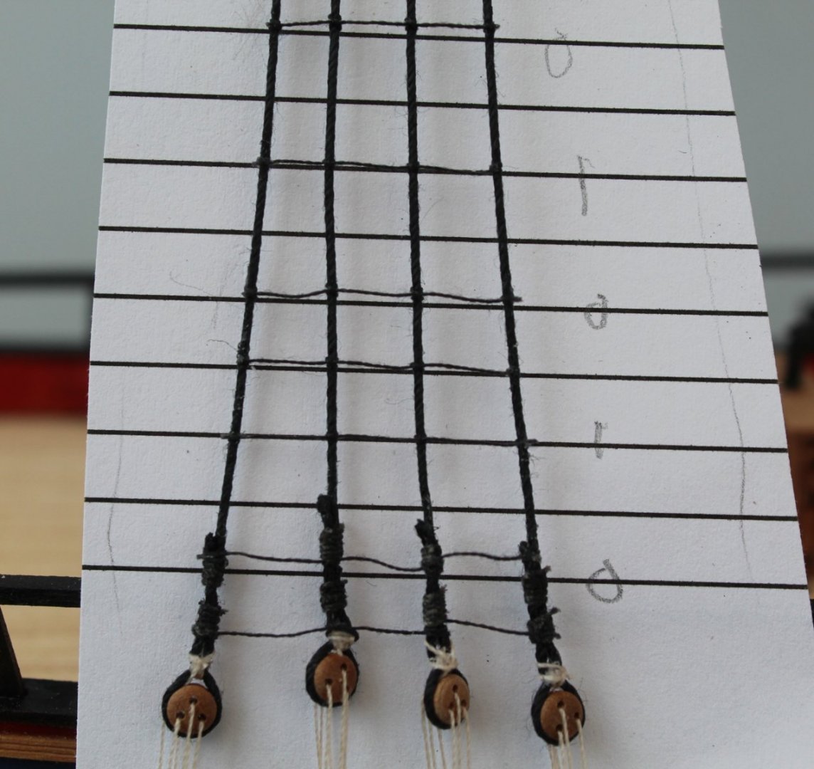
Once I have completed adding all the ratlines I will check and adjust the positions where necessary before I brush on a diluted pva solution over all the shrouds and ratlines.

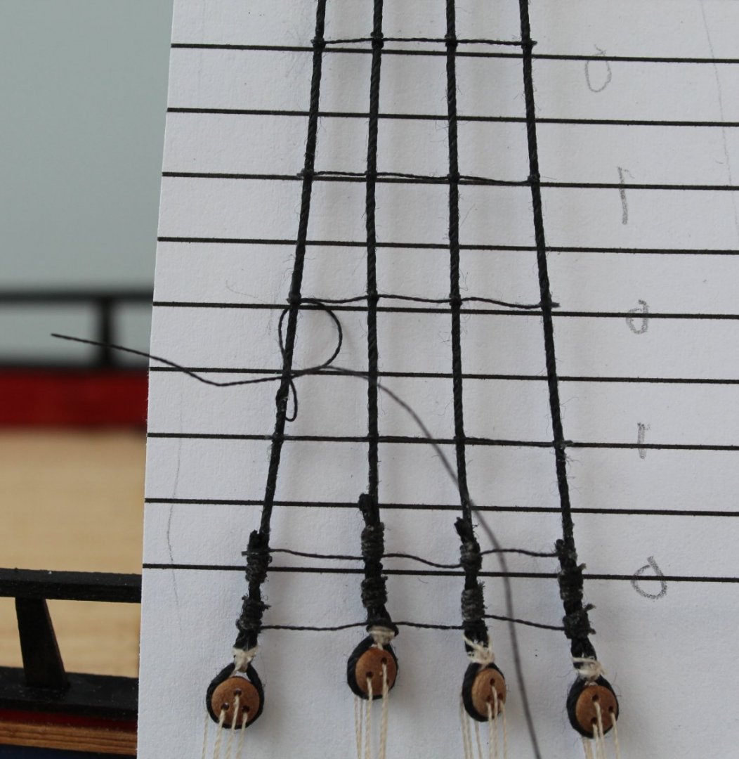
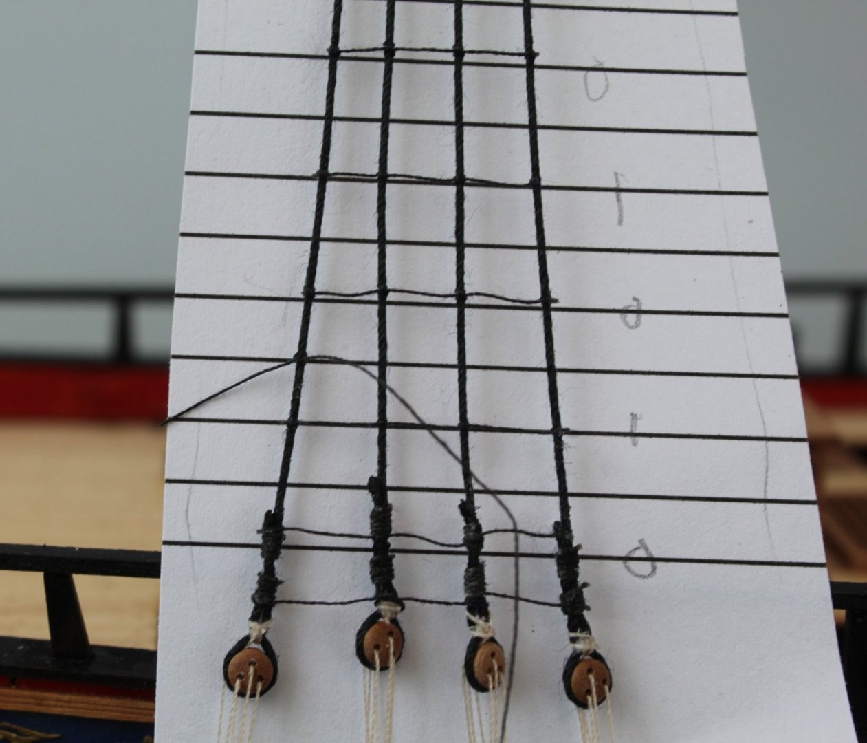
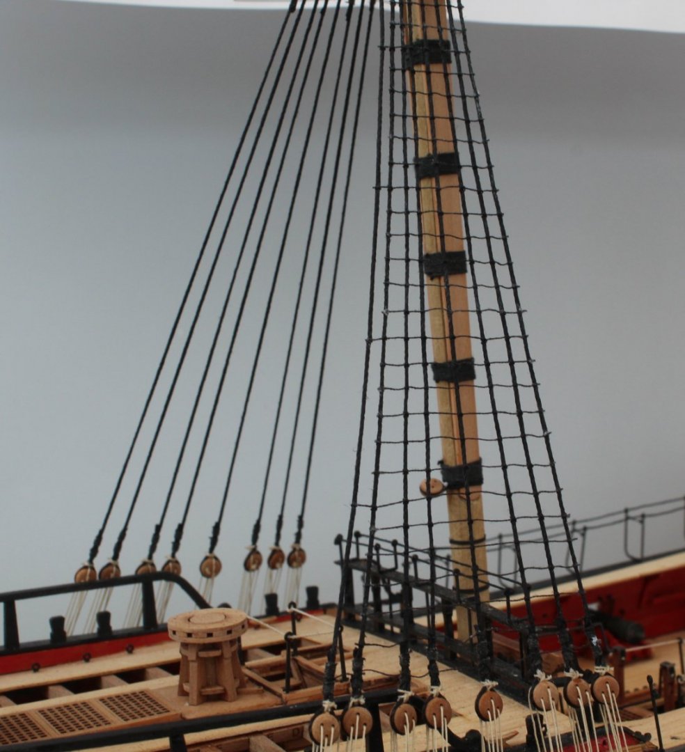
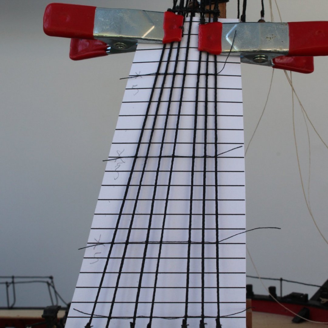
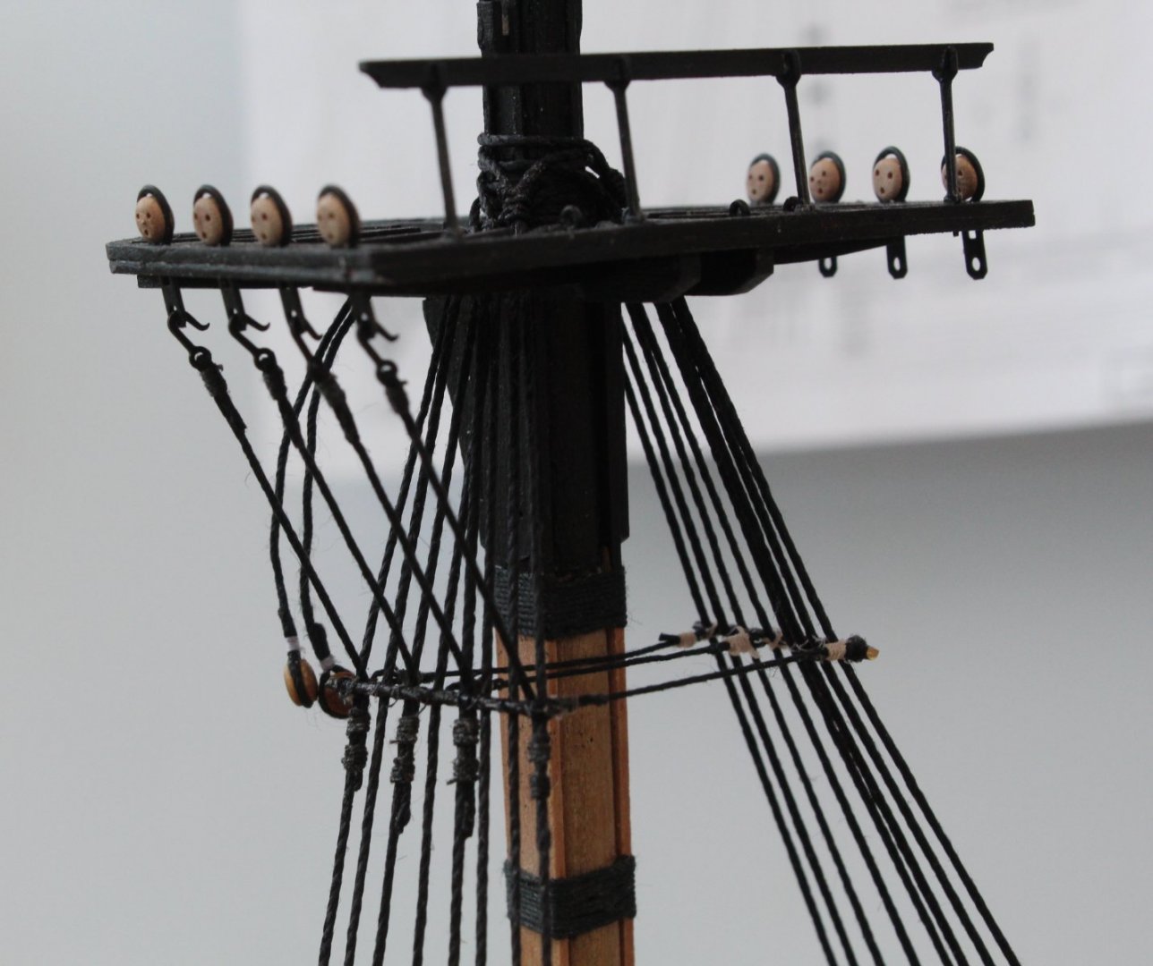
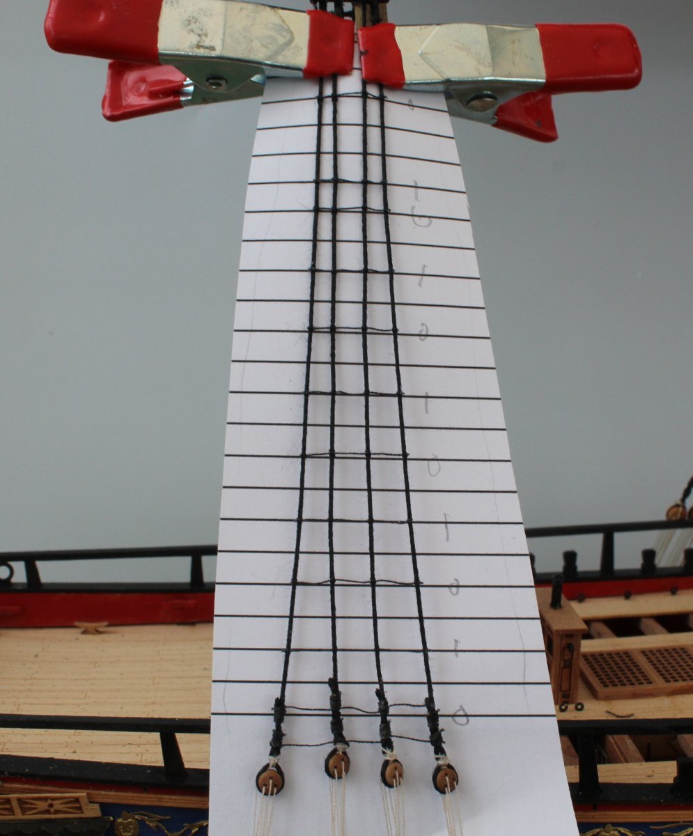
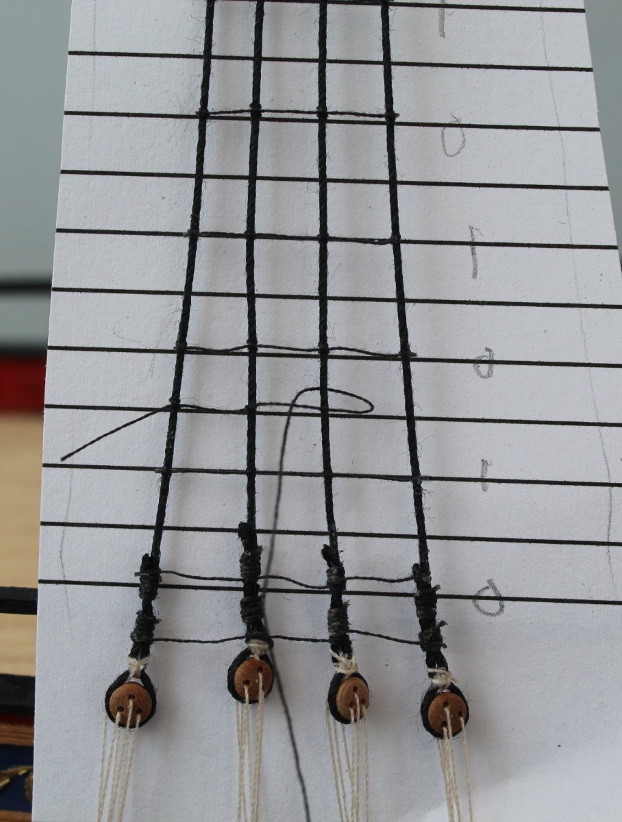
Moving on to the mizzen mast they are all full length ratlines. I started by adding every 5th ratline one as indicated by the 0's (see photo below). I then added the middle ones as indicated by the 1 which is as far as I got when I took the picture below.
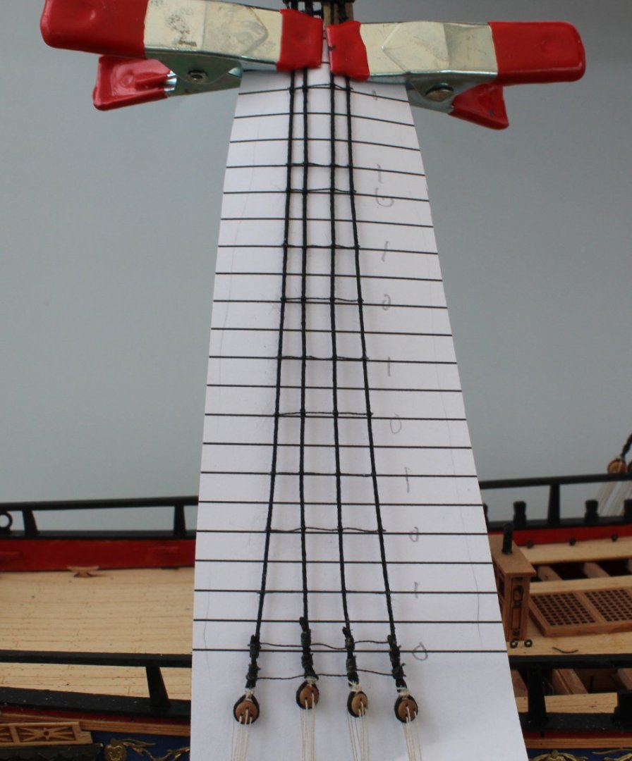
I will now fill in the missing ratlines. I have already added one near the top so now I will add on near the bottom and will continue to work in both directions alternatively.
I also like to work from left (stern) to right (bow) on the starboard side.
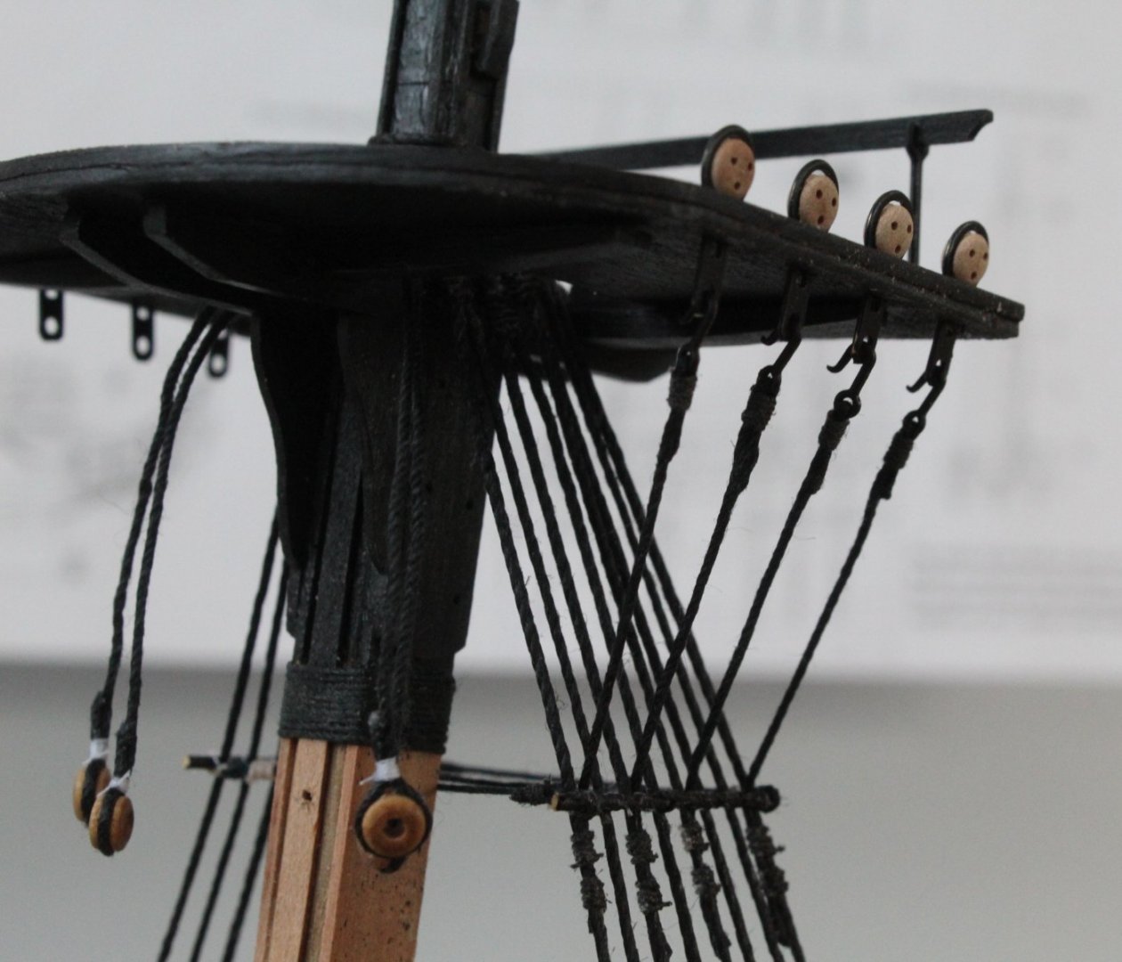
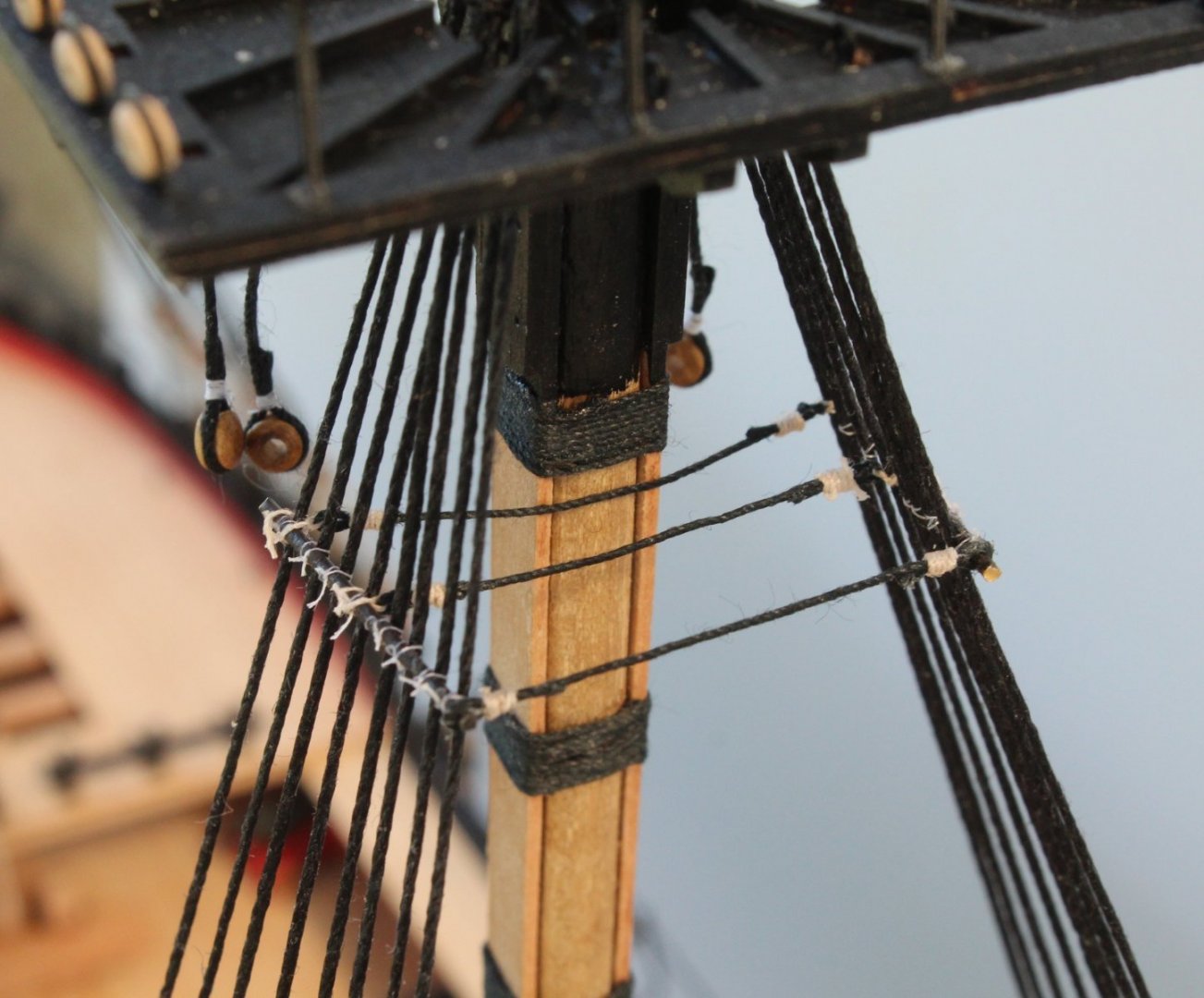
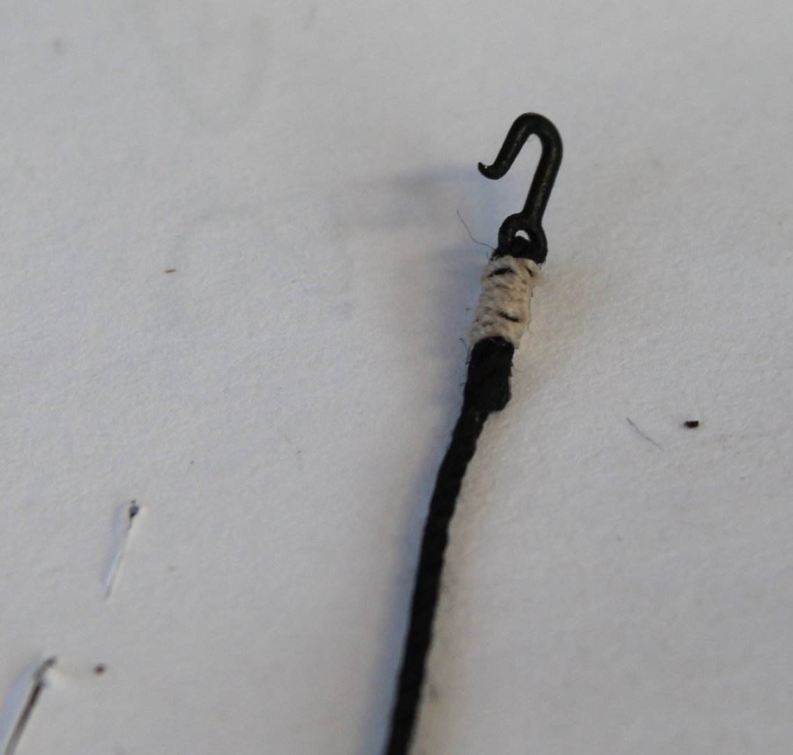
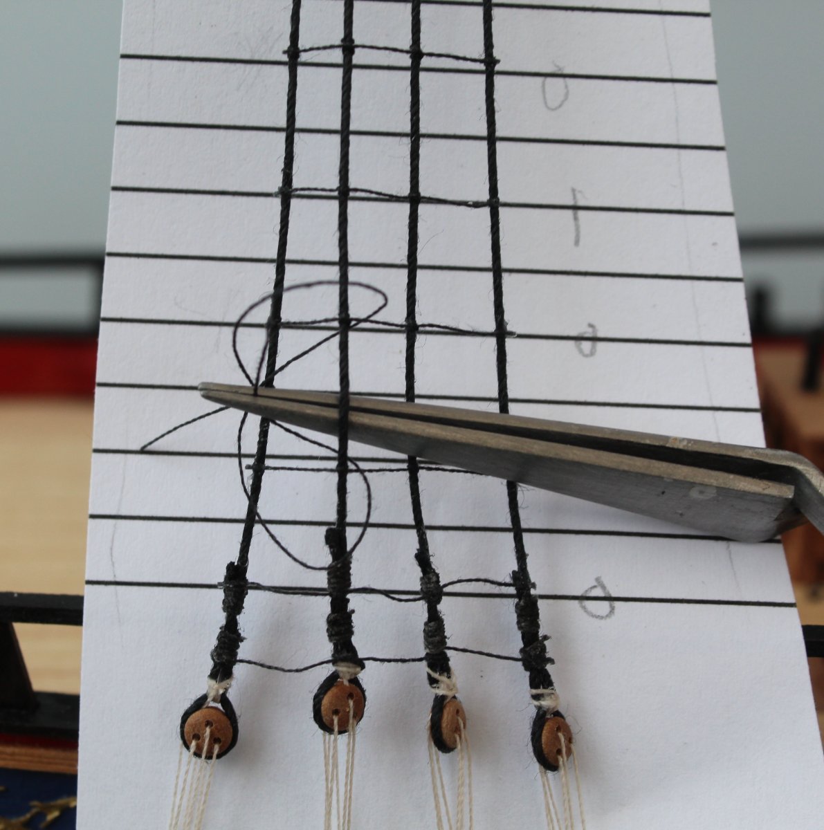
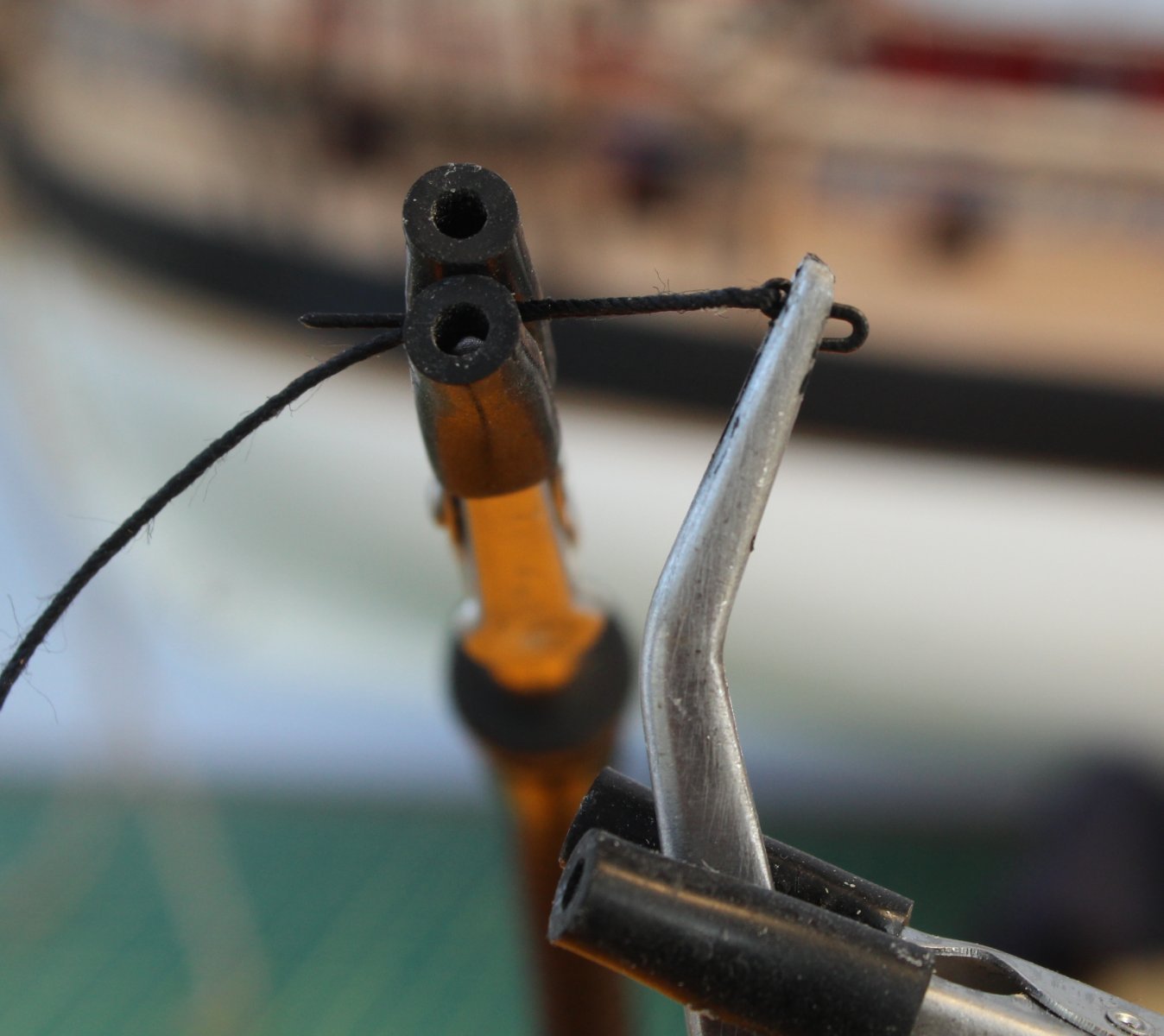
To begin the process I cut a suitable length of ratline thread (approx 8cm for the example below) and I create a clove hitch knot around the first shroud line. This can be seen in the photo below but the knot has not been tightened.
Ensuring I keep as much thread as possible available for the rest of the ratlines the knot is tightened up, checking its position with the template.
Moving on to the second shroud line I form a clove hitch knot. I find I can make the knot much quicker using my reverse action tweezers.

The position of the knot is adjusted to take out the slack, I am almost there in the photo below.
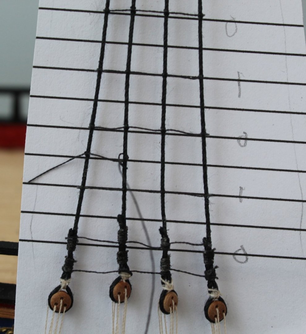
Once I am happy I pull the knot tight.
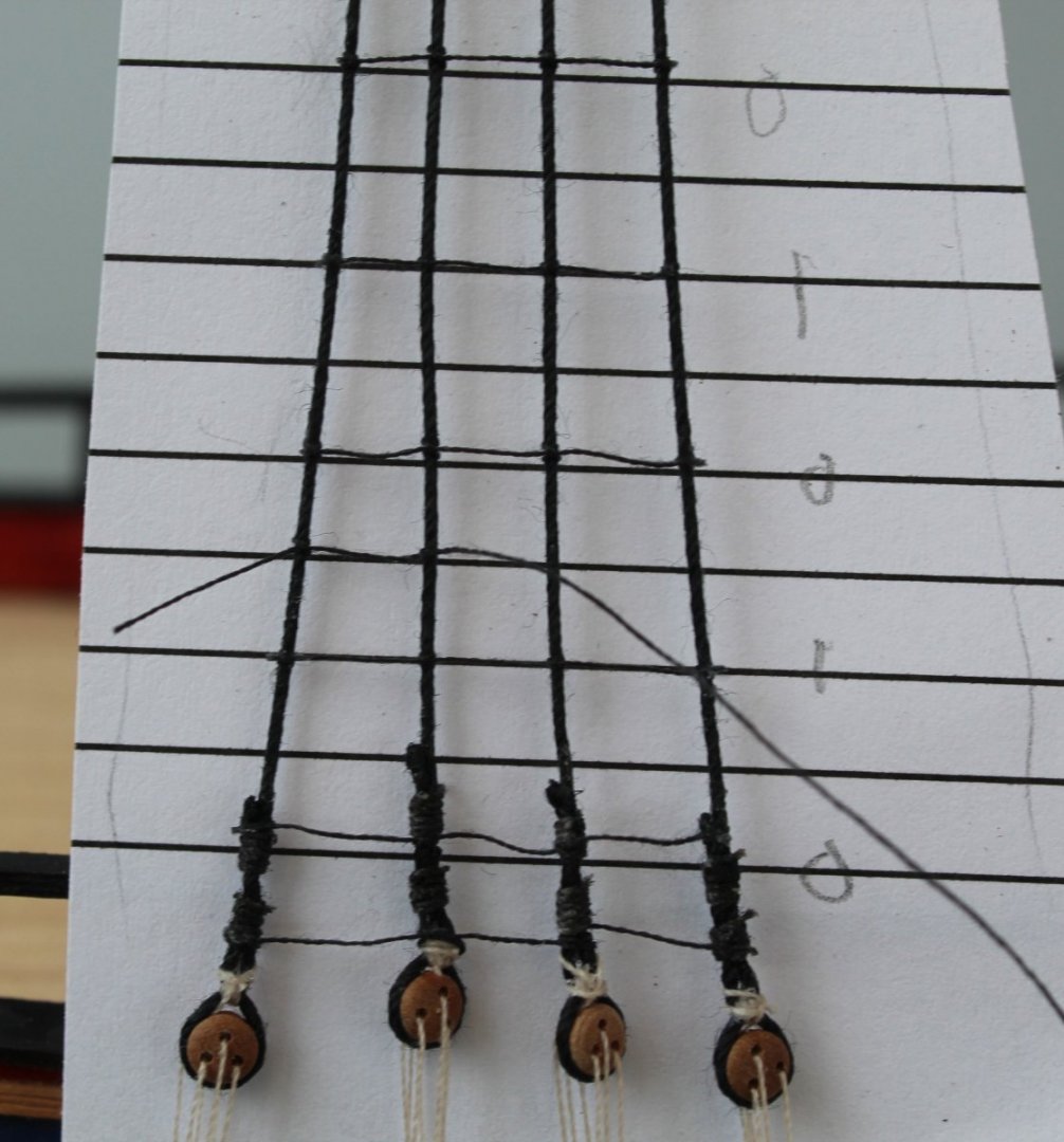
Onward on upward I move to the third shroud line and the first part of the clove hitch knot is formed.
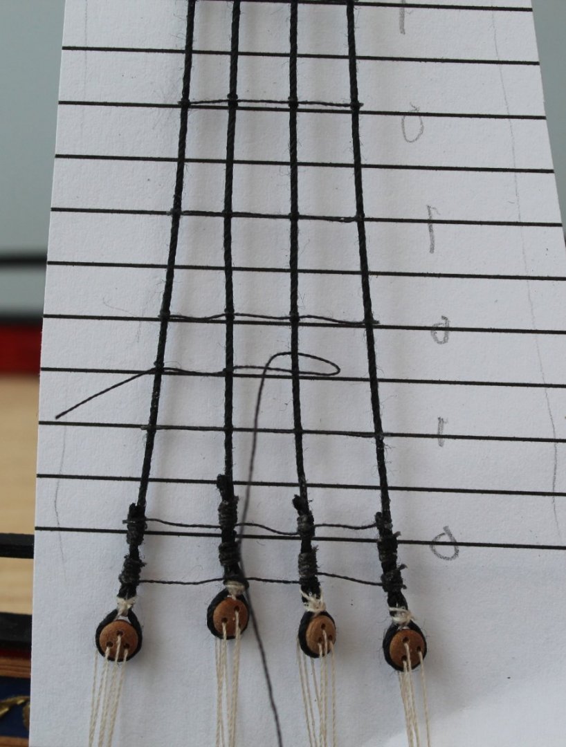
Using the reverse action tweezers the second loop is soon created.
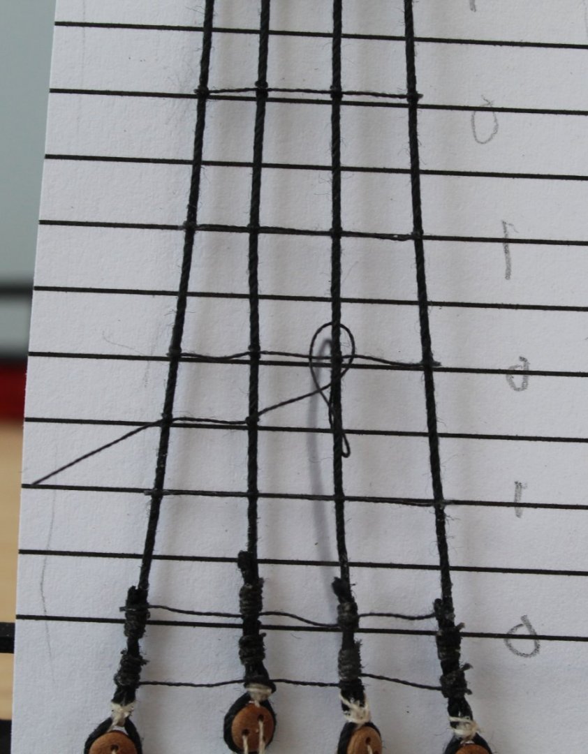
Once the position is adjusted and the slack removed the knot is pulled tight.

On to the final shroud line the clove hitch knot is quickly formed.

Once the slack is taken up the knot is pulled tight. It take me around 3 minutes to add a ratline to the mizzen mast shrouds and around 7 minutes for the main mast.
I use a touch of ca gel to second the knots at each end. I do not apply gel ca to the other knots.
After a few seconds the excess thread can be trimmed. I tend to do a few ratlines at time before I trim the excess.
Once I have completed adding all the ratlines I will check and adjust the positions where necessary before I brush on a diluted pva solution over all the shrouds and ratlines.
- GrandpaPhil, DanB, DocRob and 10 others
-
 13
13
-
-
-
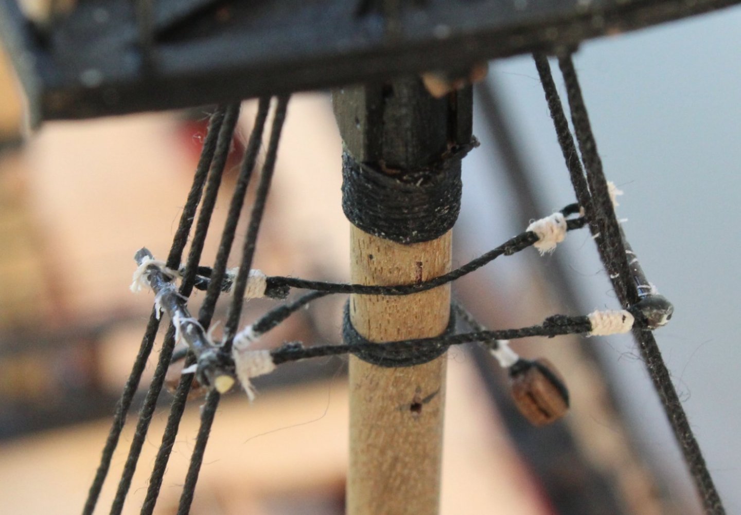
Ratlines - The never ending saga of clove hitch knots.
Work continues with adding the ratlines, each ratline takes me between 5 to 10 minutes to complete.
Yesterday I completed work on the starboard side foremast. There are one of two ratlines I could have done better, but overall I like how they have turned out.
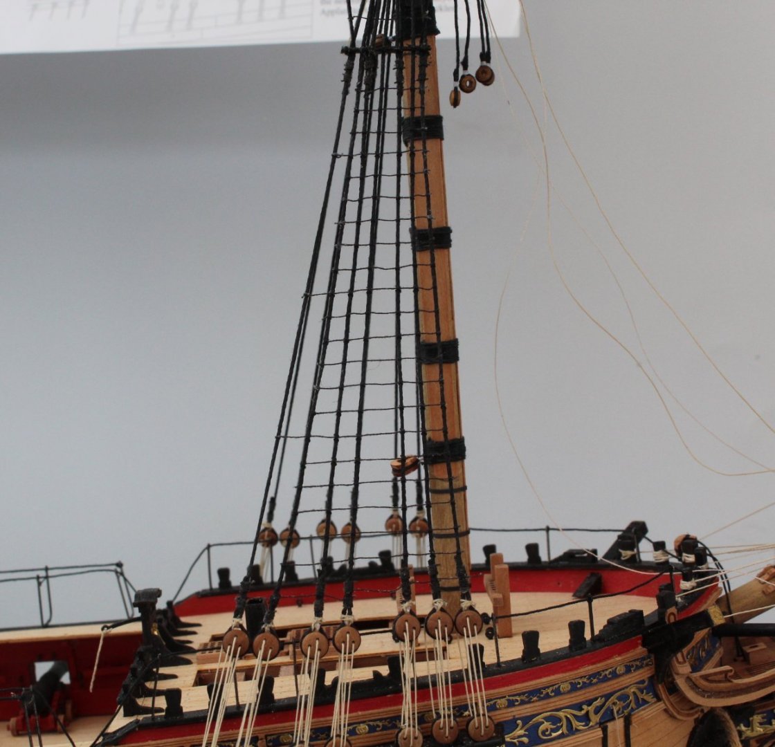
In the picture below I should have added one more ratline just below the catharpin rod. The sailors on this ship will there earn their daily tot of rum when climbing up and over the rod on to the futtock stave ratlines.
This morning I have been working on the main mast starboard shrouds. Again there are 2 or 3 which I could redo but overall they do not look too bad. I am a little bit concerned that I will not have enough ratline thread left to complete the process, especially when I start work on the top mast ratlines. I'm trying not to be too wasteful so fingers crossed.
-
27 minutes ago, Vane said:
Just got back from the harbour for some inspiration for future builds.... USS Kearsage 1993... Waspclass... what a beast!
I should visit the National Museum of the Royal Navy - Hartlepool for inspiration which is about a 90 minute drive. The HMS Trincomalee is berthed there which is one of the two surviving British Frigates of her era. I have been a couple of times and really helps with get an good idea of what these ships were like.
- chris watton, Vane and coxswain
-
3
-
-
-
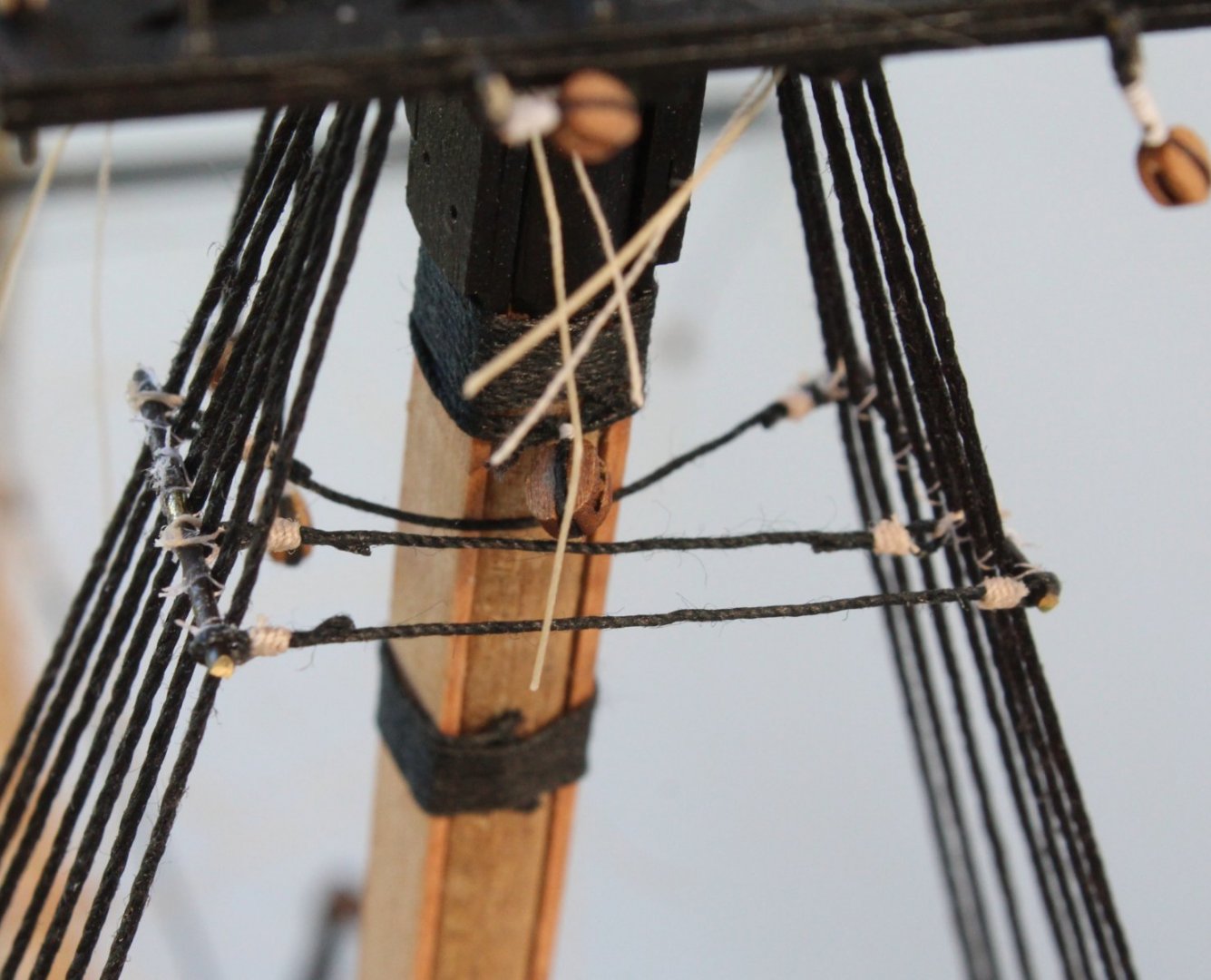
Ratlines - The beginning
Over the next couple of weeks I will mostly be tying clove hitch knots😆
As per my last post I have opted for a 5mm spacing between the ratlines to replicate a 13" spacing.
(13" * 25.4 / 64 = 5.15mm)
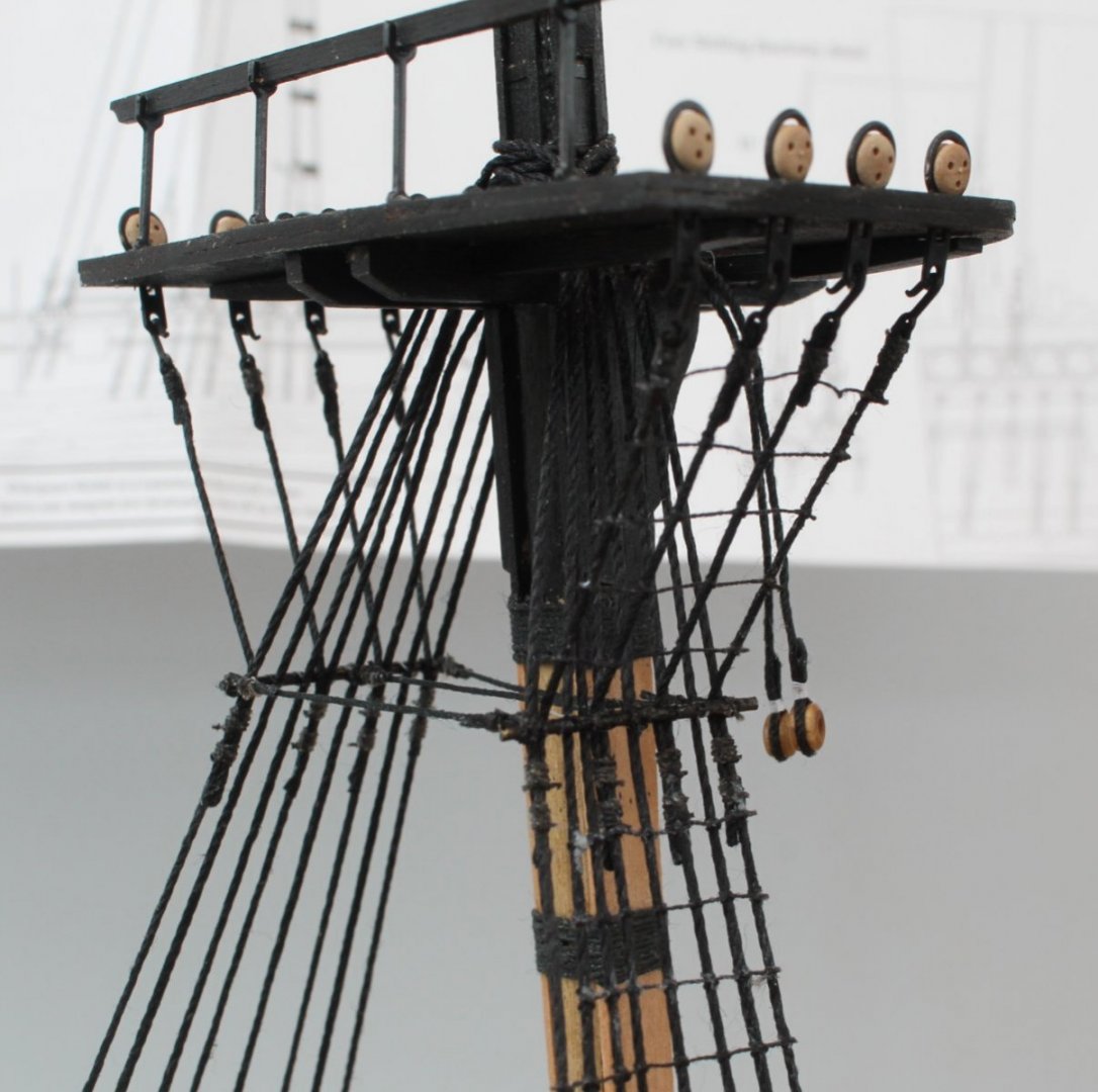
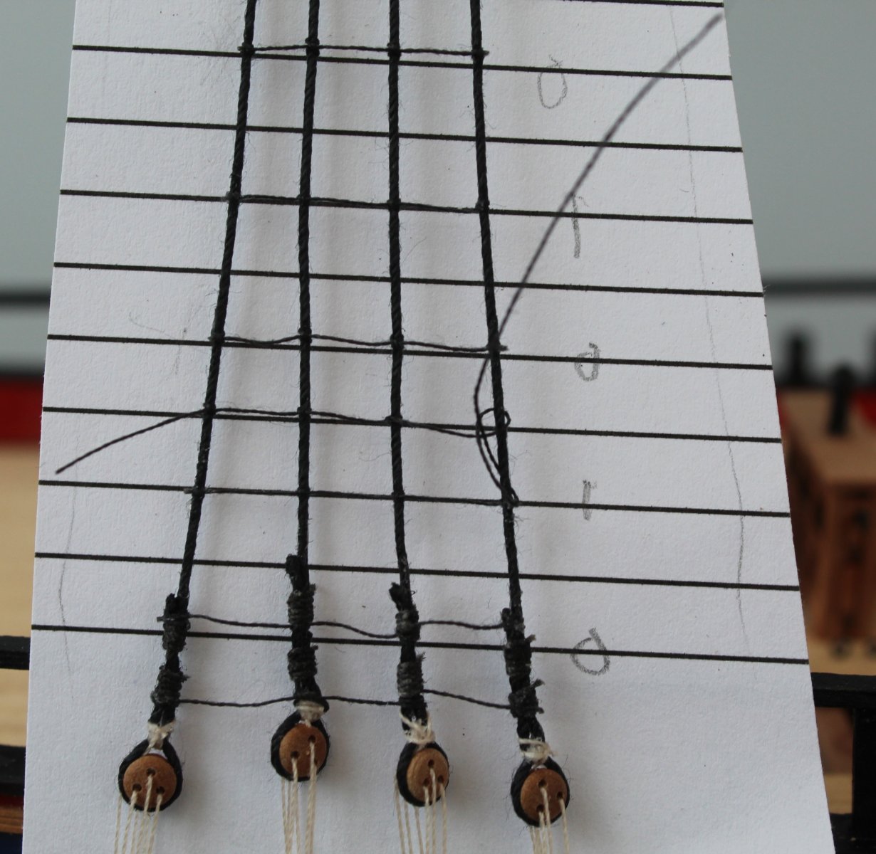
The lowest ratline is tied to all the shroud lines. The next 5 ratlines are not required for the outer stern side shroud. The pattern of full width ratlines spaced between 5 shorter length ratlines repeats over the full length. I have indicated this on my spacing template where X indicates the full length ratlines.
It took me a few minutes before I found my clove hitch knots mojo again but once I got back into the swing of tying them it does not take me too long to add each ratline. In the two pictures below I have added all the full width ratlines for the foremast starboard side shrouds. My next update in a few days time will hopefully show the completed ratlines for the foremast, post and starboard.
With reference the photo below I did struggle to get the lowest ratline positioned correctly due to the presence of the shroud seizing's. After two attempts I have decided to accept for the time being. I might change my mind and redo once I have completed adding the rest of the ratlines.
All clove hitches are being lined up with the template, and a final check will be done before I apply some diluted pvc to the completed ratlines / shrouds.
-
-
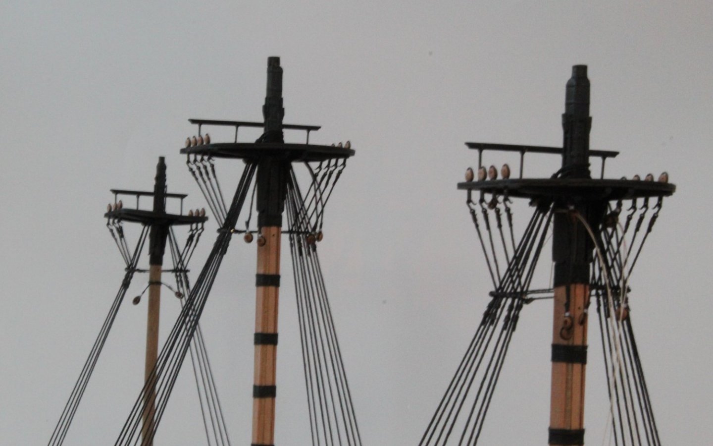
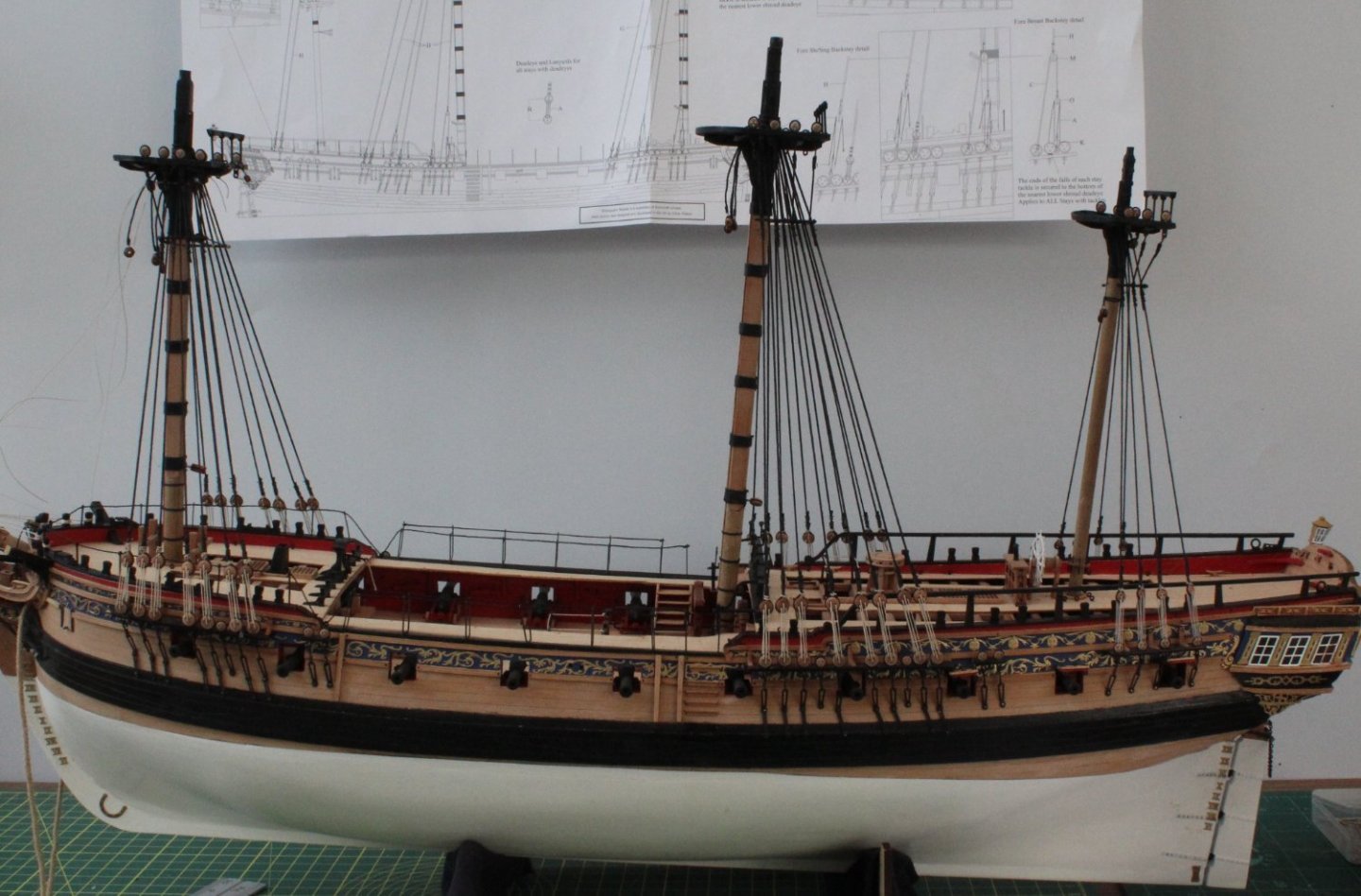
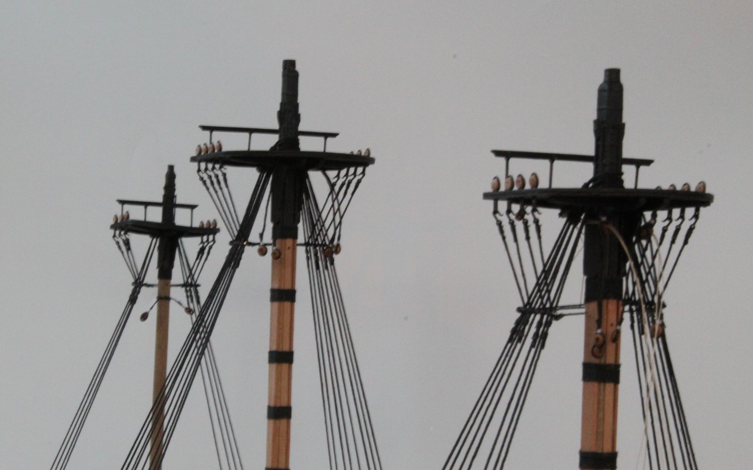
Futtock Staves - Completed
I was able to spend more time than I thought in the shipyard today so I was able to complete adding the futtock staves to the starboard side. Overall I am extremely pleased with how they have turned out.😀
Ratlines to be added next. From a little bit of research I have done the ratlines on HMS Victory were set 13" apart. Adjusting this dimension for 64th scale and converting to metric yields a spacing of approx. 5mm (13" * 25.4 / 64=5.15mm) between ratlines.
A preliminary estimate is there will be around 24 ratlines on the foremast per shroud and plenty of clove hitch knots. In the past I have found adding ratlines relaxing so fingers crossed 🤞it will be the same again for the Sphinx.
I have added a couple of very similar pictures of the completed futtock staves.
- KARAVOKIRIS, mtaylor, DelF and 8 others
-
11
-
-
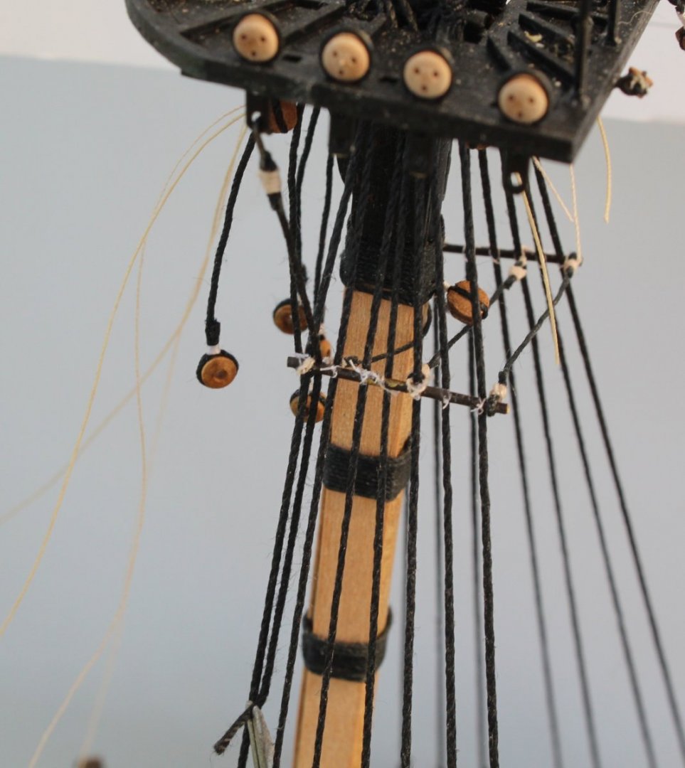
Port Side - Futtock Staves
First job this morning was to add all the futtock strop hooks to the futtock staves (100mm x 0.75mm black thread). In total I seized 22 futtock strop hooks to 22 threads. It took me a couple of hours to complete. It was then a case adding each futtock stave to their respective shrouds, passing them over and behind the catharpins. It was another 2 hours work to complete the port side today and I plan to start work on the starboard side tomorrow, but my time will be limited due to grandparent duties.
The photo below shows the current build status.
Foremast Futtock Staves
Mainmast Futtock Staves
Mizzenmast Futtock Staves
There is some debate if the mizzen mast was fitted with catharpins on the actual ships of this period. As they included on the prototype build and shown on the rigging plans I went ahead and added them. I may regret this later on as it might hinder the fitting and rigging of the Gaff.
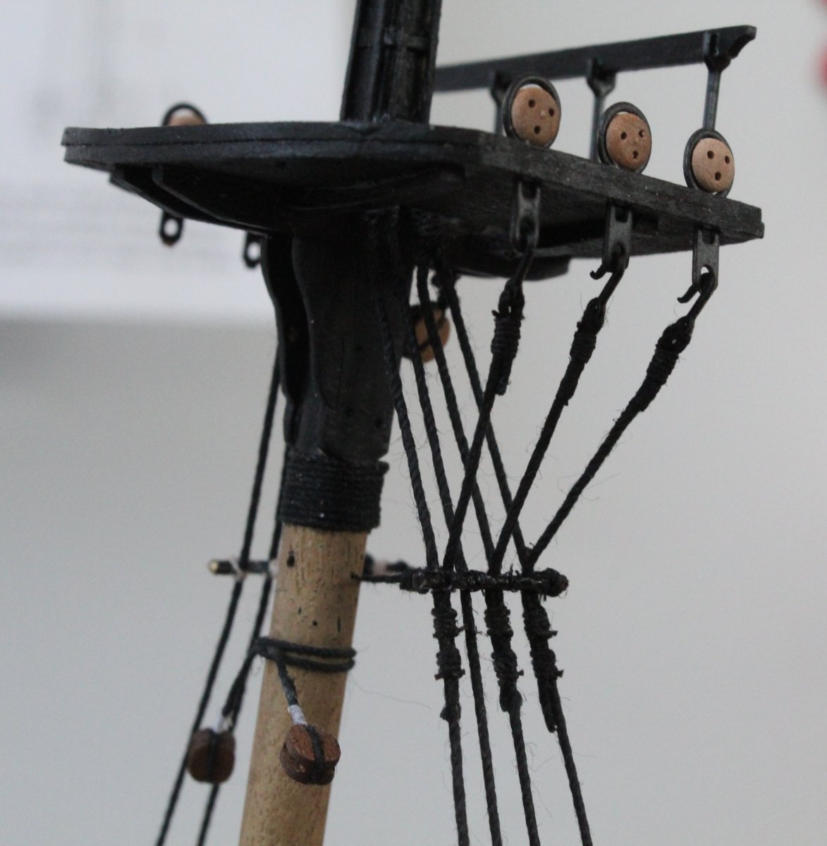
With the futtock stave passed behind the catharpin it is held in place with a pair of reverse action tweezers, as shown in the photo below. I then added two seizing's to secure the futtock stave to the shroud. Once complete the excess thread was trimmed.
Once all the futtock staves were installed I applied some Indian ink to the natural thread.

-
2 hours ago, Blue Ensign said:
Hi Glenn, re the Mizen Catharpins:
Lees mentions use of these on the Mizen, but they are not included on the rigging plan for Pandora (AotS) nor do they appear in Steel's rigging tables for vessels rated 20 -24 guns. If you decide to keep them consideration needs to be given how they may impact when it comes to fitting and rigging the Gaff.
B.E.
Hello BE
Many thanks for your observations. I have no knowledge of what was actually fitted to the real ships. I just follow the plans provided with the kits I buy. I also look at all the different build logs on MSW as well.
I have noted that on the prototype Sphinx built by @James H the catharpins were added to the mizzen mast. They are also shown on the rigging plans provided by @chris watton which is why I added them. I am sure adding the Gaff will present me with plenty of problems and headaches with or without the catharpins and futtock staves.
You build work is truly amazing and I wish I had the skill set and patience to emulate your very high standards of workmanship.
Thanks
Glenn
- mtaylor, Blue Ensign and Dave_E
-
3
-
This post covers the completion of the catharpins and the start adding the futtock staves.
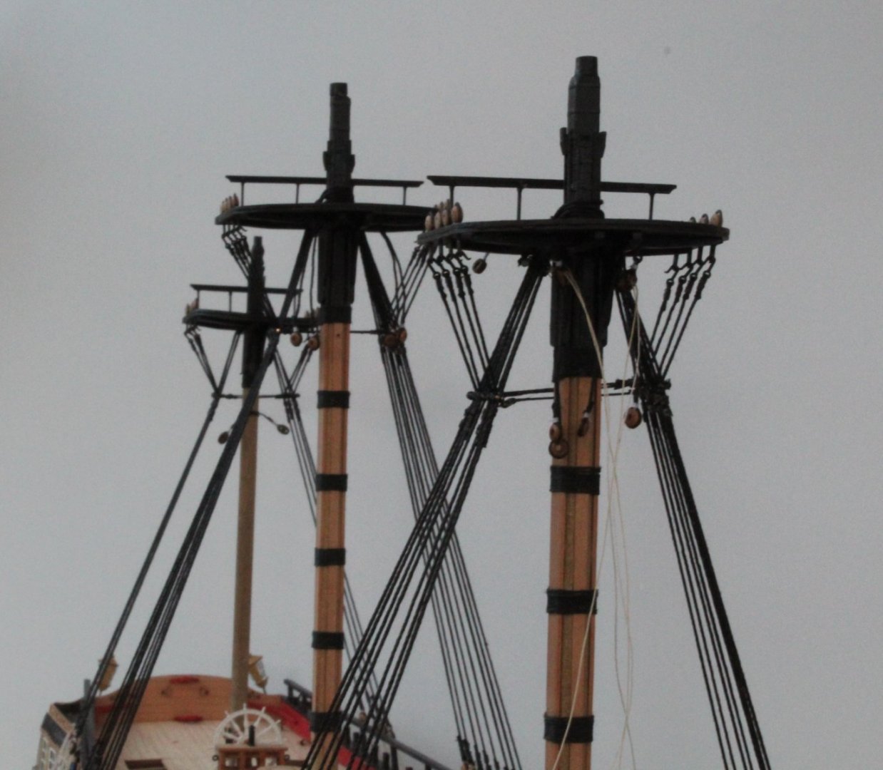
Catharpins - Completed
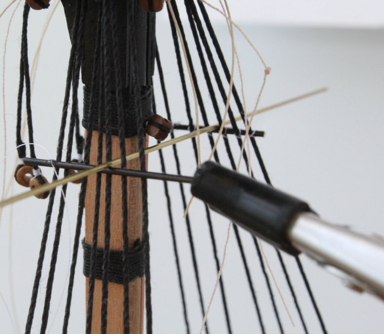
I have now completed the installation of the catharpins for the fore, main and mizzen masts. I am really happy with how these have turned out and the end result far exceeded my expectations which were based on my efforts on previous builds. As stated in a previous post I tried to replicated the method illustrated in Lennarth's Petersson's book "Rigging Period Ship Models". I was not looking forward to this task but now I seemed to have found a method which is relatively easy to implement it turned out to be not so bad.
Main Mast Catharpins
Mizzen Mast Catharpins
Fore Mast Catharpins
Futtock Staves
There are 22 futtock staves to add, 8 for the foremast, 8 for the main mast and 6 for the mizzen mast. I have collected 22 x futtock strop hooks and I have also cut 22 x 100mm lengths of 0.75mm black thread. I have started to add the futtock stave thread to their respective strop hooks. The picture below show the first four futtock staves for the foremast which are now ready to be seized to the strop hooks.
Using the quad hands the first futtock stave is held in place ready for the seizing to be added.

It did not take long to add the seizing using 0.1mm natural thread. I used 12 half hitches for the seizing with 6 half hitches on the bottom and 6 half hitches on the top. The completed part is shown below.
The final picture of this post shows the first futtock stave in place and it is ready to be seized to the shroud. The futtock stave has been passed over and behind the catharpin and then held in place using my reverse action tweezers. It should be a relatively easy task to secure the futtock stave to the shroud. I plan to make all 22 of the futtock staves before I start adding them to the shrouds. After that it will be time to add the ratlines.
- chris watton, DelF, JeffT and 7 others
-
10
-
-
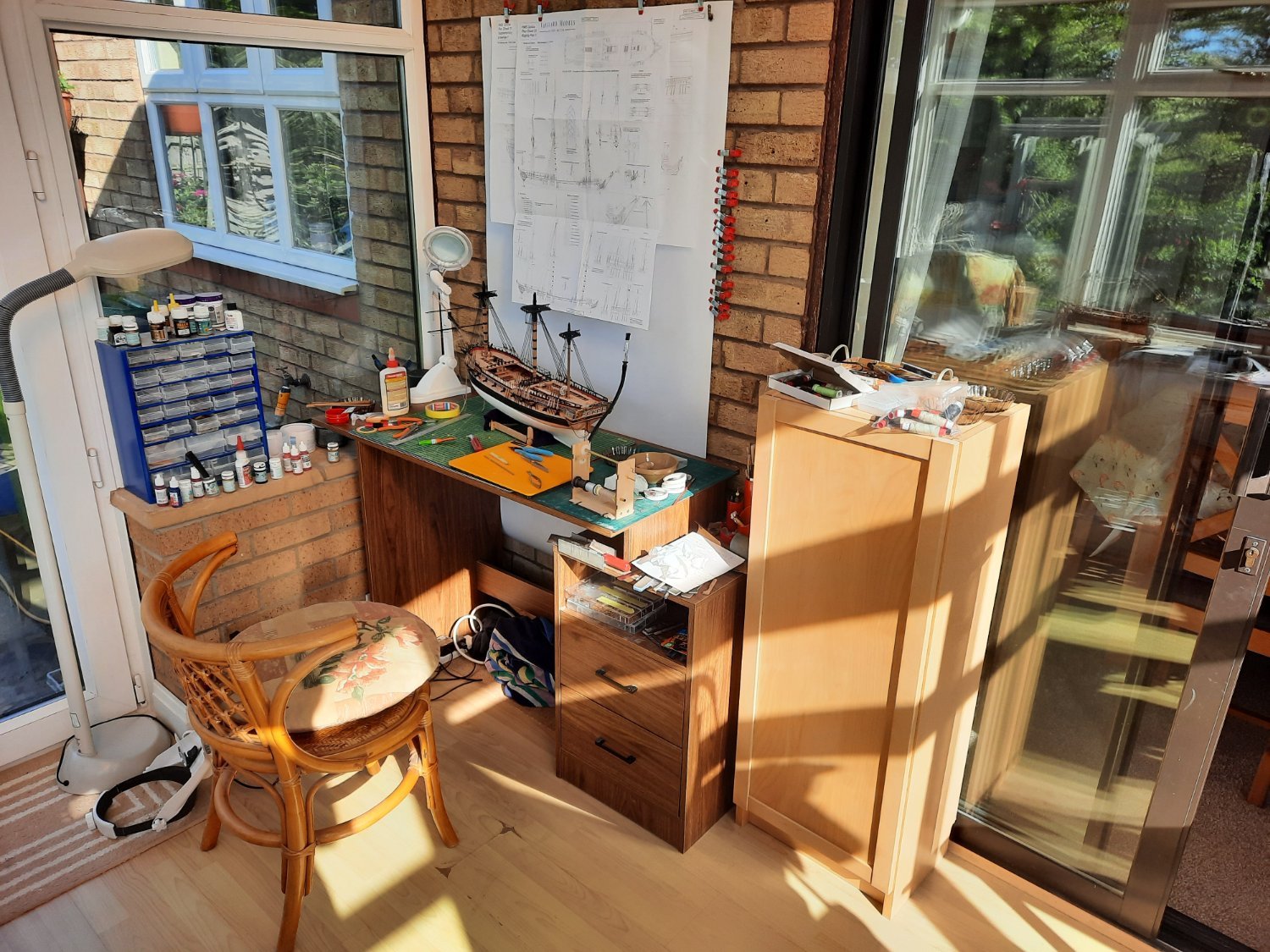
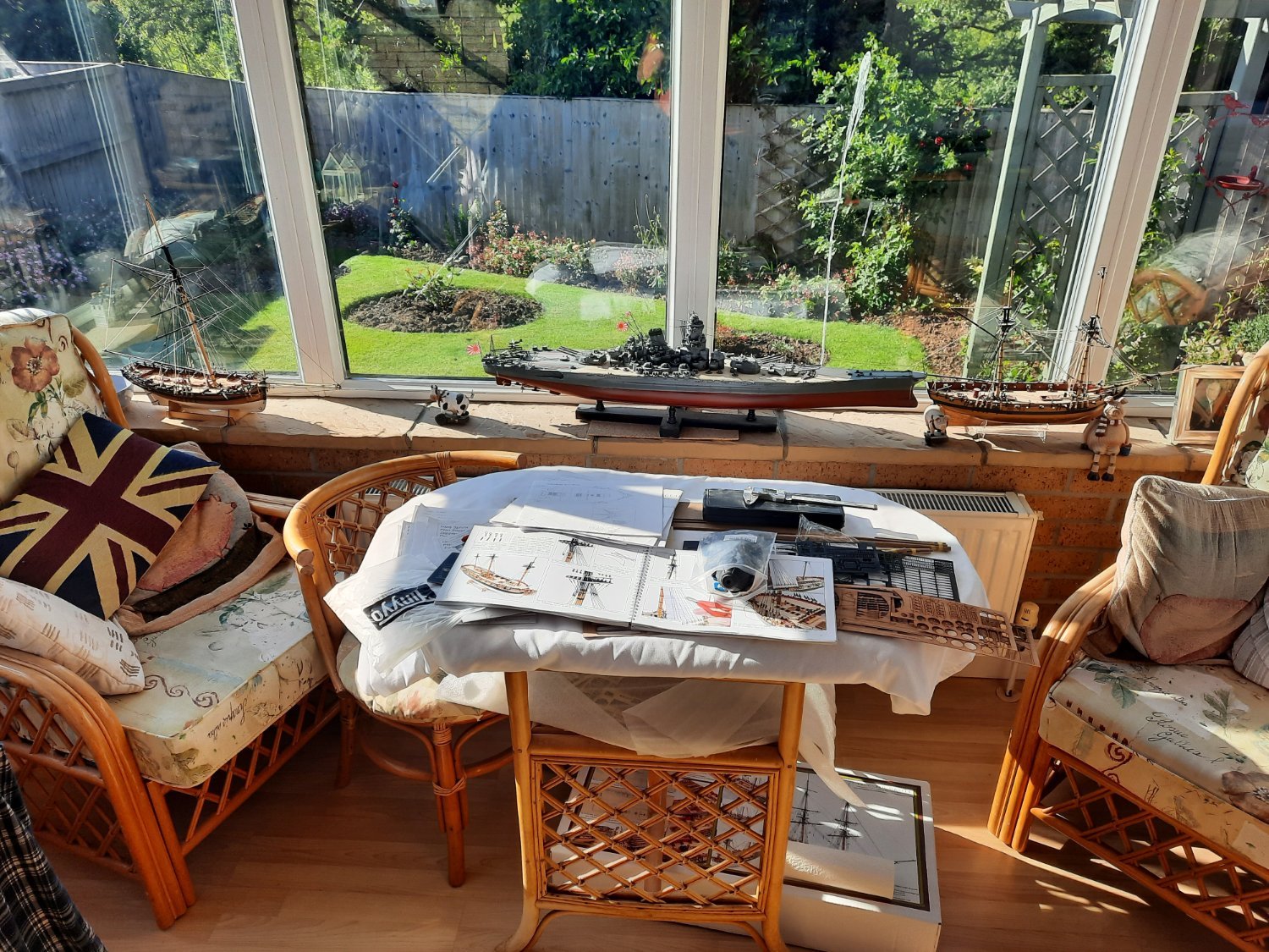
Another impressive workspace. I would like to refit my garage out for this hobby but instead I'm getting the bathroom, ensuite and downstairs cloakroom refurbished.
- DelF and chris watton
-
1
-
 1
1
-
-
Looks like you are building an exceptional model.
- Keith Black, DocRob and chris watton
-
2
-
1
-
20 minutes ago, James H said:
This is coming along very nicely indeed!
Thank you Jim. I am very pleased with how the lower foremast catharpins have turned out.
- chris watton, mtaylor and Dave_E
-
3
-
Foremast Catharpins - Completed
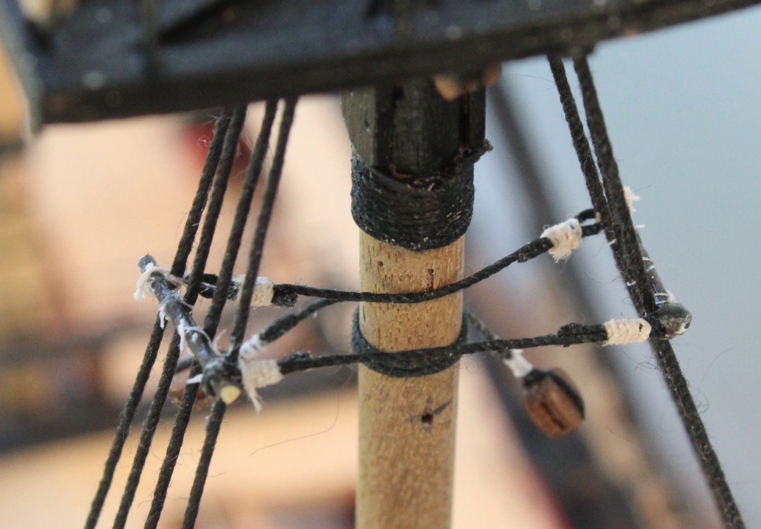
After the false start detailed in my last post I was able to remove the port side brass rod without any problem. It was then a simple case setting the brass rod to the same level as the starboard side. With the port side brass rod held in the required position it is ready to be secured to the shrouds. This can be seen in the photo below where I have already secured it to the furthermost shroud line, using fly tying thread.
It did not take long to complete securing the brass rod to the shrouds and double checking it is at the same level of the starboard side.
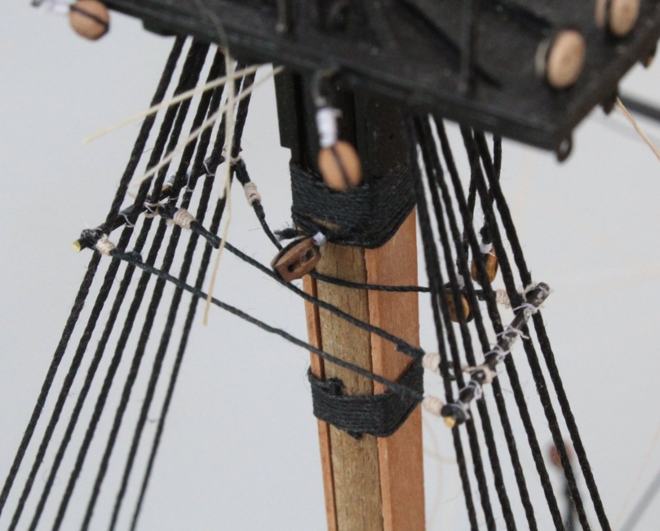
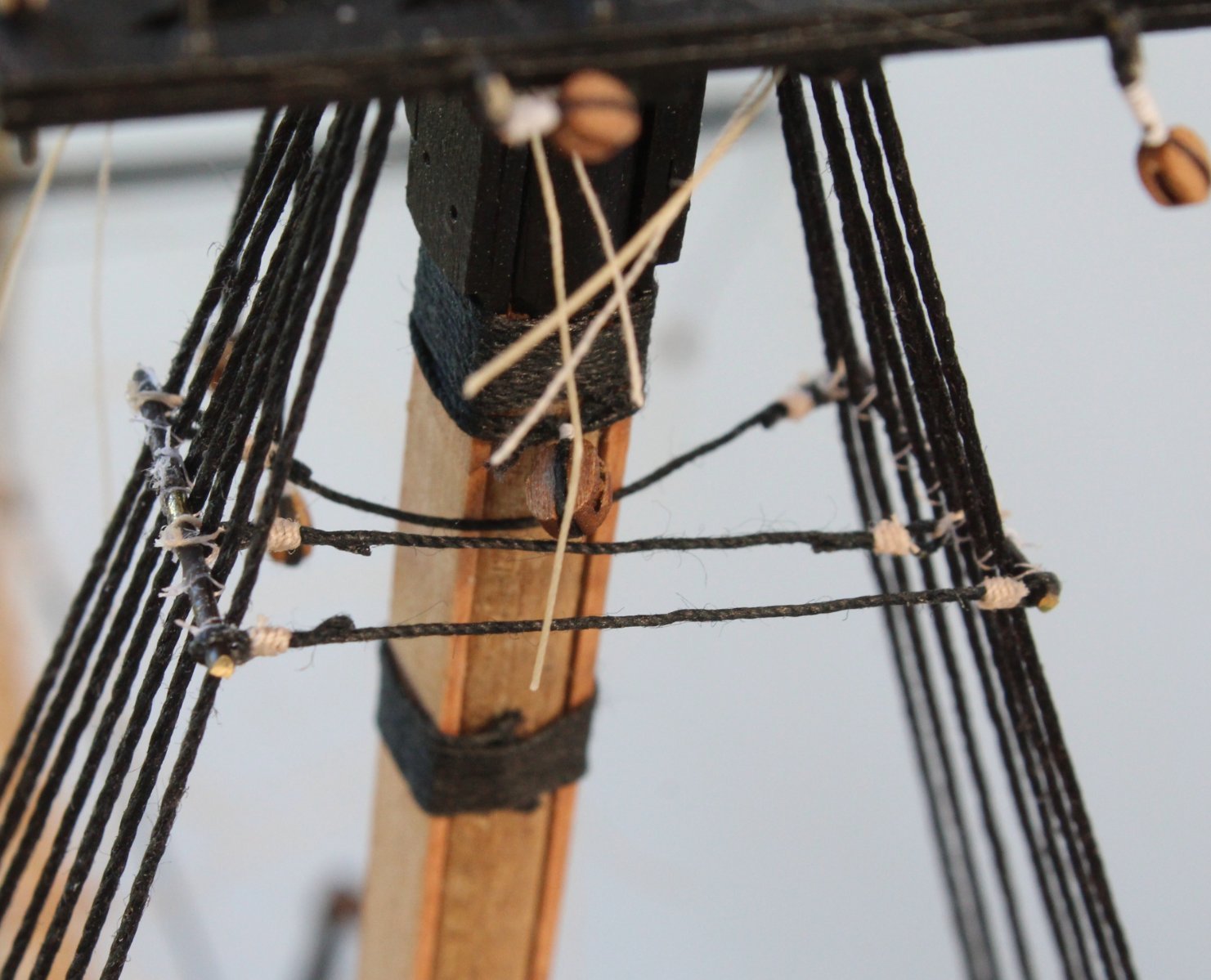
I was unsure which method to use for the links between the shrouds. I opted to try the method outlined in Lennarth Petersson's book entitled Rigging Period Ships, as shown in the picture below.
I used a length of dowel to workout the distance between the shrouds at each point and made up the cross threads. I tried to make them a tad shorter than required.
The first cross thread was a tad too long to be rigged as shown Lennarth's book but it slid over the ends of the brass rod and was a perfect fit.
The remaining two cross threads were fitted as per the method shown in Lennarth's book. The middle one took two attempts to get fixed but it ended up being a good fit. I had to remake the final cross thread as the first one was a bit too long. There is quite a curve for the furthermost cross thread around the foremast, which is evident in the photo below. I have never done catharpins this well before so I am very pleased with how they look. All that is left to done is apply some Indian ink to the thread and touch up the brass rod, as necessary.
- chris watton, KARAVOKIRIS, Dave_E and 6 others
-
9
-
-
-


HMS Speedy by Vane - Vanguard Models - Scale 1:64 - Master Shipwright (limited edition)
in - Kit build logs for subjects built from 1751 - 1800
Posted
Nicely done