HOLIDAY DONATION DRIVE - SUPPORT MSW - DO YOUR PART TO KEEP THIS GREAT FORUM GOING! (Only 20 donations so far - C'mon guys!)
×

archjofo
-
Posts
1,495 -
Joined
-
Last visited
Content Type
Profiles
Forums
Gallery
Events
Everything posted by archjofo
-
 @dvm27 Hello Greg, maybe this rather clumsy drawing can explain it further.
.thumb.jpg.047496266c01161f7027edc19af86363.jpg)
-
@jdbondy Hello, for the double strop I use a rope that has already been served, which is formed into a loop. The place where the loop is glued together comes under the round seizing. If I didn't explain it clearly, just ask again.
-
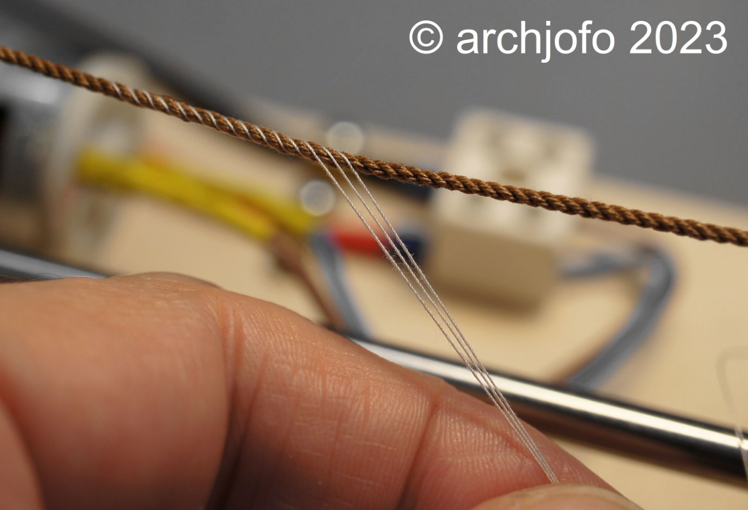
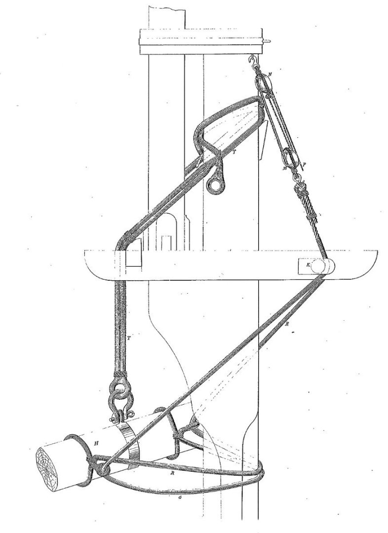
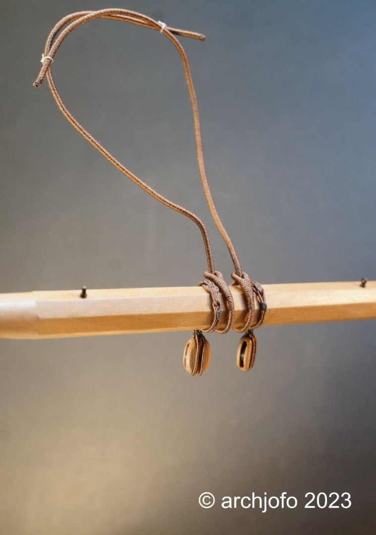
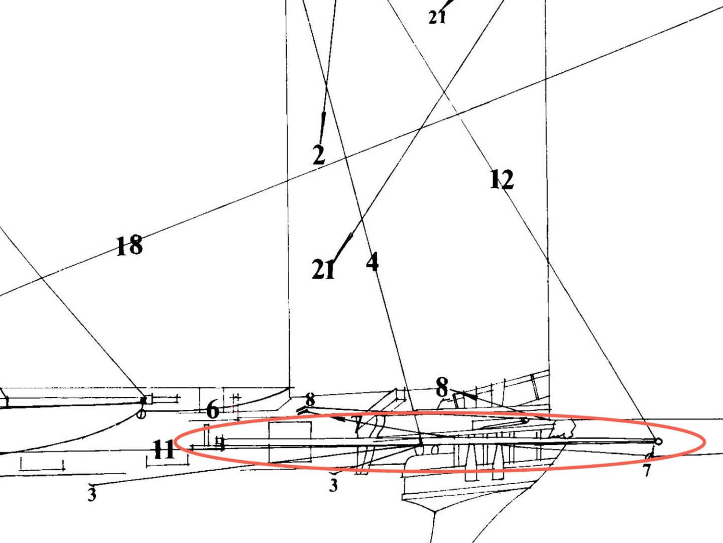
Continuation: Equipment of the lower yards - Quarter blocks / Slings - Poulies d'ecoute et de cargue-point / suspentes In the meantime, the quarter blocks of the main yard have been fastened at the appropriate positions by means of rose lashing. I continued with the slings. These strong ropes with ø 43 mm (0,9 mm in 1:48 ) are completely served. There are two of these slings per yard, each with a spliced eye at the end. In preparation for serving these ropes, they were wormed in advance. As described some time ago, the pre-wormed model ropes simply look more realistic. Here is a picture of the current condition of the rigging elements on the main yard: Next I will make the truss pendants and jackstays and mount them to the yard. The following picture from the Atlas du Génie maritime shows, among other things, the truss pendants as it was most certainly used on the La Créole, which is also the case on the original model. Accordingly, I have provided the necessary sheaves when making the longitudinal salings. The slings shown in this picture do not correspond to those of the La Créole. Source: Extract from Atlas du Génie maritime, annexe No. 1, Pl. 23 To be continued ...

-
@Mic_Nao @jfhealey @Tigersteve @dvm27 @garyshipwright Hello, Thank you very much for your attention and the nice comments. And also thanks to the others for the LIKES. @dvm27 Yes I have a simple method. I use a fine brass wire 0.2 mm. Instead of a rope, I make a temporary strop with this wire around the block and yard. Then I straighten the wire and measure the length. I hope that I have expressed that in an understandable way. @garyshipwright I bought it here in Germany in an online shop. There are many things for model building. This LINK leads to this shop.
-
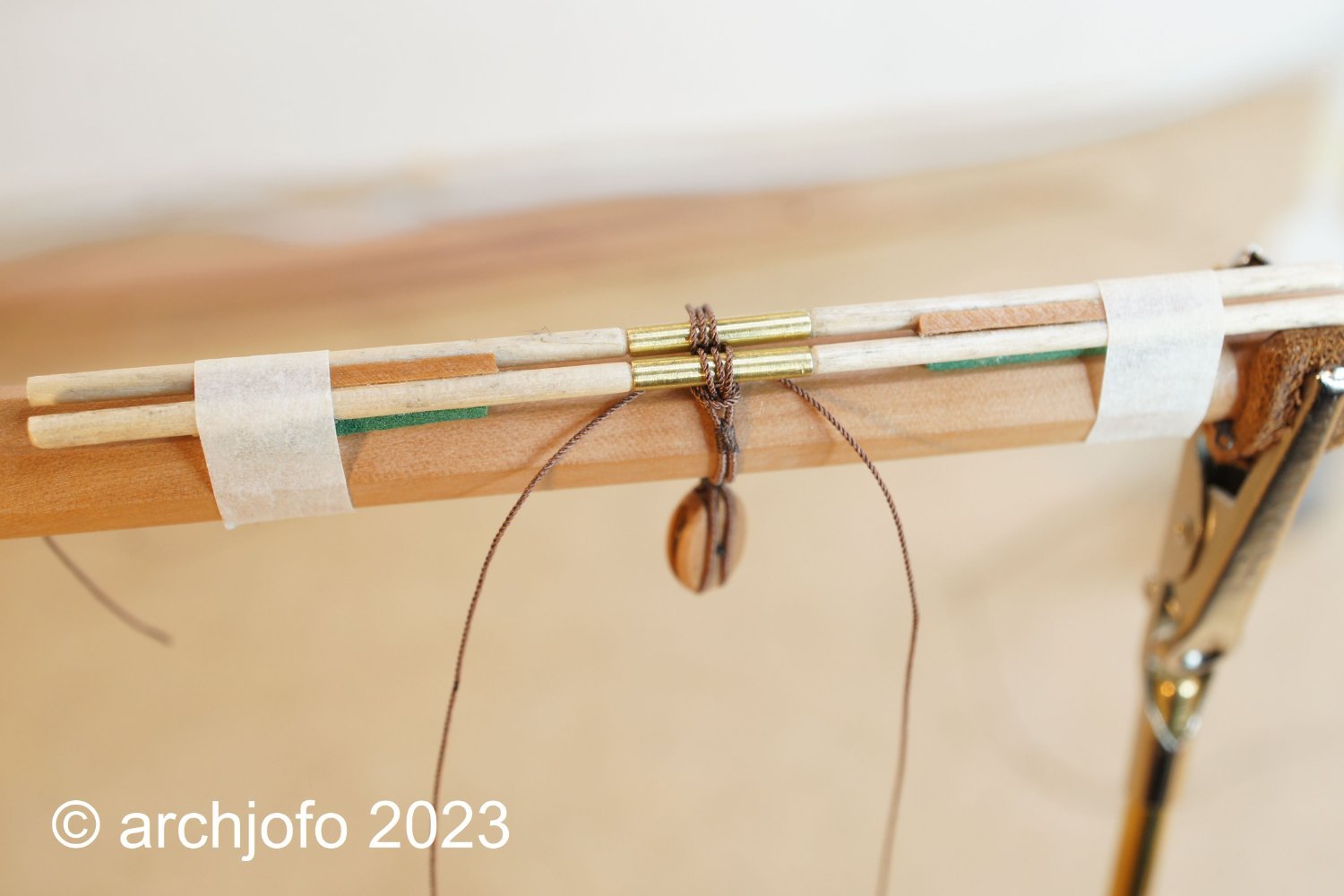
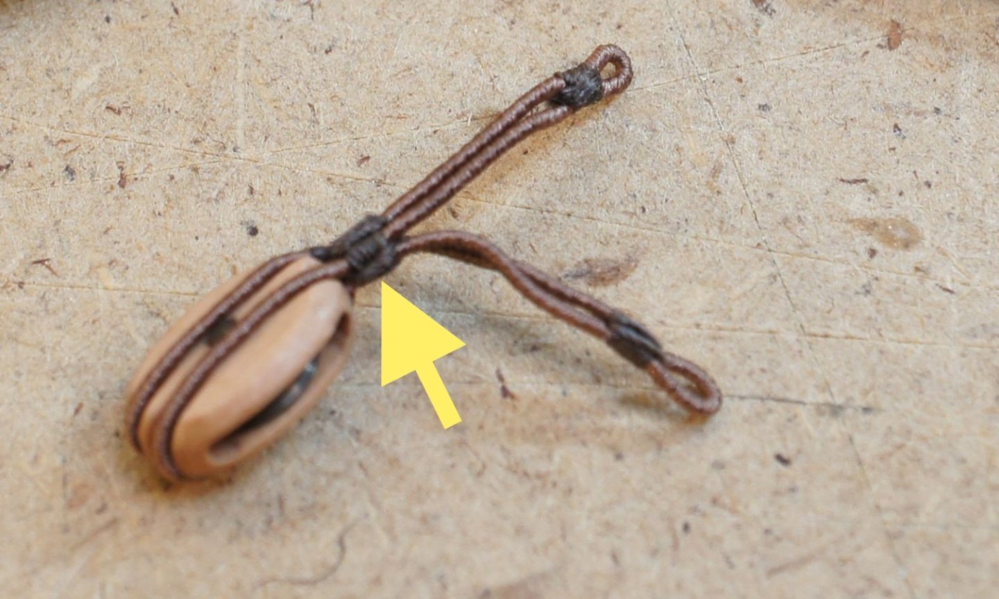
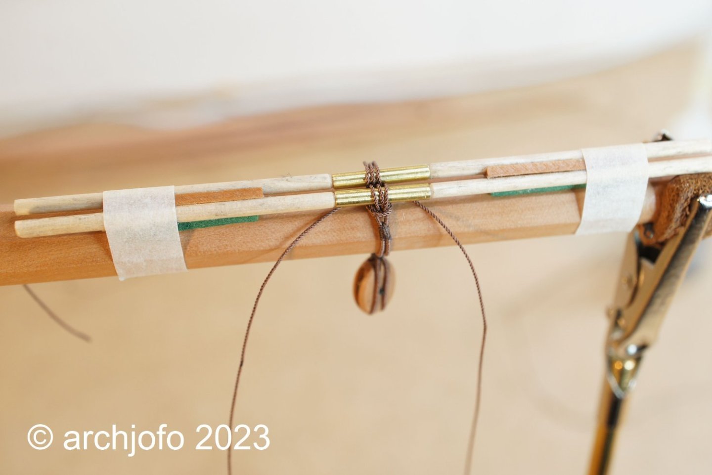
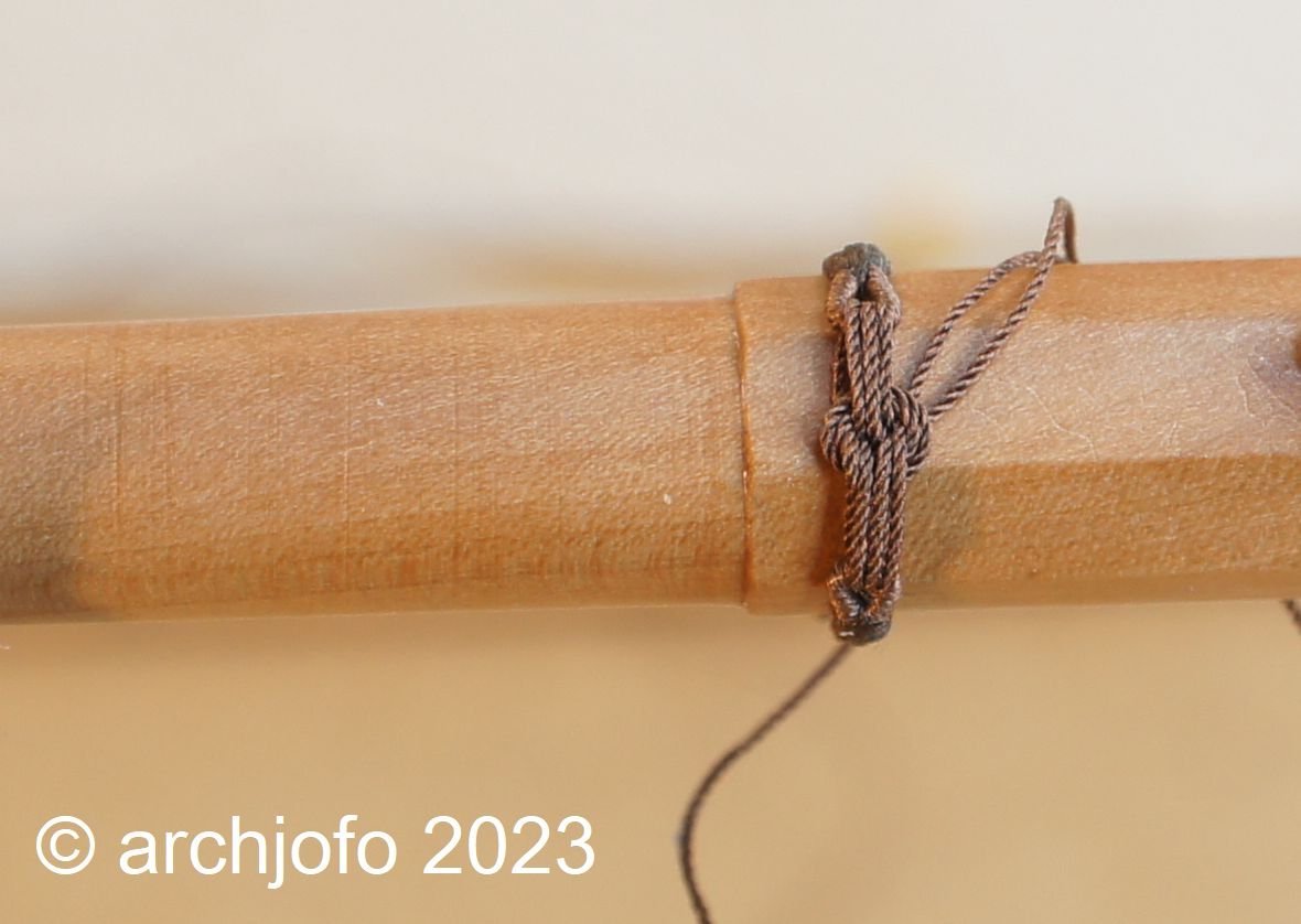
Continuation: Equipment of the yards - Quarter blocks of the lower yards - Poulies d'ecoute et de cargue-point The quarter blocks of the lower yards were equipped with double strops and lashed at the appropriate positions with rose lashings. Other model building colleagues have successfully demonstrated that it is even possible to depict a rose lashing on a scale of 1:75 and smaller. It should be all the easier to do on a scale of 1:48. In this context, I remembered Frank's contribution "Making rose lashings" (LINK). In it he explained very clearly and comprehensibly with text and pictures the step-by-step process of how to make a rose lashing. The tool he made from toothpicks makes the process a whole lot easier. Thanks to these excellent instructions, I was able to try a rose lashing on a test yard relatively quickly in advance, after I had modified Frank's tool a bit. In this respect, I can simply pull it apart through the sockets and don't have to snap through the toothpicks later. By temporarily gluing the aid to the yard, the required cross lays can be easily produced. I like the result. So I will then do it at the appropriate positions. I still have to think about the execution of the knot. Sequel follows …
-
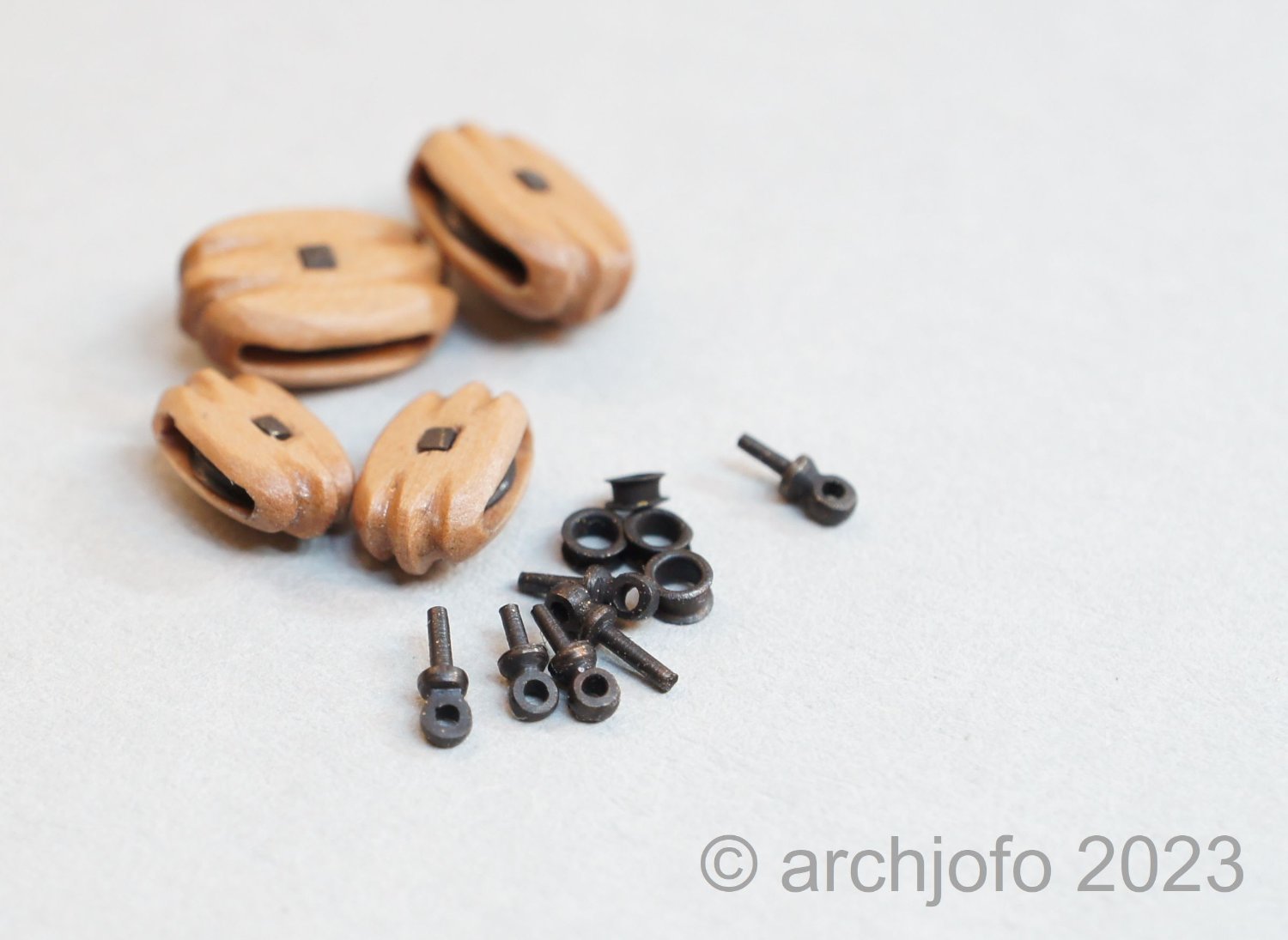
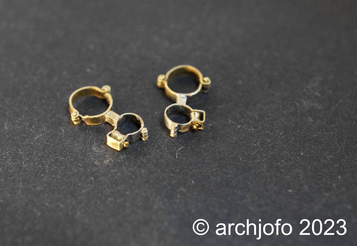
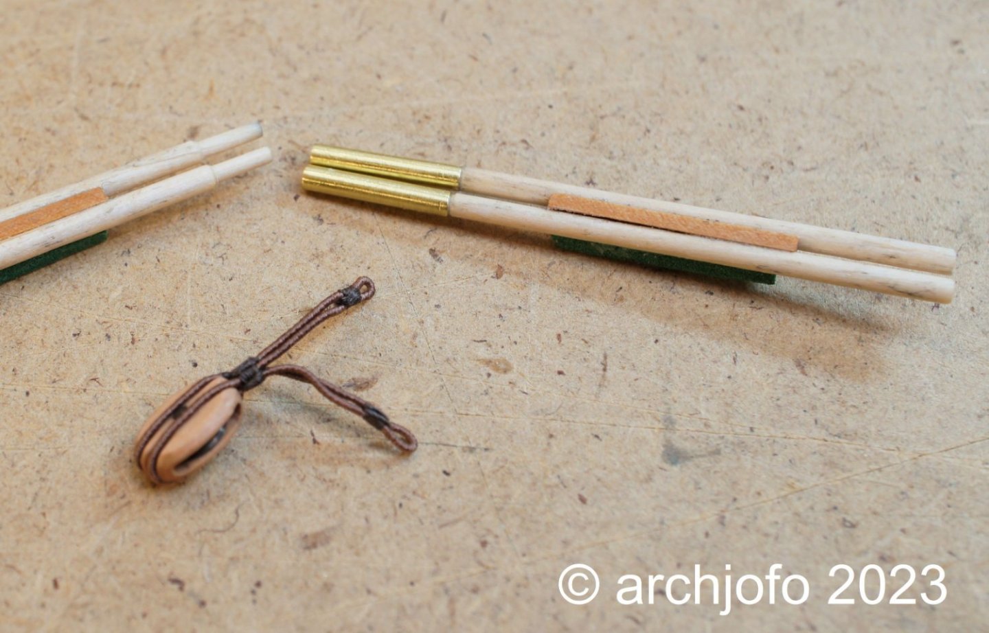
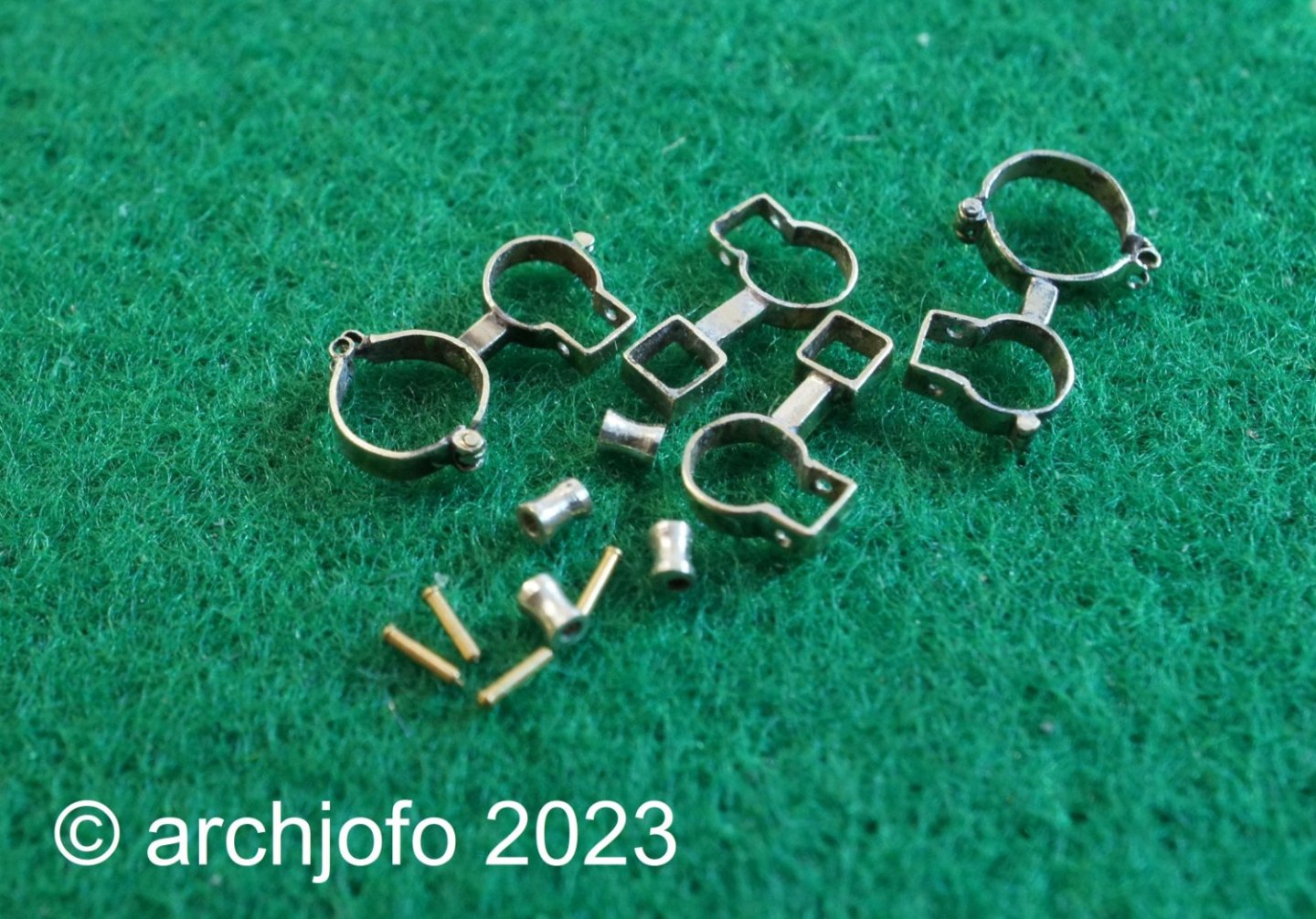
Continuation: Equipment of the yards - Quarter blocks of the lower yards - Poulies d'ecoute et de cargue-point As already announced, here are the smaller quarter blocks for the fore yard. In addition to the fully assembled quarter blocks, you can also see some eyebolts and thimbles for the jackstays here on this picture.

-
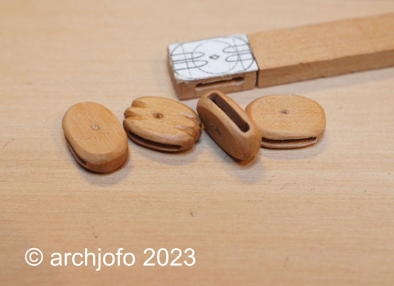
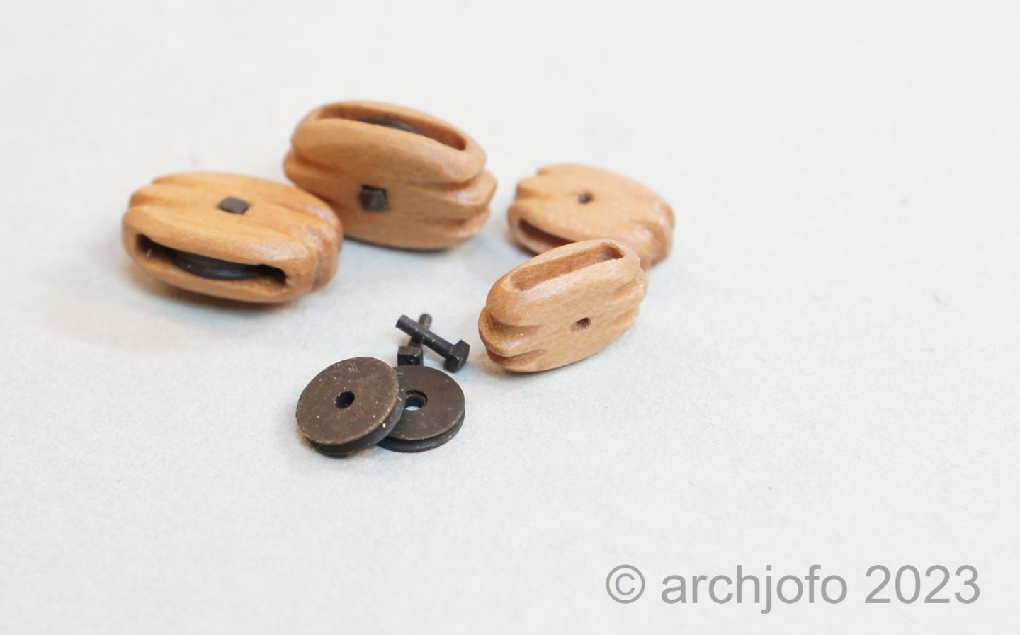
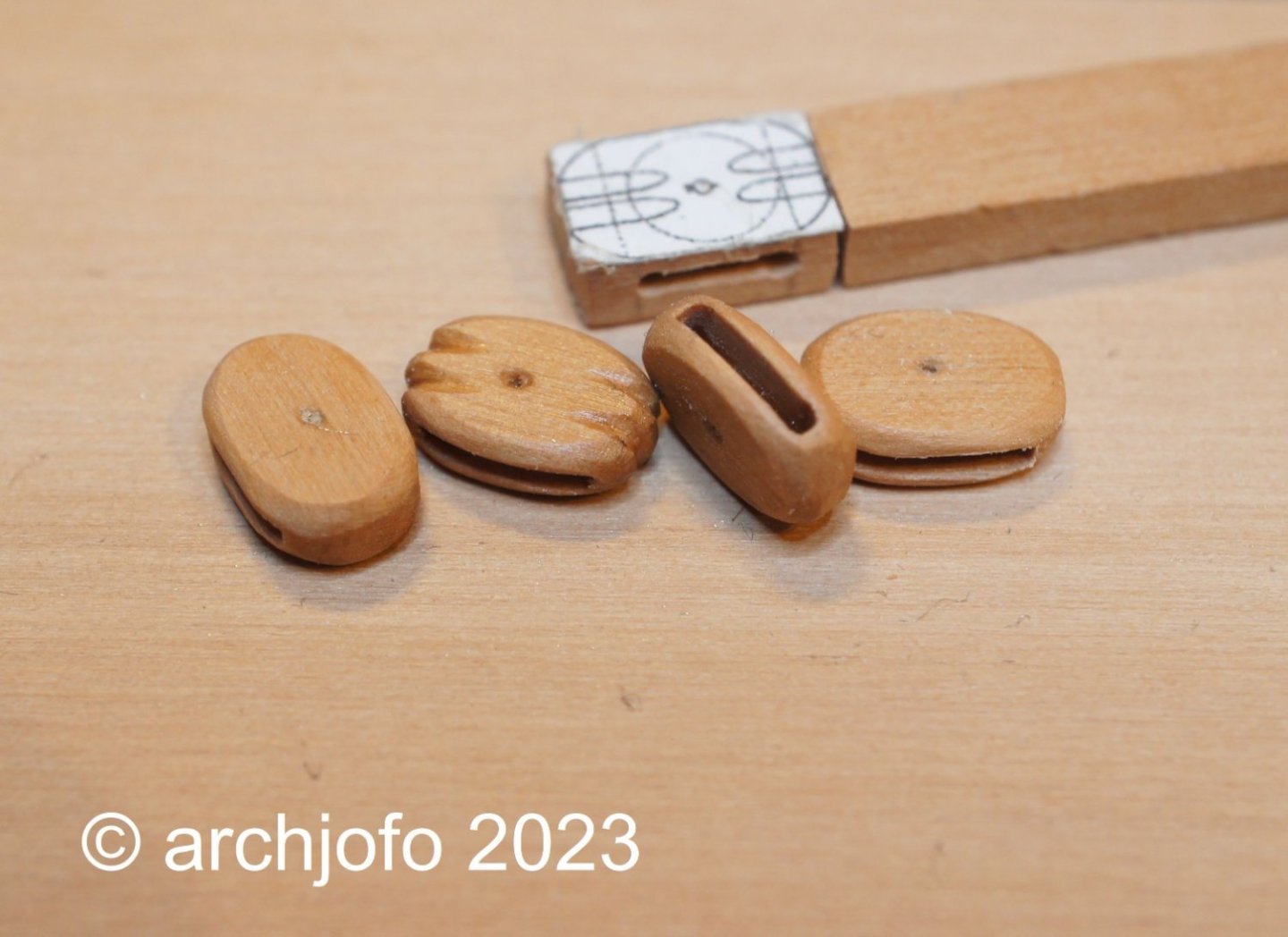
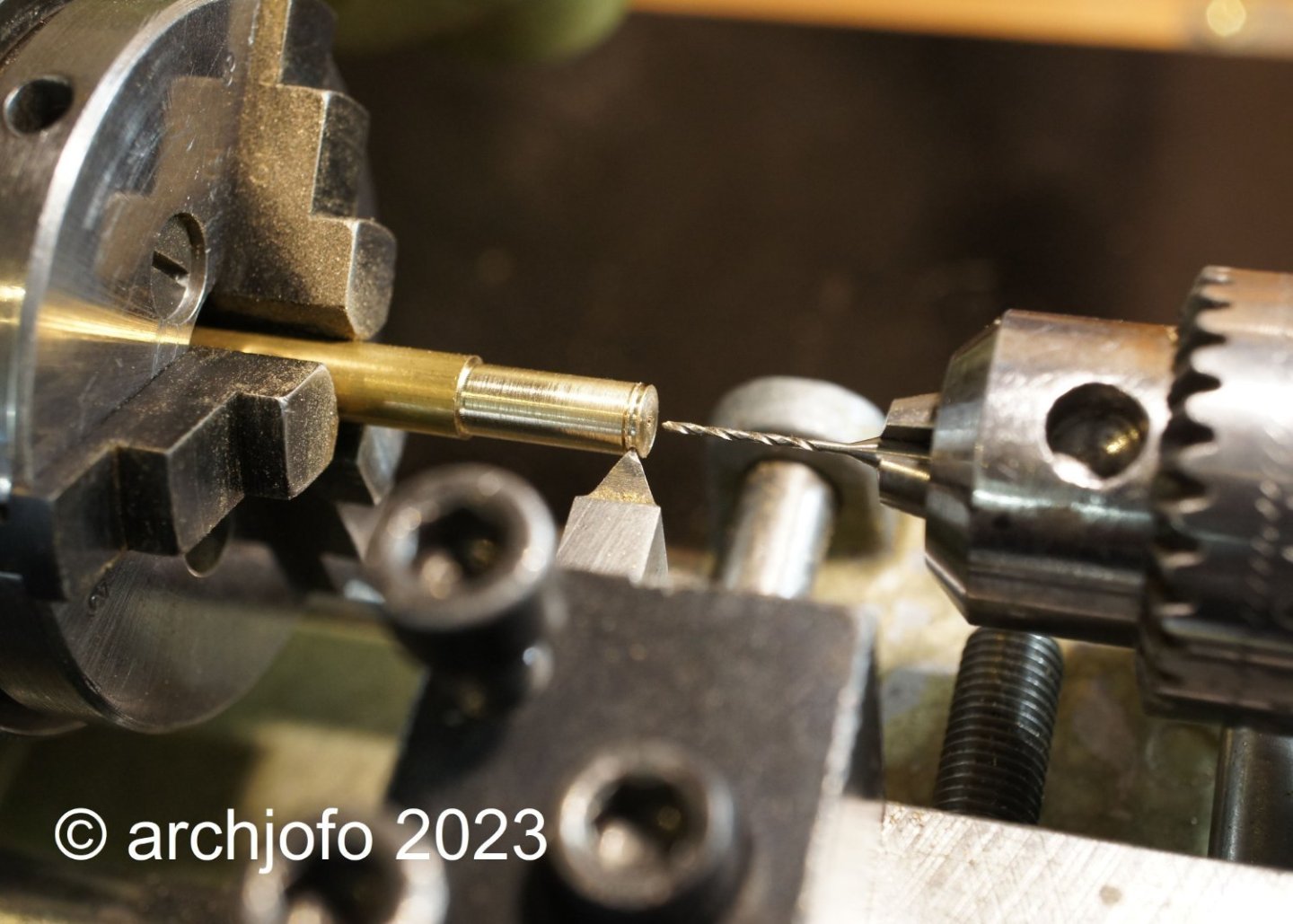
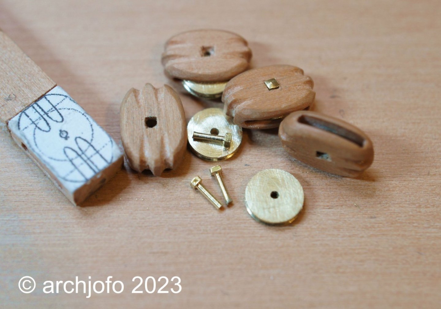
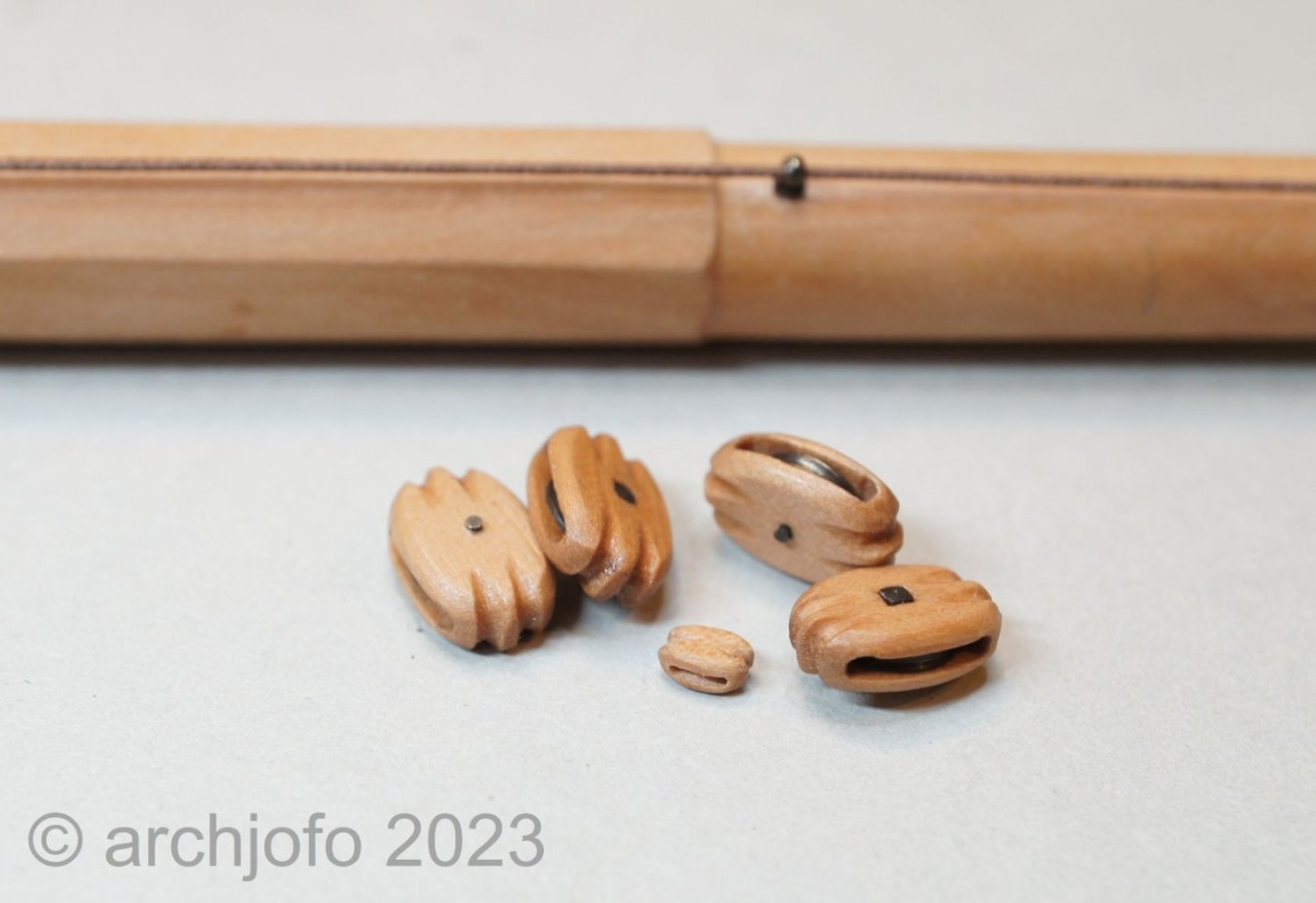
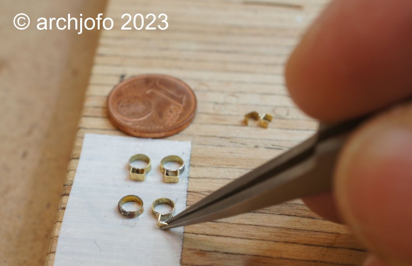
@Jimnclare Thank you for your kind words. Also thanks to all the others for the LIKES. @JerryTodd Thank you for your interest. Correct. As seen in the Constitution picture, the jackstay is an iron bar and not served. Continuation: Equipment of the yards - quarter blocks - poulies d'ecoute et de cargue-point Next up is making the blocks for the lower yards. In the first step I placed the quarter blocks, which were arranged in the middle of the yard using a double strop. These single blocks were used to deflect the topsail sheets and were among the largest blocks on the corvette. These blocks are 8.7 mm long for the main yard of the model and 6.8 mm long for the fore yard. The blocks were made in the usual way and real discs were installed for this size. In the euphoria I accidentally made four 8.7 mm long quarter blocks, although of course only two are needed for the main yard. To produce the discs, a brass rod was turned to the required diameter of 5 mm, axle holes were drilled and grooves were cut. I then sawed off the discs with the jeweller's saw. Here you can see the finished block housing with the discs and axles. In the last picture I have shown the finished quarter blocks for the main yard together with a single block. The block sizes for the model range within this range. After making the quarter blocks for the fore yard, I'll send you a picture to see the size comparison. In the meantime, thankfully, I have also received interesting information from G. Delacroix on the rigging of the yards Up soon …
-
Brig Le FAVORI 1806 by KORTES - 1:55
archjofo replied to KORTES's topic in - Build logs for subjects built 1801 - 1850
Exemplary clean work results in beautiful details. -
La Palme by Tobias - 1:36 - POF
archjofo replied to Tobias's topic in - Build logs for subjects built 1501 - 1750
Hello Tobias, by happenstance I found your report here at MSW today. I know your fantastic work. But it's nice that you also present your work here in this very well known forum. -
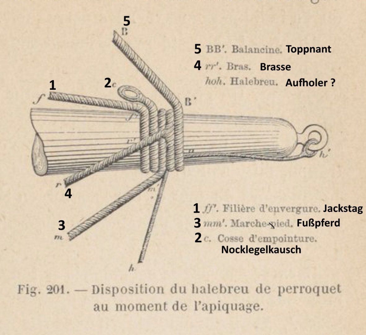
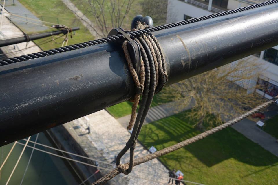
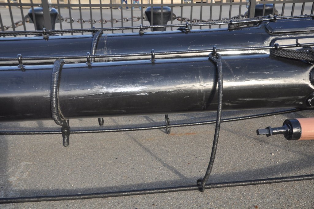
@giampieroricci @B-Ram @albert Hello, Thank you for your interest and good approval, and all the others for the LIKES. Here my further research results to this topic: Continuation: Equipment of the yards - among other things Jackstage - Filière d`envergure. In the meantime, I tried to get more information on this topic via contemporary technical literature. The search in the digital library of the French National Library was successful so far. In the work "Manuel du Manoeuvrier" I found this representation. This is an example of the yard arm of a topgallant yard, where the corresponding ropes are laid out in sequence. Source: Manuel du Manoeuvrier, Agustin Challamel, Paris 1891, page 235 In this respect, I assume that this sequence can also be assumed for the other yards, because Petrejus also describes this arrangement in the book on the "Brigg Irene". It is clear that for the lower yards a hanger or a strop with thimble for the yard tackle must still be considered. I tend to believe, as also described by Petrejus, that later it was also quite common to remove the yard tackle when not in use. For the serving of the jackstay and footropes I show here the following: For this, examples of the USS Constitution and the L'Hermione, showing served variants of footropes, and an unserved jackstay. Source: Internet - USS Constitution Source: Internet - L'Hermione Whereas, to my knowledge, the jackstay on the L'Hermione cannot be historically correct in this way, but it probably serves as a safety line for the crew. This illustration of a jackstay and footrope show unserved ropes. Here you can also see a strop with thimble and hooked yard tackle. Source: Atlas du Génie maritime, annexe No. 1, detail Pl. 19 To be continued ...
-
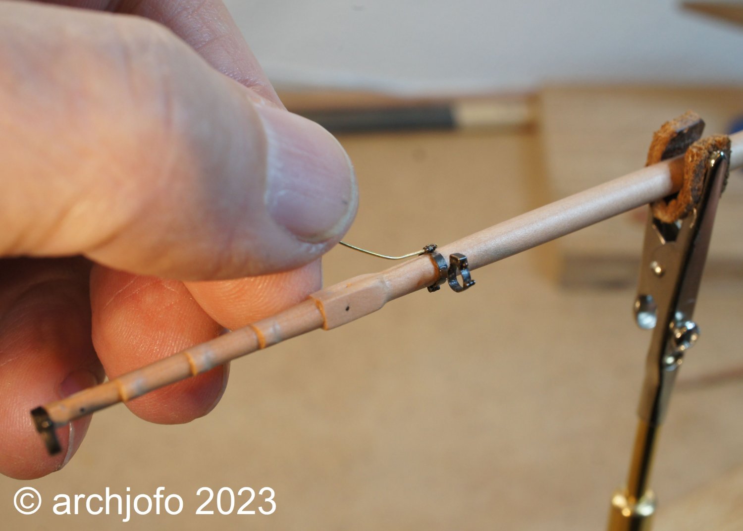
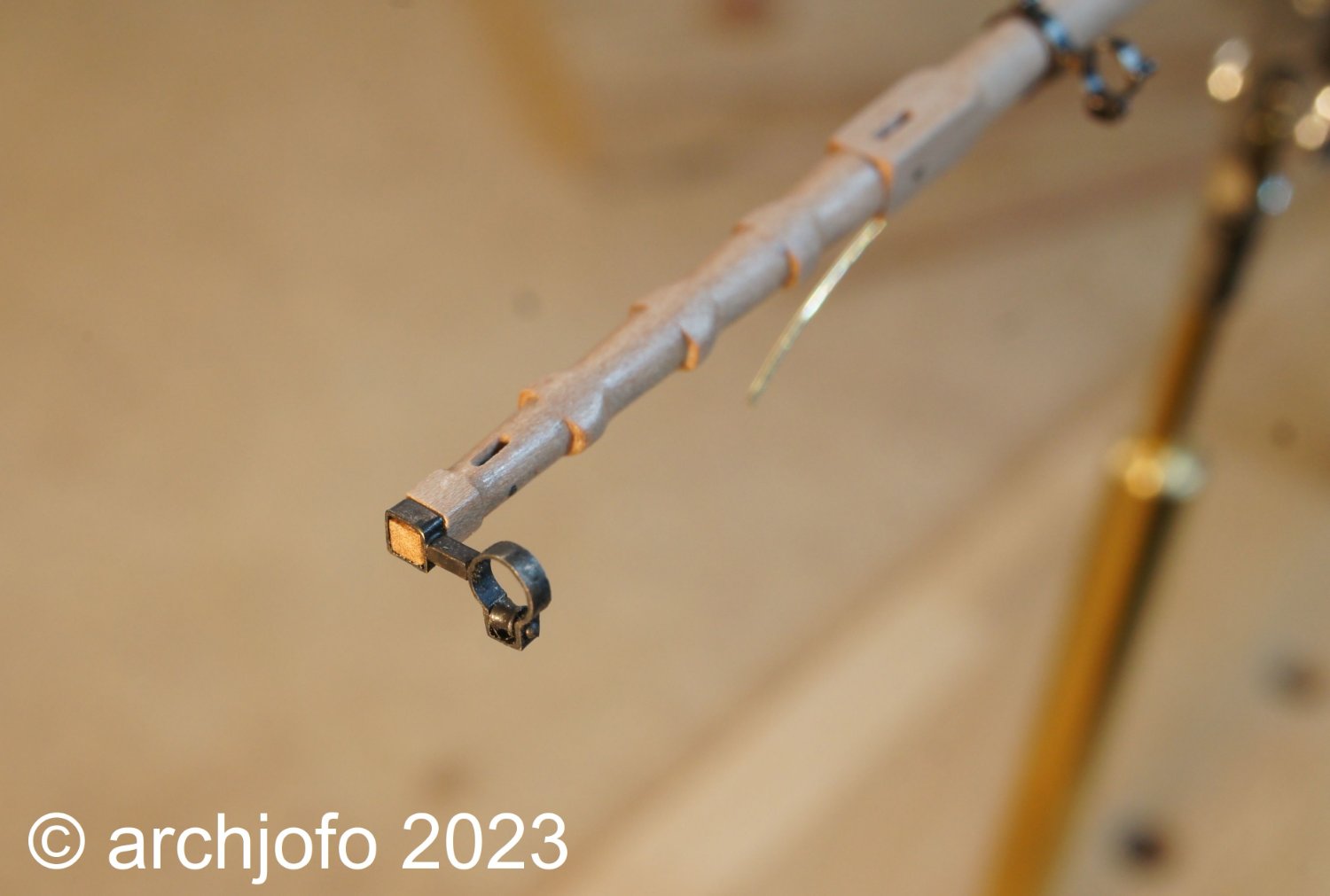
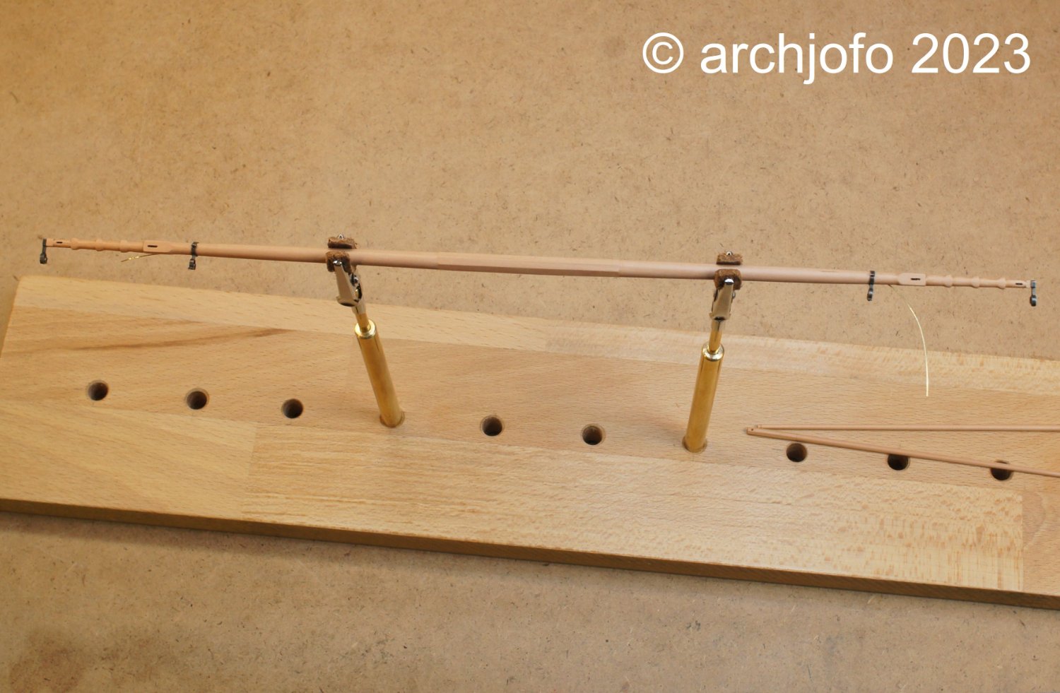
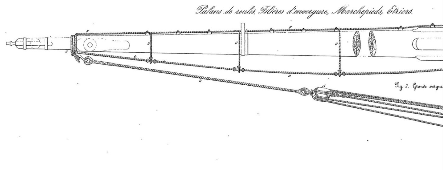
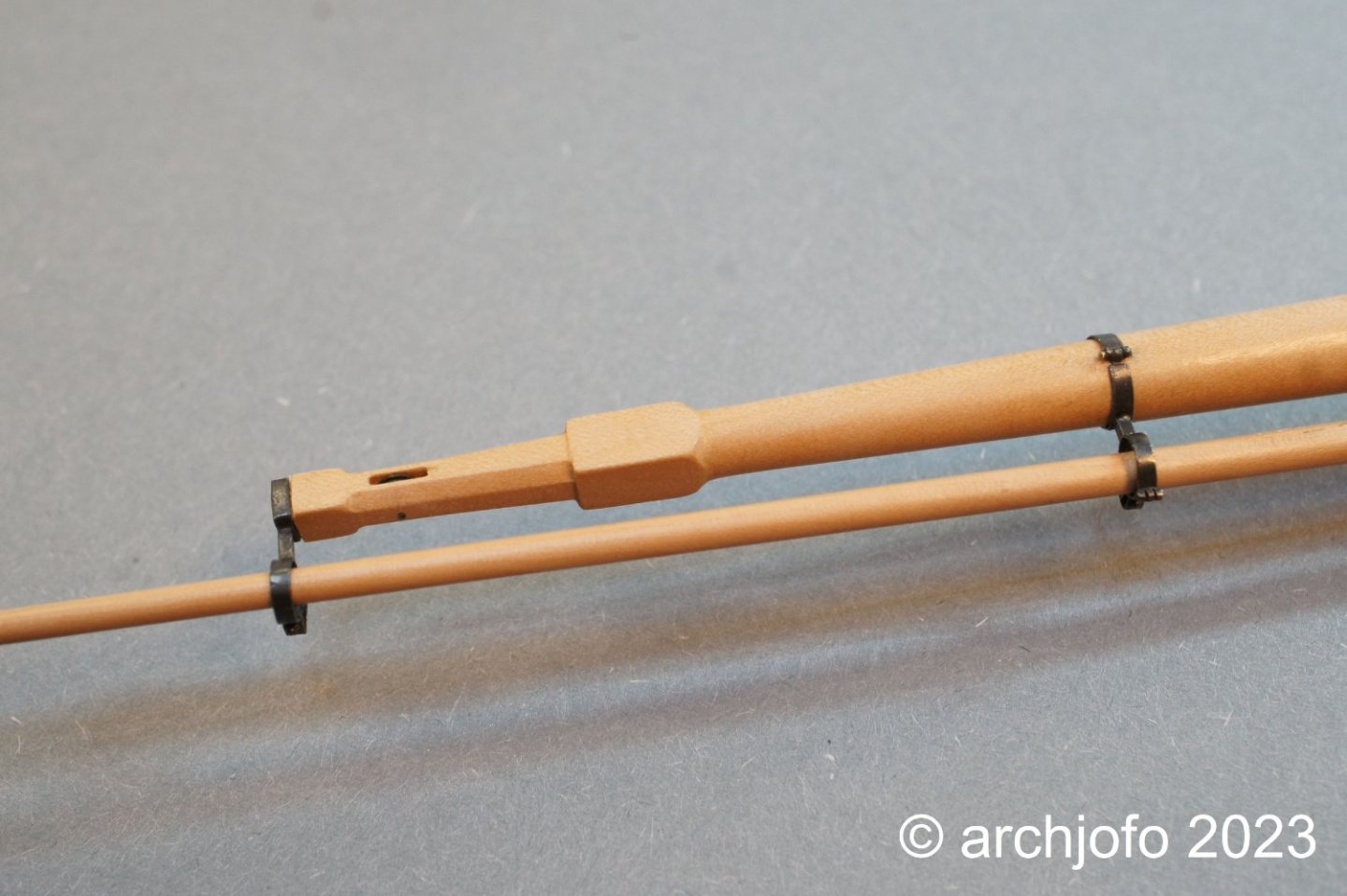
@wefalck Hi, thank you for your interest and the nice note. Also thanks to all the others for the many LIKES. Here it continues with a small update: Continuation: Equipment of the yards - among other things Jackstays - Filière d`envergure. Petrejus writes in his book "The model of the brig of the Irene" on page 207, that around 1811 yards were equipped with jackstays for the first time. By the early 1820s, these were in general use on larger square riggers, Petrejus continues. This is also consistent with statements in the Journal of the German Maritime Archives on the Hamburg Galiot Mary Ann on page 413. Initially these were made of cordage of natural fiber, and later these were made of wire rope or iron rods. As can be clearly seen in some of the pictures of the original Paris model of La Créole, jackstays made of stiffened cordage were also used there. I have not found anything on the plans of Jean Boudriot's monograph on the La Créole itself. Under the illustration on p. 170, however, there is a short description of the jackstays. Accordingly, the sails should only have been attached at the lower and topsail yards by means of jackstays, if I have understood it correctly. The topgallant sails and the royals were obviously attached to the yard in the conventional way by means of a lashing. Source: Monograph La Creole by J. Boudriot, p. 170 Since the jackstays, except for the head cringles, had to take the whole tractive force of the sails, I am of the opinion that massive eyebolts with collars were used to fasten them to the yards. In this respect, I am guided by a drawing from the Atlas du Génie maritime, which shows a massive forged eyebolt. Whether these eyebolts were also used for this purpose, I could not determine. However, this possibility does not seem to me to be completely absurd. Source: Extract from Atlas du Génie maritime Therefore, I made scaled test pieces and mounted them on a yard, which was a scrap from the yard production. After pulling in a served rope of the appropriate thickness, I think it looks quite passable, as can be seen in the following picture. The jackstays were set on top of the yards in the forward area. A served rope was first placed around the yardarm with an eye splice and then passed through the eyebolts, which were attached to the yard at intervals of about 3 m, towards the center of the yard. There at the rope end of the jackstay a thimble was tied in. With the thimble of the jackstay end from the other direction and a lashing tied in, the jackstays were braced in the center of the yard. I will soon start making and installing the jackstays. At the same time, there are still a number of questions to be clarified regarding the equipment of the yards, such as: - Sequence of ropes to be attached to the yardarms (jackstays, lifts, braces, footropes, yard tackle etc.) - design and fastening of the stirrups - number and size of yard blocks - yard hangers and fastening etc. The extent to which the French, like the English, had yard tackles permanently attached to the main yard and fore yard, or only when needed, also needs to be clarified. On the Paris model, however, there are no yard tackles to be seen. However, I miss corresponding hangers on the yardarms to attach them when needed. As described by Petrejus, it would be conceivable to have strops around the yardarms to which the pendants including tackle could be hooked if necessary. Would be very grateful for hints and suggestions on the open questions.

-
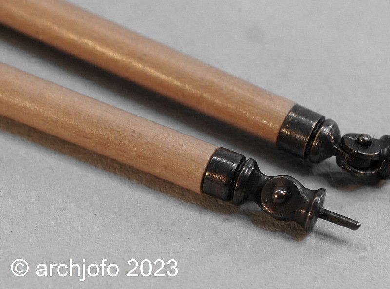
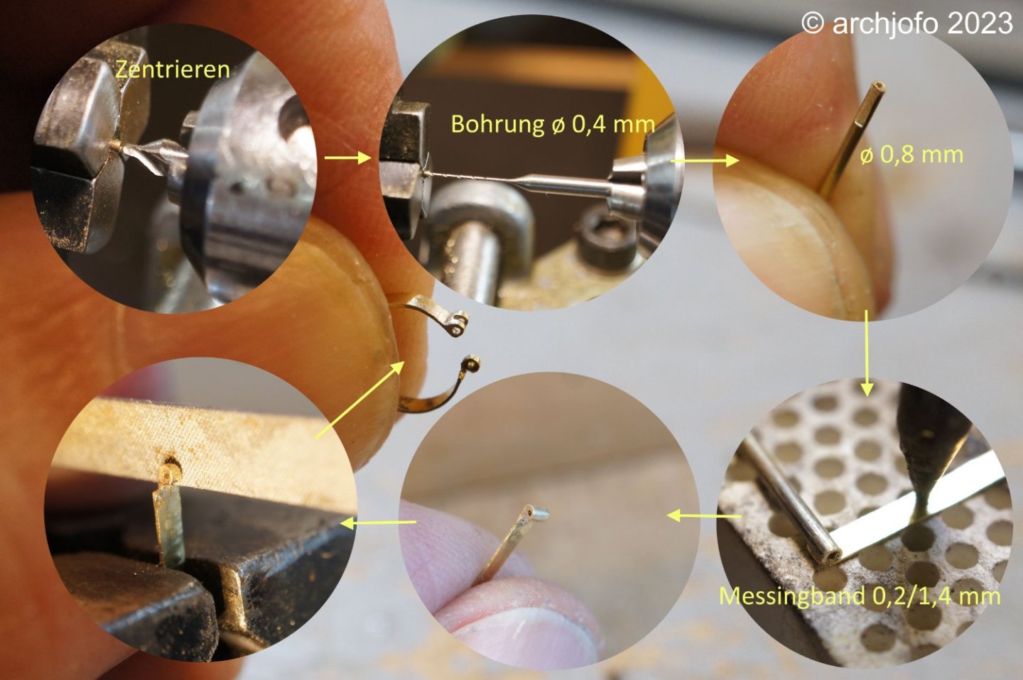
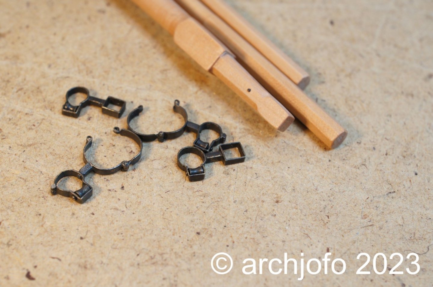
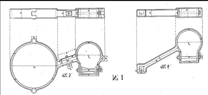
Fore studding sail booms / fore stays - Arc boutant de misaine The lower studding sail booms were attached to the fore channels of the La Créole with a hinged fitting. Source: Monograph on the La Créole by J. Boudriot I made these lower studding sail booms together with the yards from pear wood (largest diameter 3 mm) some time ago. Likewise, the corresponding fittings with the eyelets for hooking in these booms were made and mounted on the front fore channels some time ago. Now these fittings had to be manufactured. For the execution of these fittings I oriented myself at a corresponding illustration of the Paris model in the monograph. This design corresponds with drawings in the Atlas du Génie Maritime. Source: Monograph on the La Créole by J. Boudriot On the following picture collage, I have only shown the essential steps for the production of the fittings. I think the pictures are self-explanatory. The slots were milled. Unfortunately I did not take any pictures of this. The next picture shows the blackened and mounted fittings. And finally a picture of how the lower studding sail booms are hooked to the fore channels. These booms are secured to the front shrouds in the upper area by a lashing when not in use. The next step will be the jackstays for the lower and topsail yards. There are still some details to be clarified. So far I could not find much information in the relevant literature or on the internet. Would be very grateful if one or the other could contribute something to this topic. Continuation follows ...
-
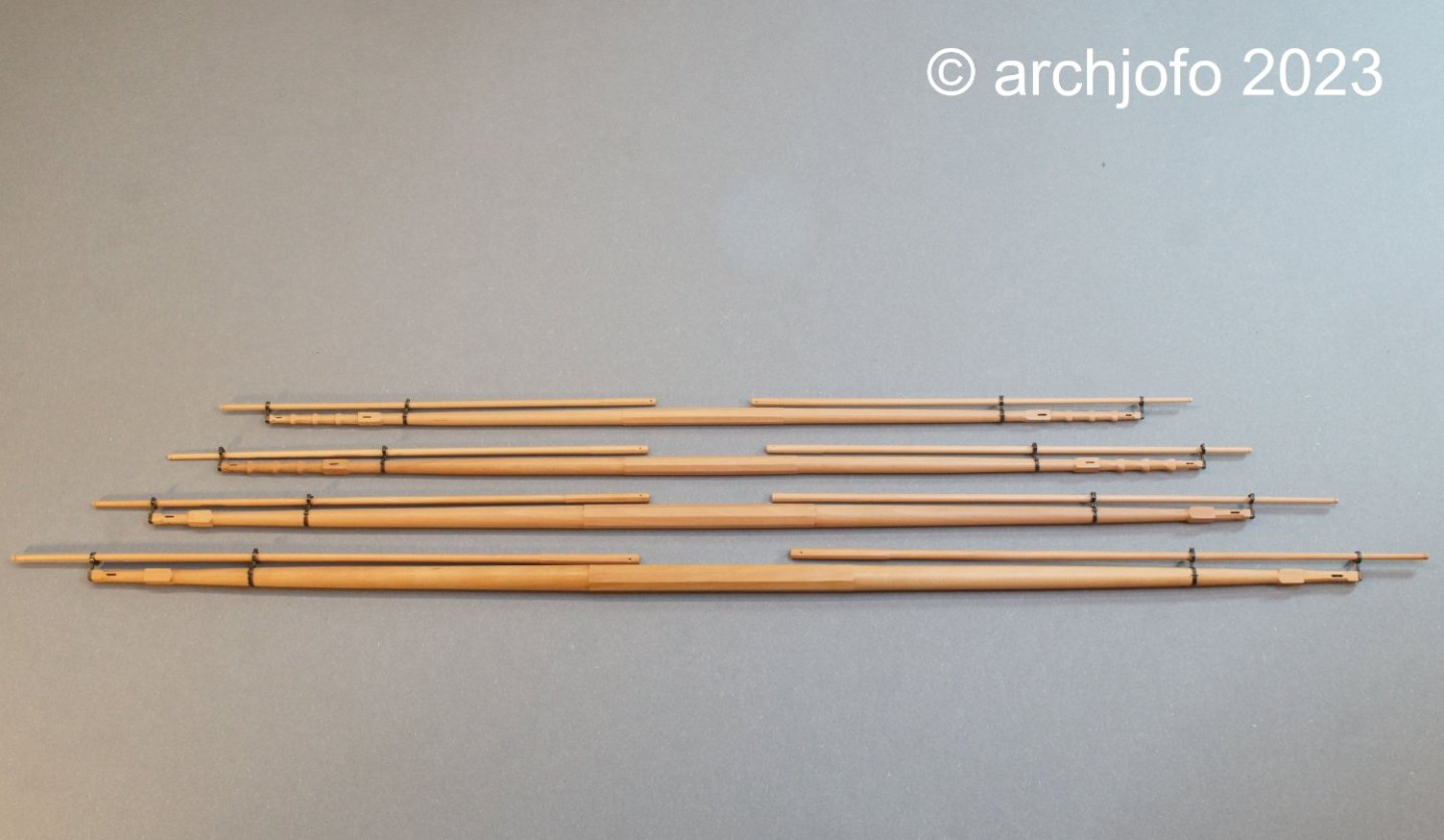
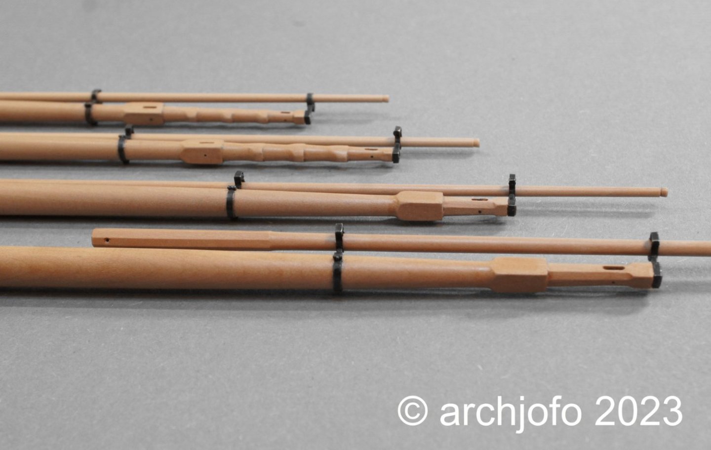
@Wintergreen @wefalck Thank you very much for your interest and appreciation. Completion: Main yard - Studding sail boom iron - Cercle de bout-dehors de vergue With the production of the studding sail boom irons for the main yard, this chapter can be brought to a close. The first picture shows the already mounted studding sail boom irons of the main yard. In the next pictures I have gathered all the yards that have been equipped with studding sail boom irons. For the further equipment of the yards with blocks, footropes and jackstays, various details still have to be clarified. More about that soon ...
-
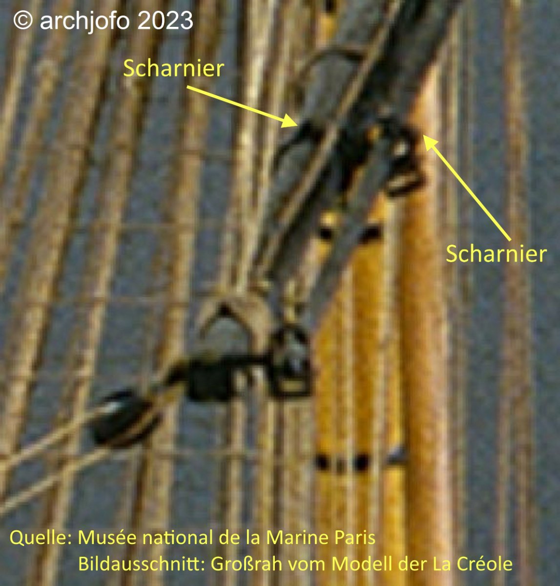
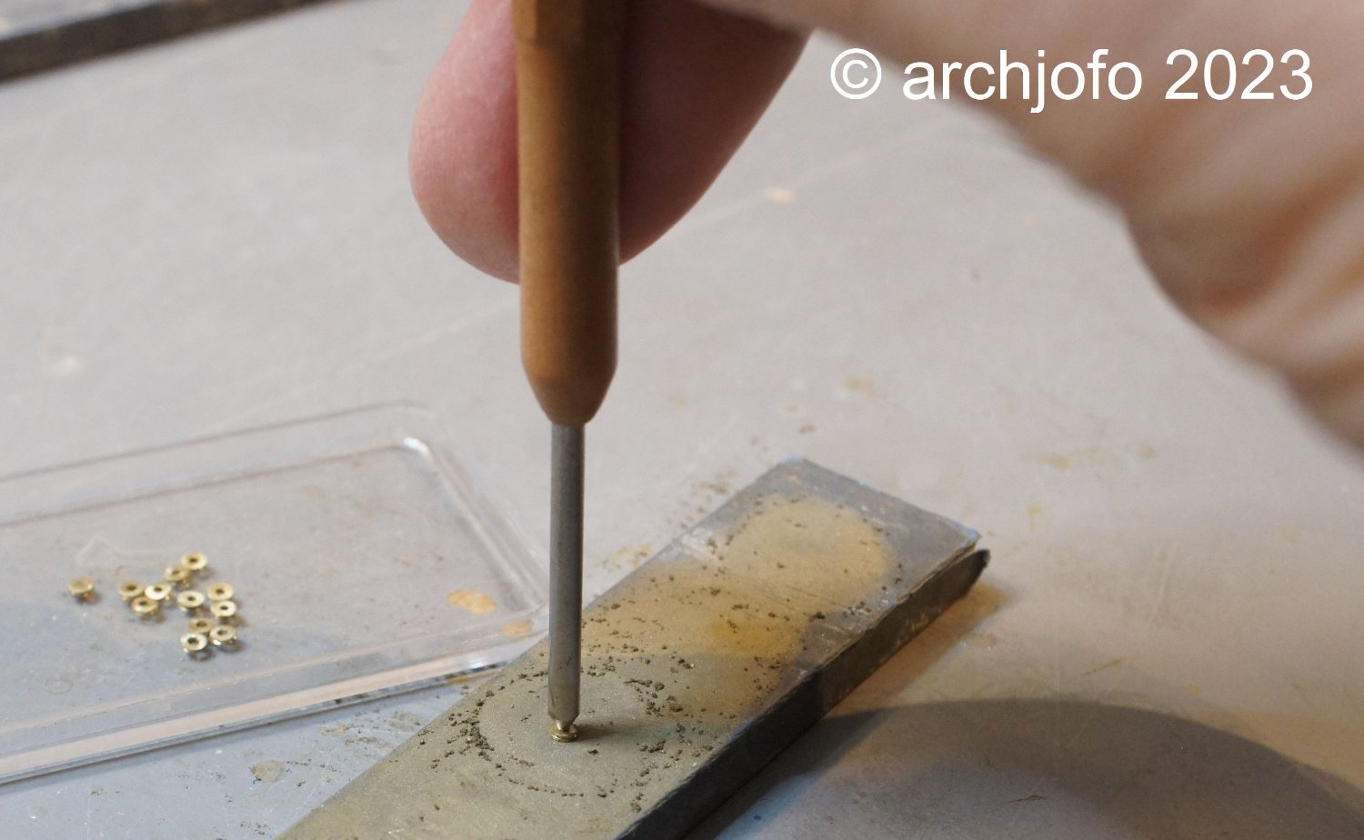
Continued: Fore yard- Studding sail boom irons - Cercle de bout-dehors de vergue In the meantime, I also made the studding sail boom irons for the fore yard. In this context, I would like to go into a little more detail about the method of making the hinges for the two-piece mast clamps. In the studding sail boom irons for the fore yard, the hinge lugs were still bent. In the meantime, I have refined the method, as can be seen in the following photo collage. I think the pictures speak for themselves: To finish this part, here's a picture with the studding sail boom irons for the fore yard already blackened. Finally, only the studding sail boom irons for the main yard remain to be made. More about that soon ...
-
Brig Le FAVORI 1806 by KORTES - 1:55
archjofo replied to KORTES's topic in - Build logs for subjects built 1801 - 1850
Fantastic job ! -
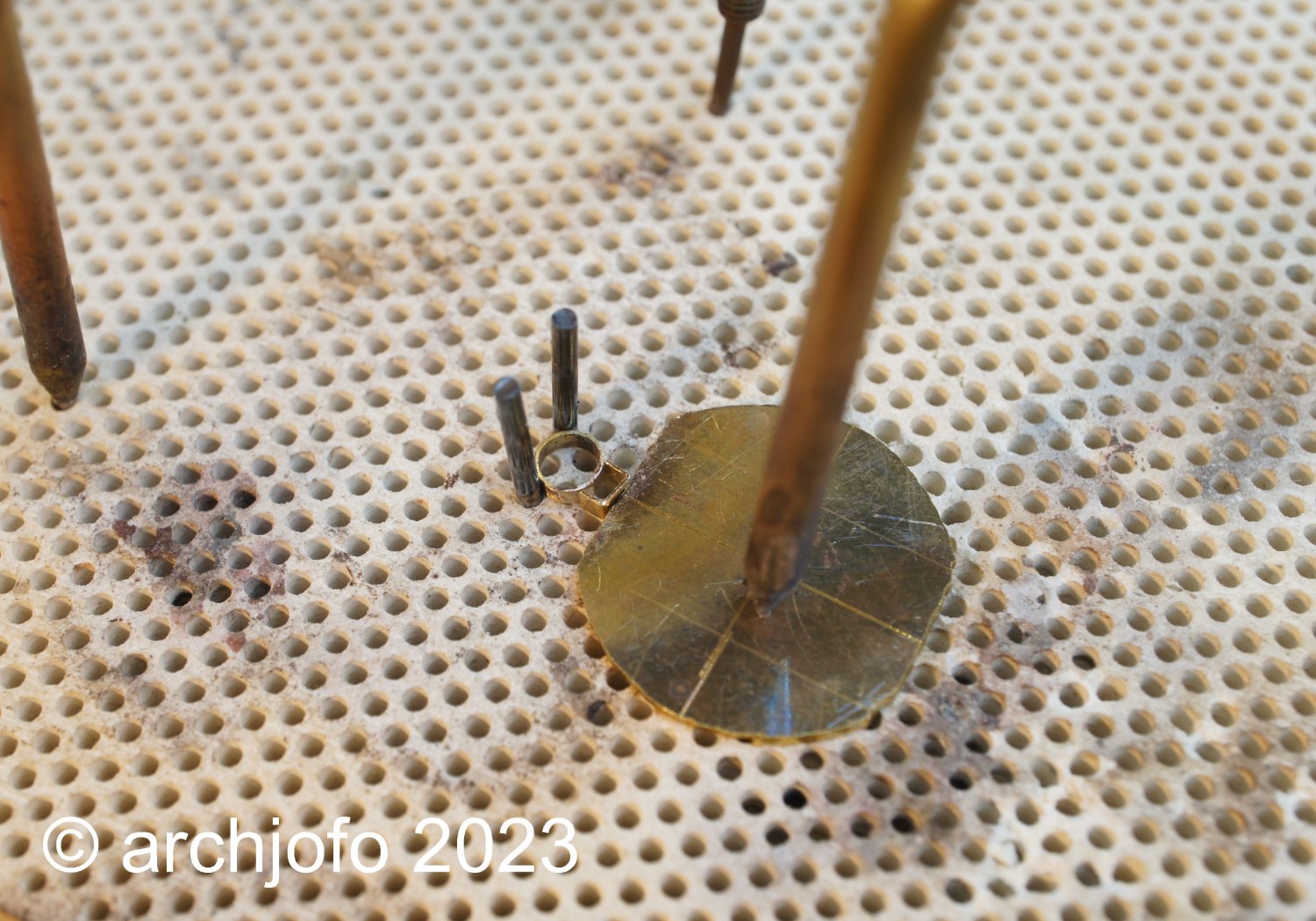
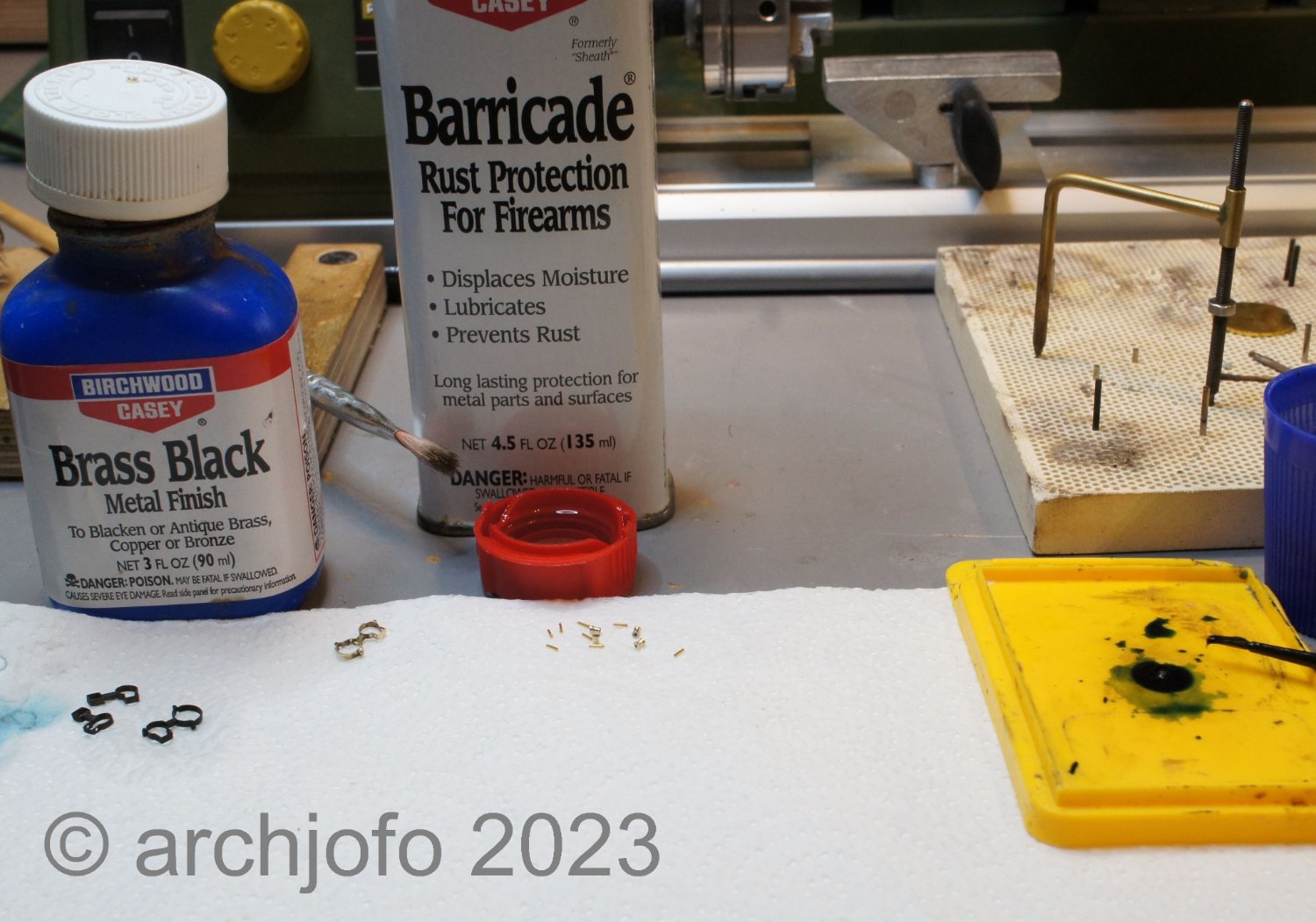
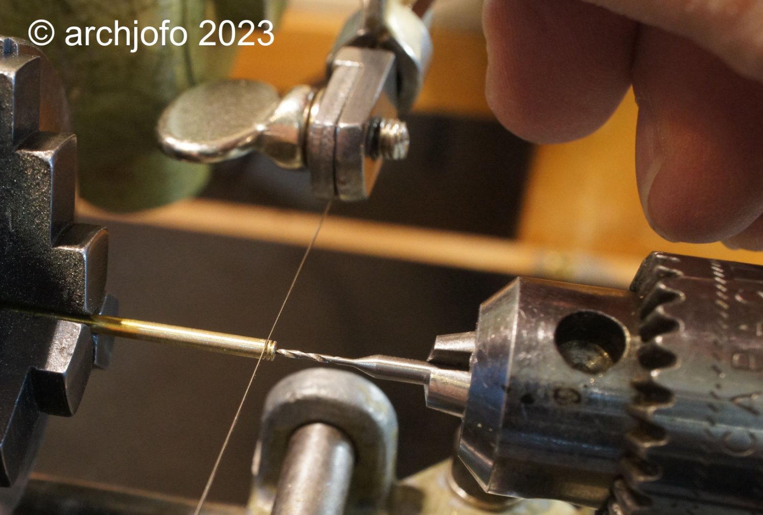
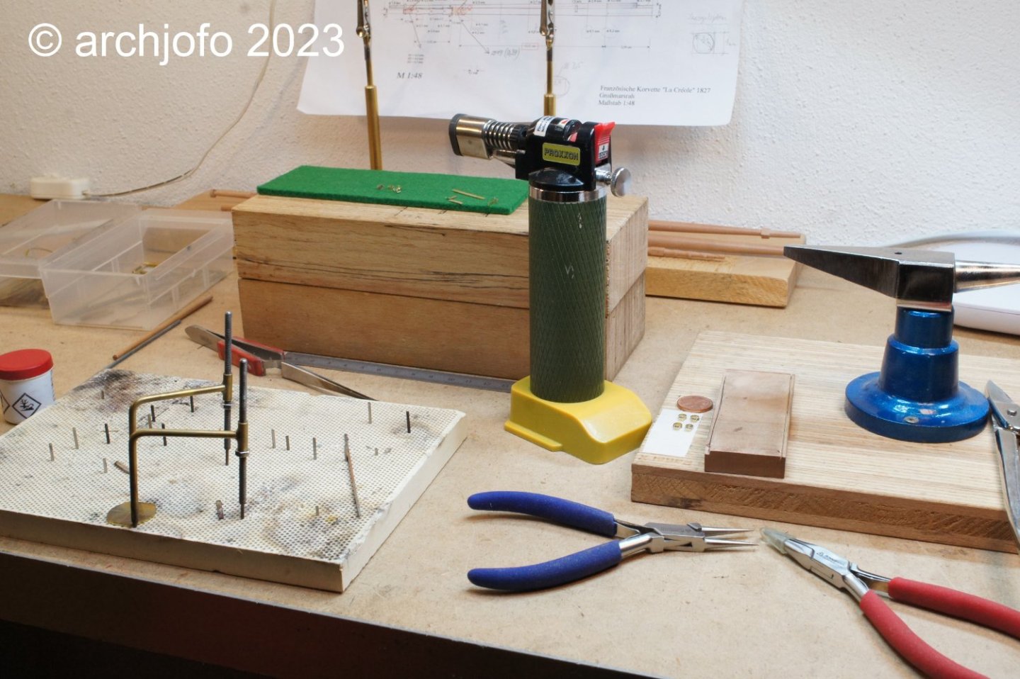
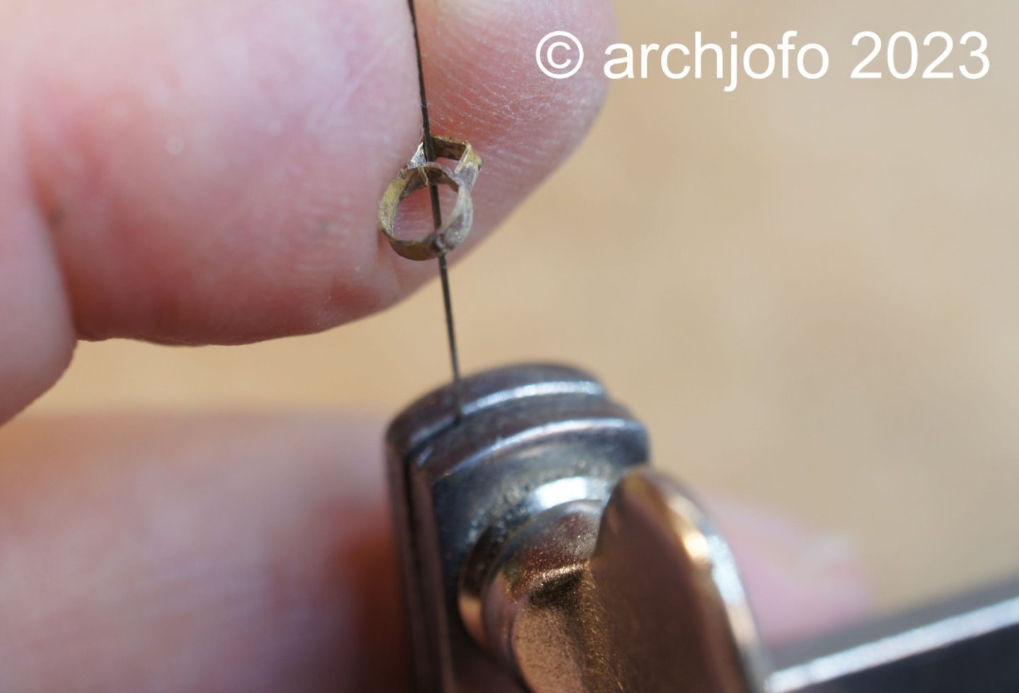
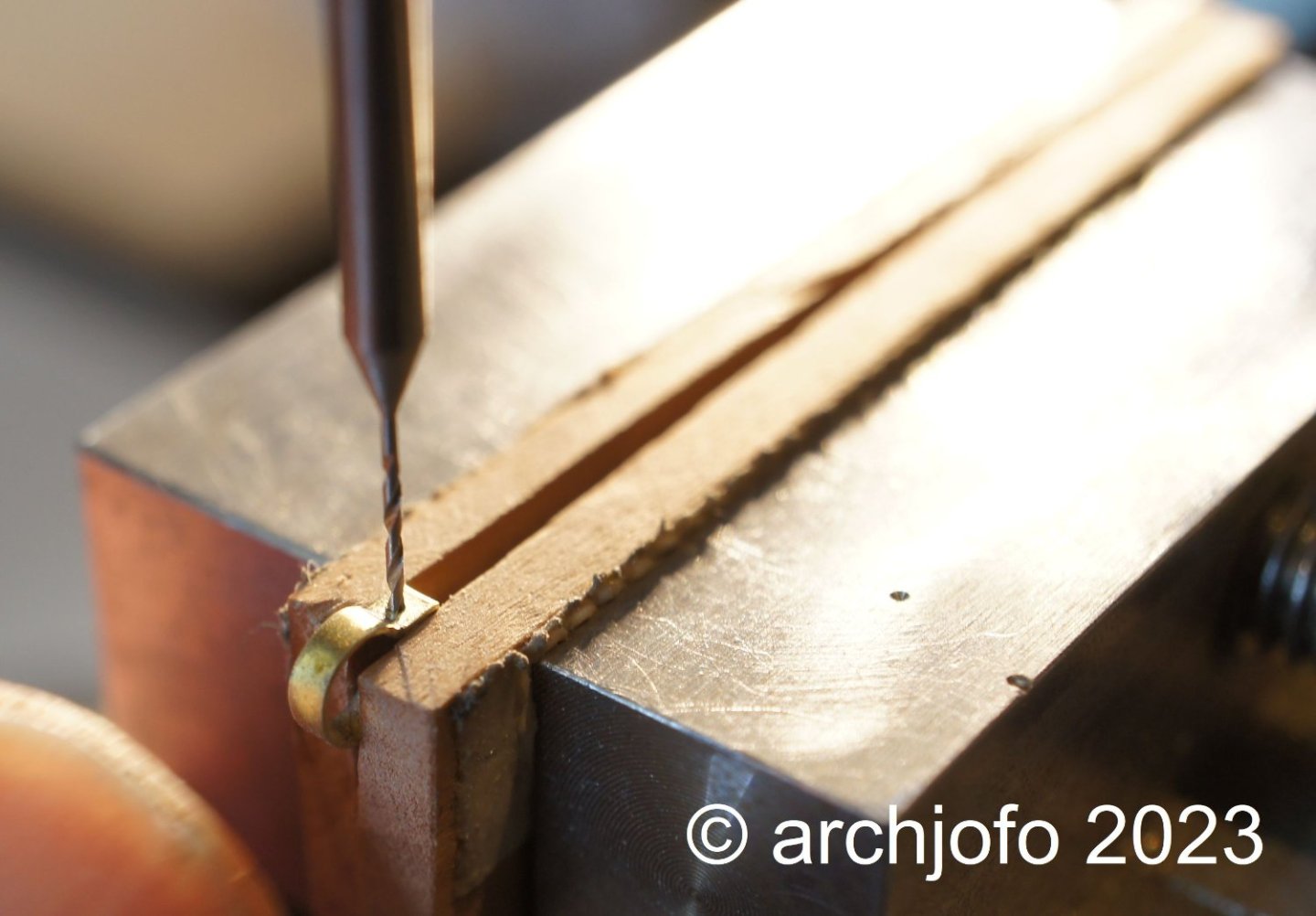
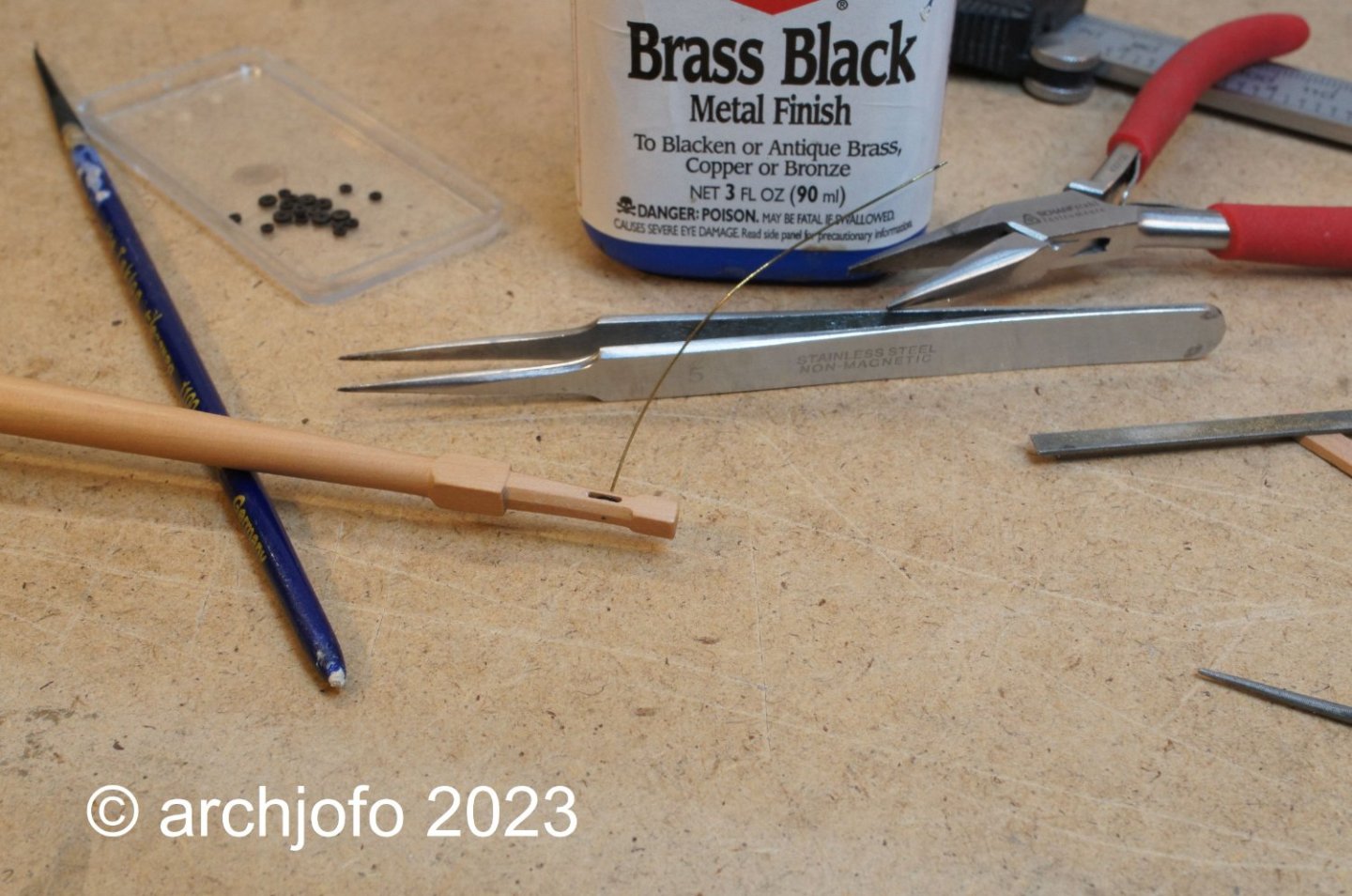
Continuation: Main topsail yard - studding sail boom iron - Cercle de bout-dehors de vergue I continued with the studding sail boom irons for the main topsail yard. Since I had thoughtlessly started to make the rings, I forgot to make the bulge for the rollers. Since these rings were already soldered, I tried to solder on this bulge, which then also worked quite well and the even result became more precise. As they say: the proof of the pudding is in the eating ...😁 The following picture shows the rings with the parts to be soldered on. Here on this picture you can see my " soldering station ". On the ceramic hole plate you can fix the parts to be soldered quite well. The jeweler's saw is then used to remove the segments of the rings that are not necessary. The next picture shows the drilling of the roller bearings with a 0.5 mm drill. In the picture, all studding sail boom iron for the main topsail yard are united before blacking. The inside diameters of the spar hangers for the fore topsail yard are 2.7 mm, while those for the main topsail yard are 3.2 mm. For blackening, I still use Brass Black, as I have had very good experiences with this agent. I coat the parts with a brush until they get the desired coloration. This proven method of working allows me to use the agent very sparingly. The last two pictures show the studding sail boom irons already mounted to the main topsail yard. Next, I make the irons for the fore yard. At the same time, I'm researching other equipment for the yards, such as attachment of the footropes, jackstays - yes or no, and so on. See you soon ...


-
@jdbondy Hello, very interesting and beautiful models. Thanks for the pictures.
-
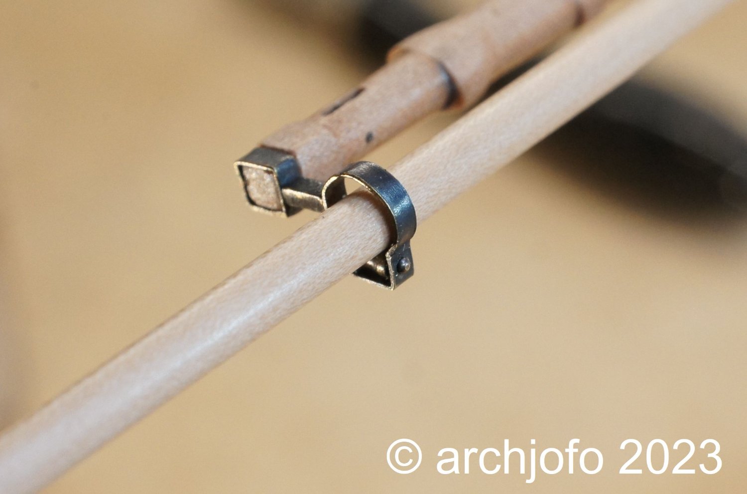
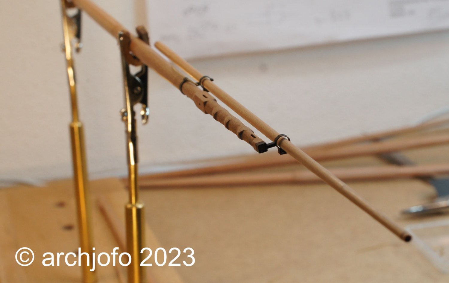
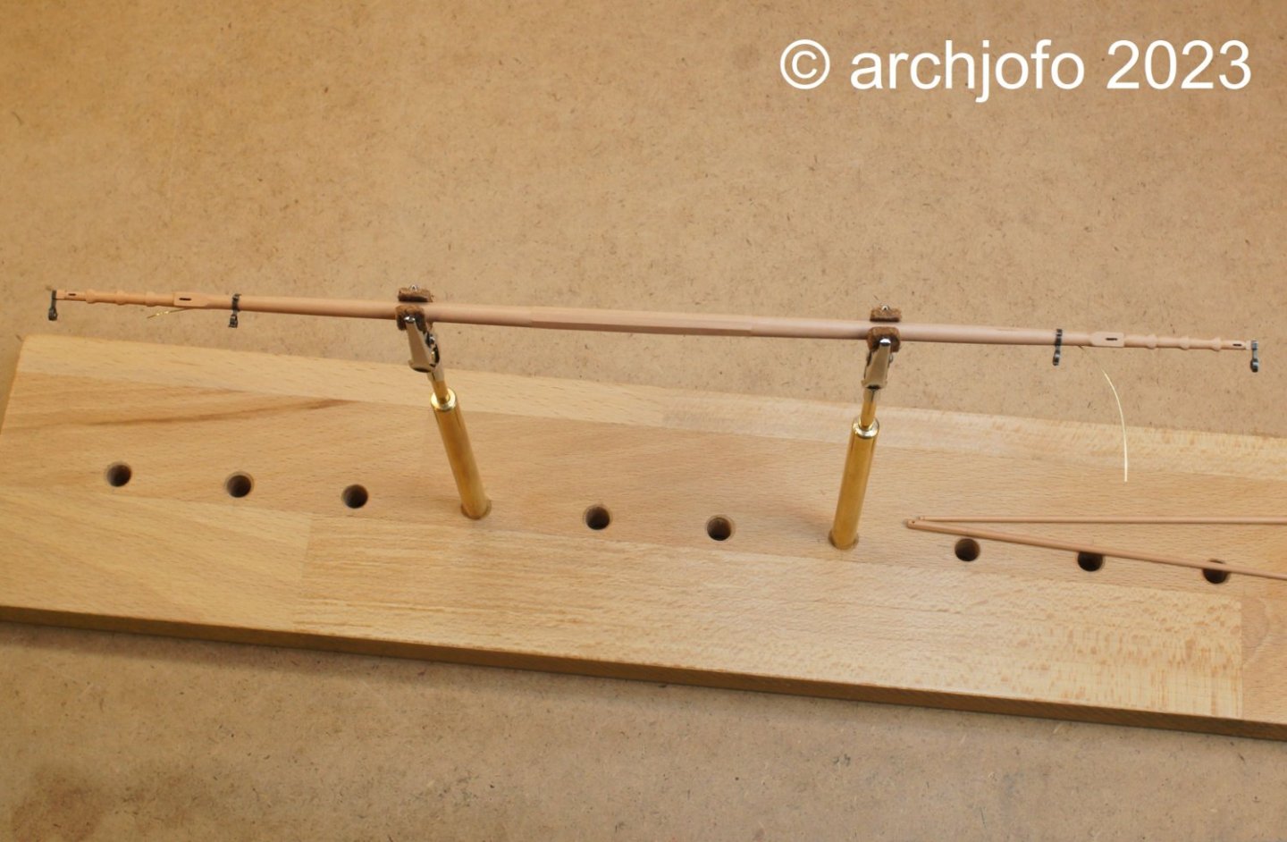
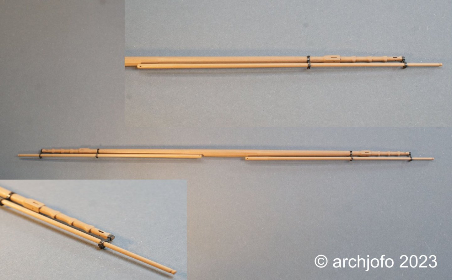
@wefalck Hello Eberhard, thanks for the nice comment. Continuation: For topsail yard - studding sail boom iron In the meantime I also made the outer studding sail boom irons for the fore topsail yard. Like the inner irons, they were made of brass strips with a width of 1.3 mm and a thickness of 0.25 mm. For brazing with a silver brazing paste I fix the pre-prepared parts on a ceramic plate, as already shown several times. With the following picture I show how the assembly of the inner studding sail boom irons is done. The brass wire ø 0.4 mm, which still has to be shortened, takes over the function of a safety pin. The next picture shows the outer iron of the fore topsail yard. The end of the yardarm is square with dimensions 2.2 / 2.2 mm. In order to be able to carry out the assembly and rigging work on the yards comfortably, I made myself this holding device. And finally, an overview of the construction status of the fore topsail yard, with the studding sail booms, which in the meantime has each received a hole at the octagonal end. At the outer end, a notch has been added for fastening the blocks. The next step is the studding sail boom irons for the main topsail yard, the dimensions of which are somewhat larger. To be continued ...


-
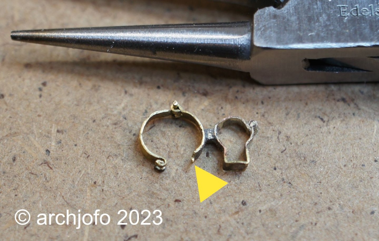
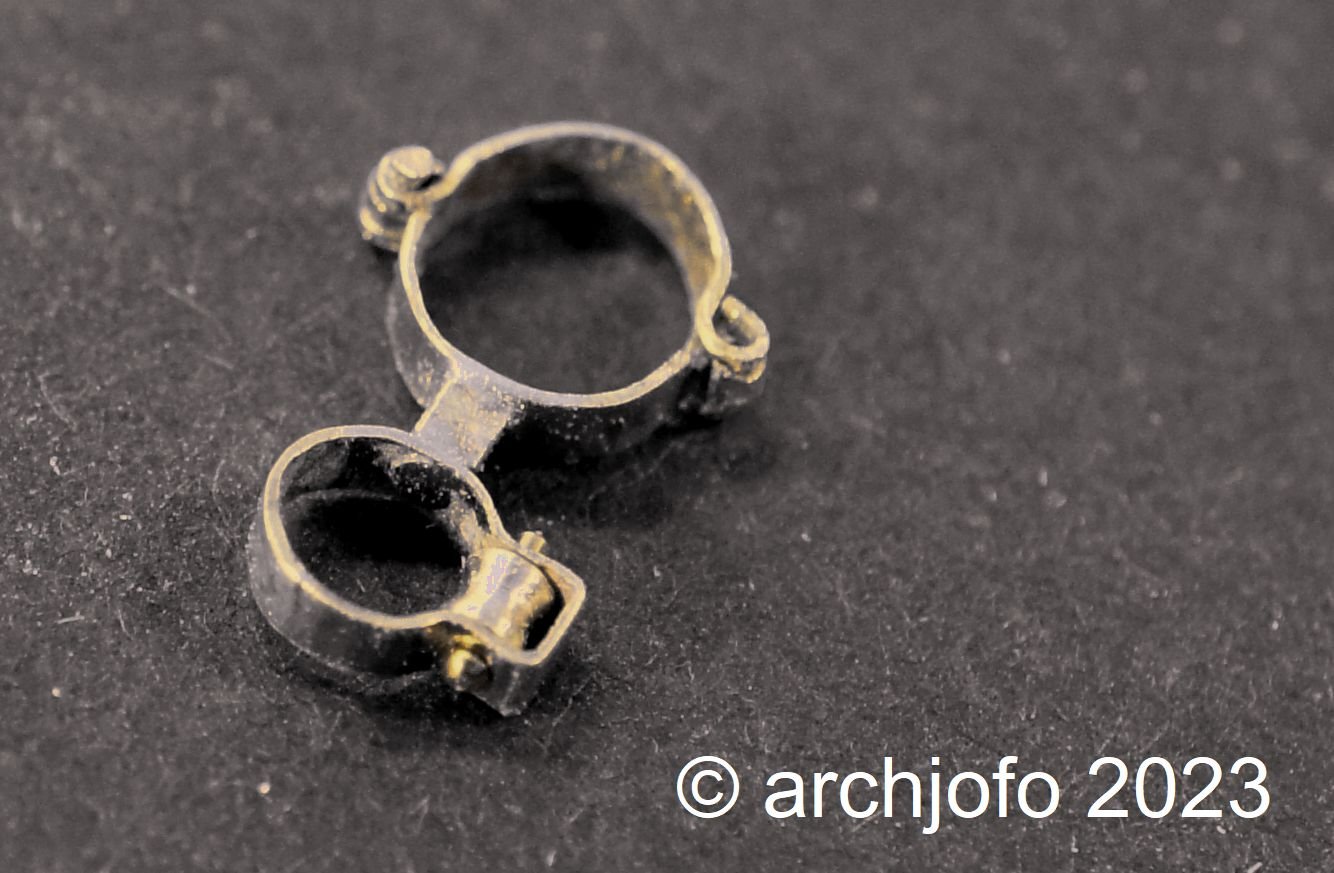
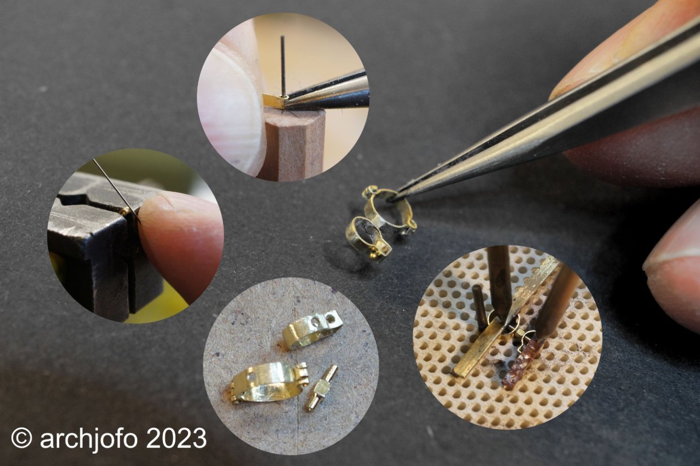
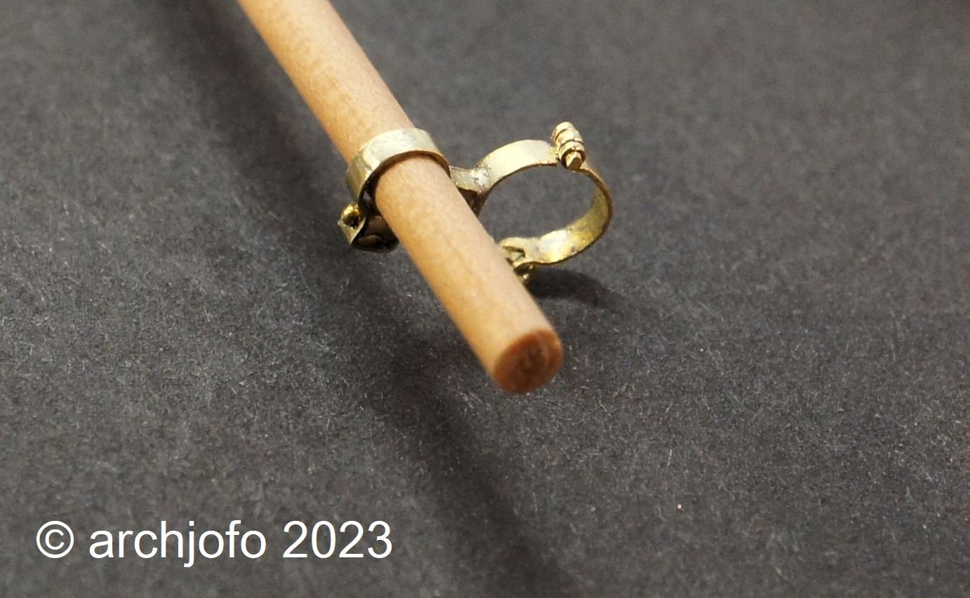
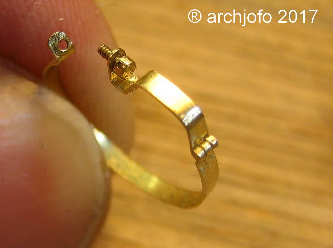
@druxey Thanks for your nice comment. Thanks also to all for the many LIKES. Continuation: Equipping the yards - studding sail boom irons After initial problems and a failed attempt, I set out with new courage to make another one. Probably to avoid the mistakes of the first attempt, such as brazing the fine parts of the hinges too much heat, so that they then ultimately become brittle and break off (see picture). In principle, it would also have been possible to make these joints with soft solder. However, for reasons of strength, I chose brazing. On the next picture I show a photo collage, where single steps for making the studding sail boom iron are shown. On the next picture you can see the studding sail boom iron still in uncleaned condition after brazing. The outer ring is still missing the hint of a hinge, which I will fix with soft solder. Here a picture with spar: And finally the result for the two inner studding sail boom irons of the fore topsail yard. Making the outer studding sail boom irons should be much easier. To be continued ...

-
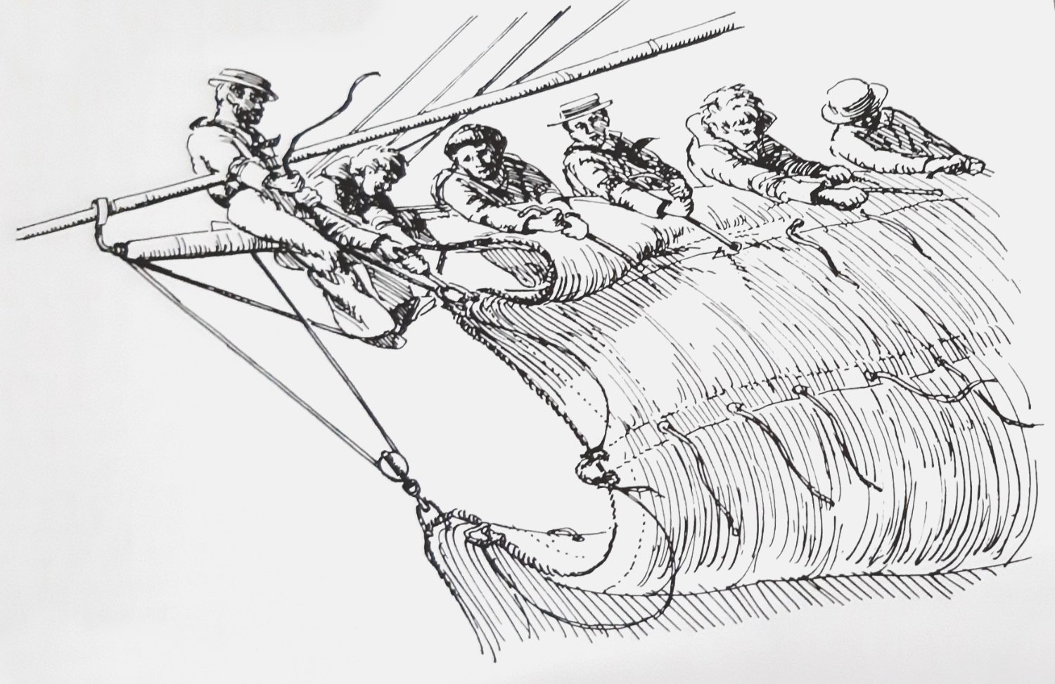
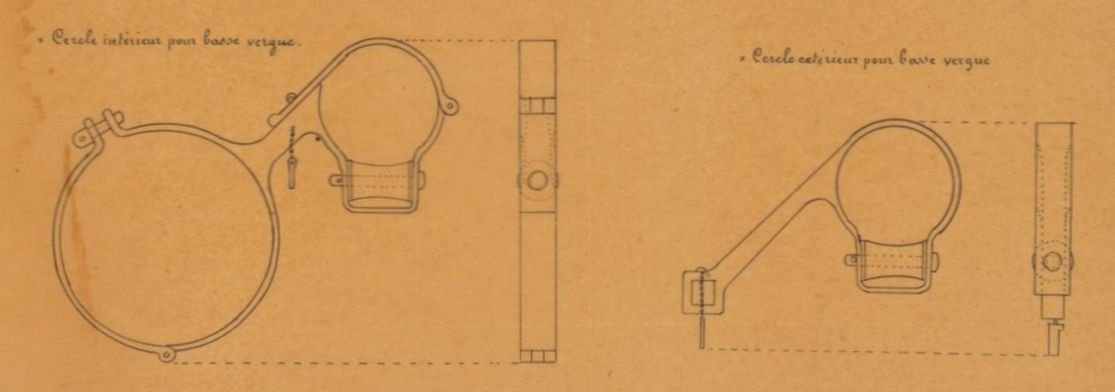
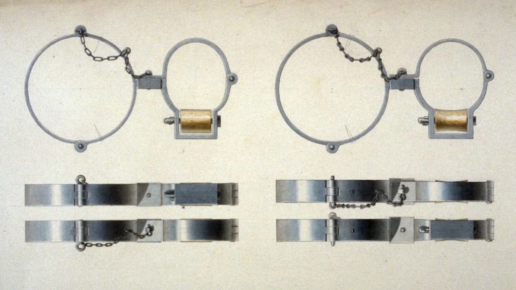
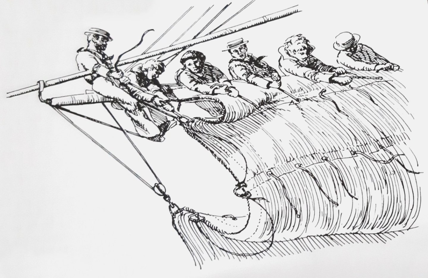
Continuation: Equipping the yards - studding sail boom irons Since I am also interested in how studding sail booms work, that is, how to deploy and attach them, I tried to find more information in the relevant literature and on the Internet. In particular, the book "Seamanship in the Age of Sail" by John Harland describes, among other things, the handling of studding sail booms. This naturally results in various details on the spars themselves (of which later) and in this case on the studding sail boom irons. Source: Seamanship in the Age of Sail, John Harland, p. 147 The preceding picture from this book explains very impressively that the studding sail booms, which were a handicap when sailing, were taken up and attached to the shrouds. To make this possible, the inside boom irons were hinged to open, which can also be seen in the contemporary drawings below. As can also be seen, these examples have different angles, depending on their chronological placement. This also corresponds with the observations of the photographs of contemporary ship models of the Musée national de la Marine. Source: Internet_MSW_Archives_G. Delacroix_ca.1830 Source: Atlas_Brest_1850 Source: Atlas_Toulon_1854 As mentioned before, the Paris Museum has kindly provided me with a high-resolution overall image of La Créole, from which I can obtain additional information to Jean Boudriot's monograph. Especially in the case of the studding sail booms, it can be seen that they were clearly arranged in front of the yard, without angles as shown in the monograph. This also corresponds to the temporal context. In this respect I orientate myself for my model on the drawing, which I received thankfully from G. Delacroix via MSW. Similarities between this drawing and the original Paris model, as shown below, are clearly recognizable. Also I see there the already described details on the historical drawings confirmed. Now I will get to work on the realization for the model. I hope to find a way to produce these difficult details as far as possible. A special challenge is the mounting of the inside studding sail boom iron, because I have to choose a two-piece design for it due to the expansions at the yard arms, if possible with hinges like on the original. I have already made comparable hinges for this model as attachment for the front fishes. But this time it has to go one size smaller. I decided to make the studding sail boom irons for the fore topsail yard first, because they have the smallest dimensions. Bigger is always possible... More about that soon ...

-
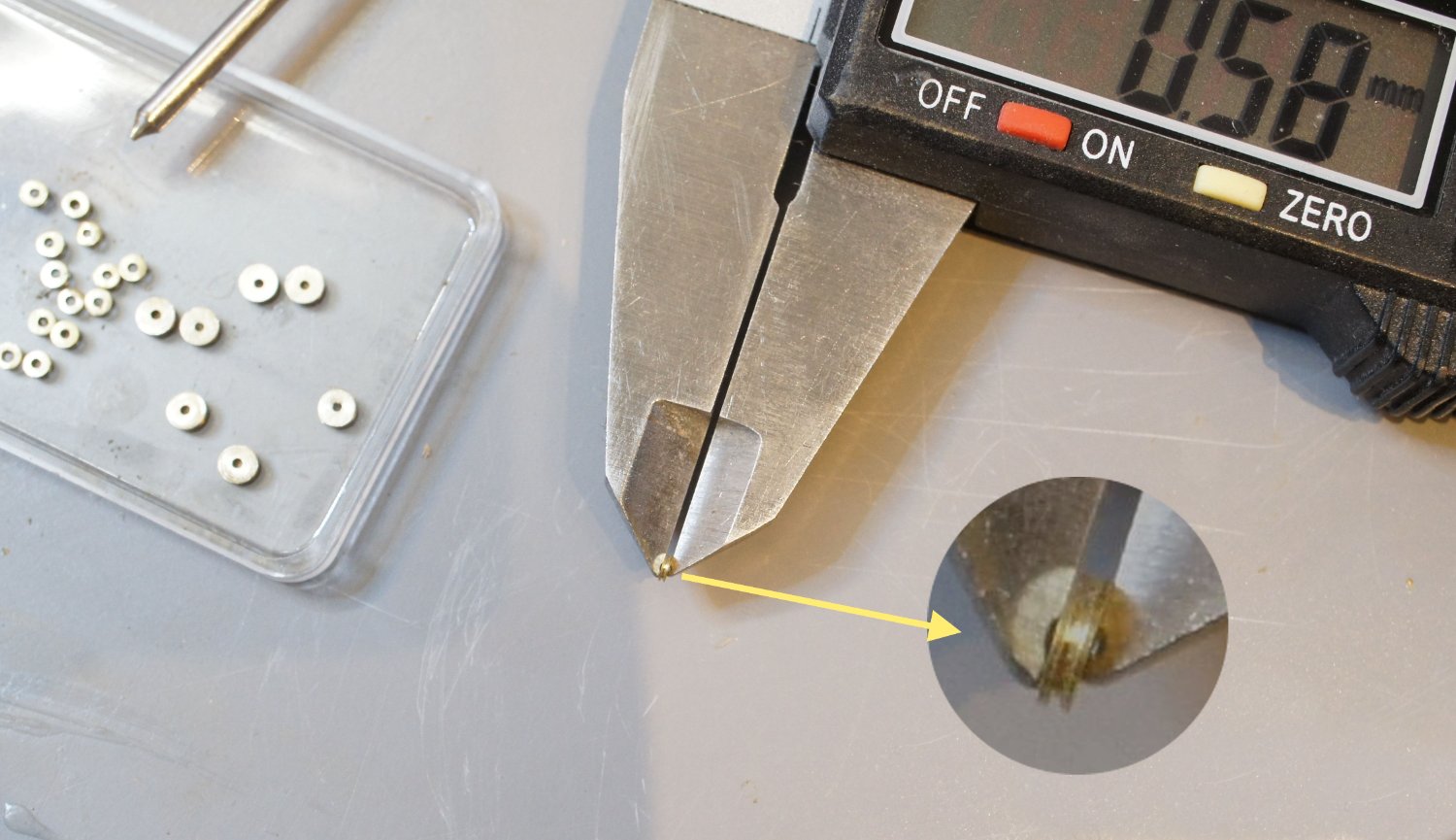
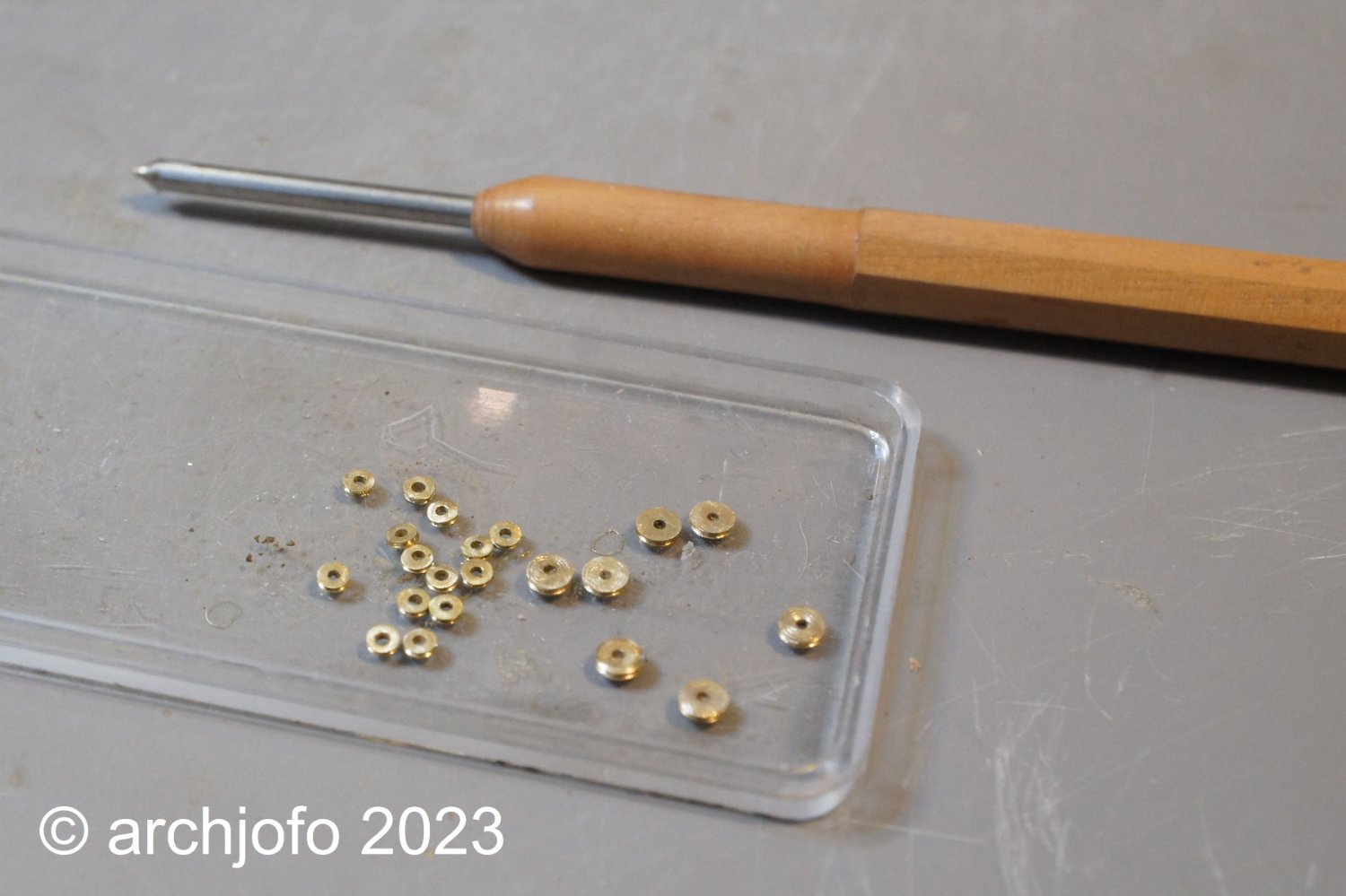
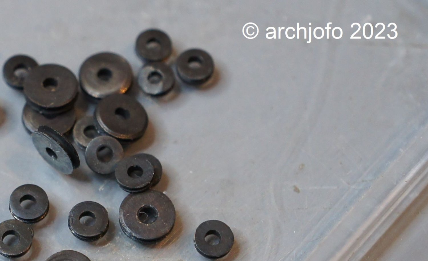
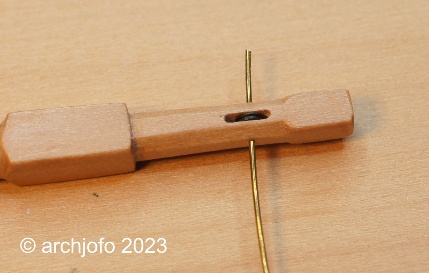
@tlevine Hi Toni, thank you for your interest in my construction report and the appreciation of my work. Many thanks also to the others for the many LIKES. Continued: Equipment of the yards As announced in the last part of my construction report, I equip the larger yards with real discs. As before, I make these discs out of brass and blue them. As far as I know, these discs were usually made of lignum vitae. The rather dark brown coloring of this wood can be easily imitated with a blue finish. For the main yard and the fore yard, the sheaves have a diameter of 2.9 mm. The main topsail yard, fore topsail yard and mizzen yard are fitted with sheaves with a diameter of 2.0 mm. With the following series of pictures I would like to illustrate how I make the sheaves. Since my turning skills are limited and with these small diameters, I made the circular groove with a jeweller's saw. The fine saw blade I use for this has a thickness of 0.15 mm. I can control the width of the groove. The more inclined I lead the saw blade, the wider the groove. As a rule, the groove has a width of around 0.2 mm. After cutting the sheaves, I grind them to the required thickness according to the size of the protrusion for the sheaves, i. H. about ø 0.6 mm or 0.8 mm. For grinding, I made myself an aid, the tip of which engages in the axle hole and thus enables the sheaves to be guided more or less evenly for grinding. The axle bores of the sheaves were made with ø 0.8 mm larger than the axle diameter ø 0.4 mm itself. This makes the installation of the sheaves much easier and also compensates for small inaccuracies. The next pictures should give an impression of the installation of the sheaves. As can be seen in the second picture, the axle holes are not exactly opposite. This is due to the fact that I have to drill the ø 0.4 mm holes for the axles from each side. If you try to drill these holes in one go from one side, it can easily happen that the hole on the other side does not arrive in the middle due to the thin drill and other inaccuracies. This is then much more disturbing than the axis points that are not exactly opposite, which is no longer noticeable after the shortening anyway. After shortening the axles, the ends are filed clean with a micro file and blued. The filing creates a small burr, which usually makes it no longer necessary to glue the axles. The last picture shows the finished yardarms of the fore yard, main topsail yard and mizzen yard. It then continues with the stunsail boom irons. There are still a few open points to be clarified, as always... 😊 Sequel follows …


-
Brig Le FAVORI 1806 by KORTES - 1:55
archjofo replied to KORTES's topic in - Build logs for subjects built 1801 - 1850
Fantastic work ! -
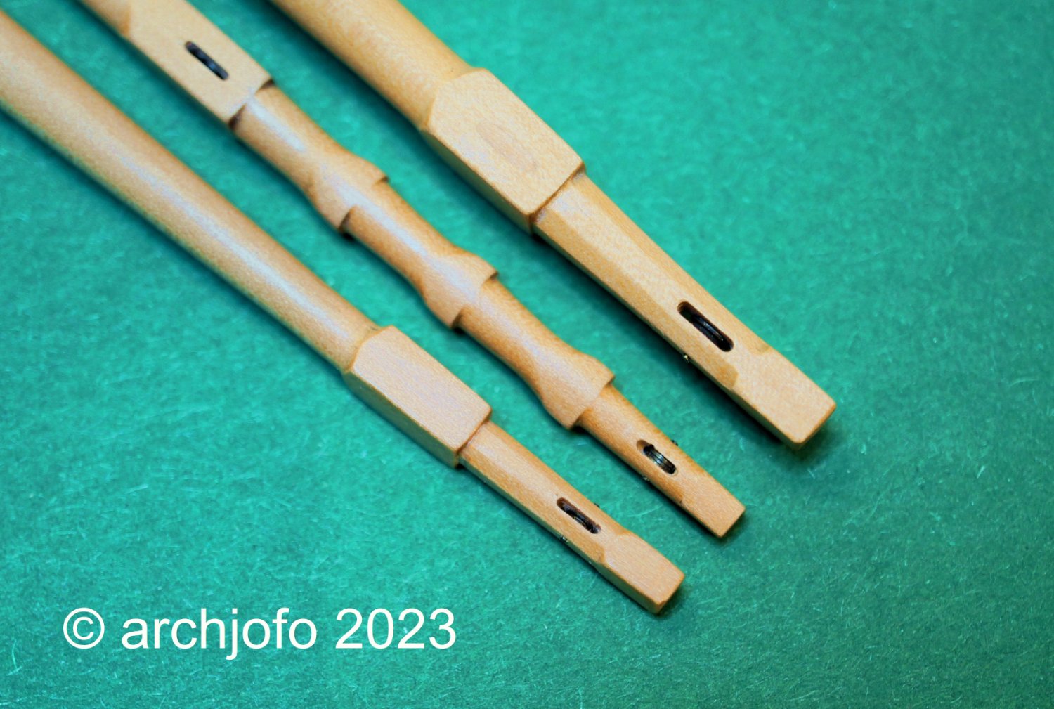
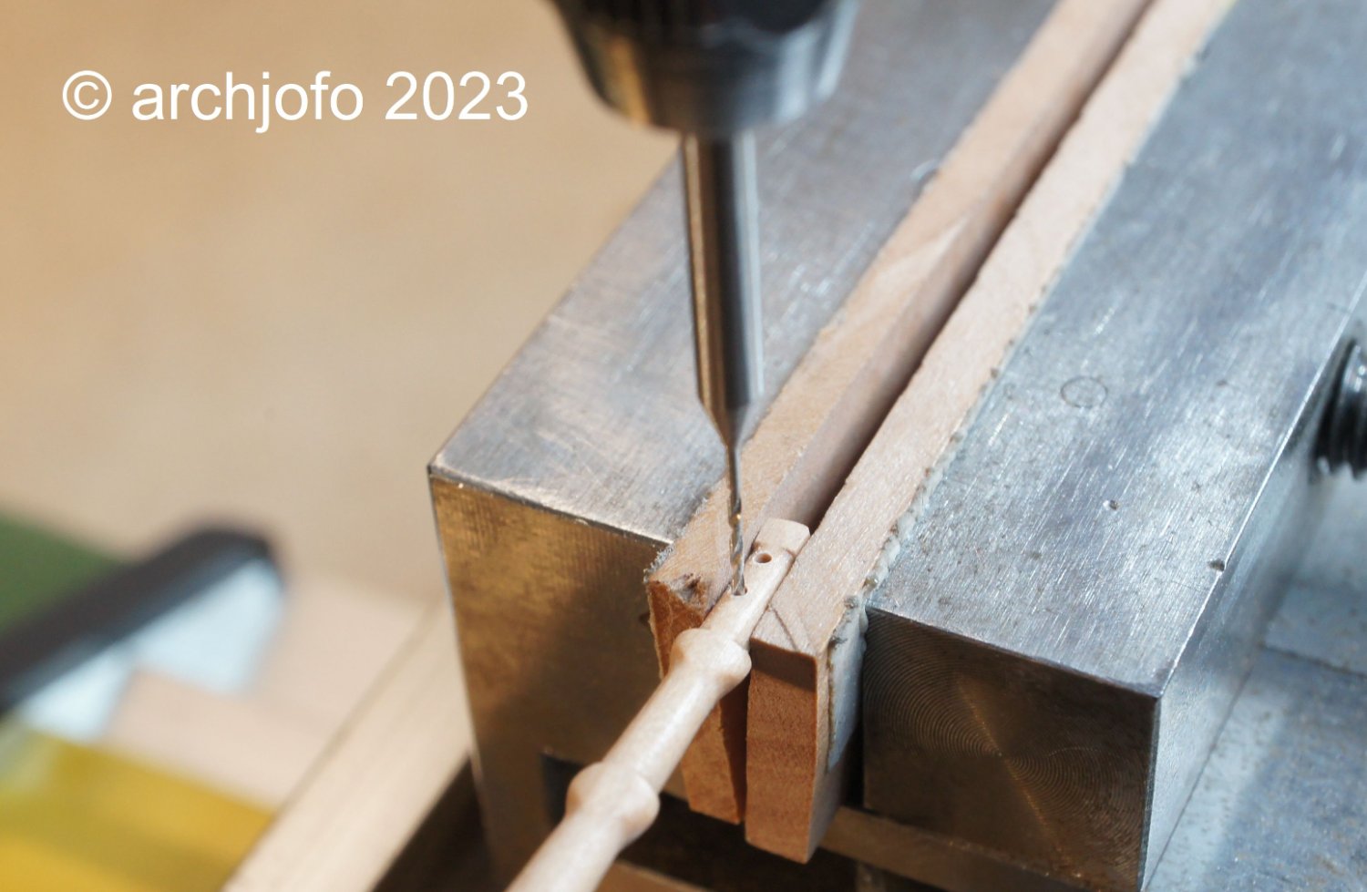
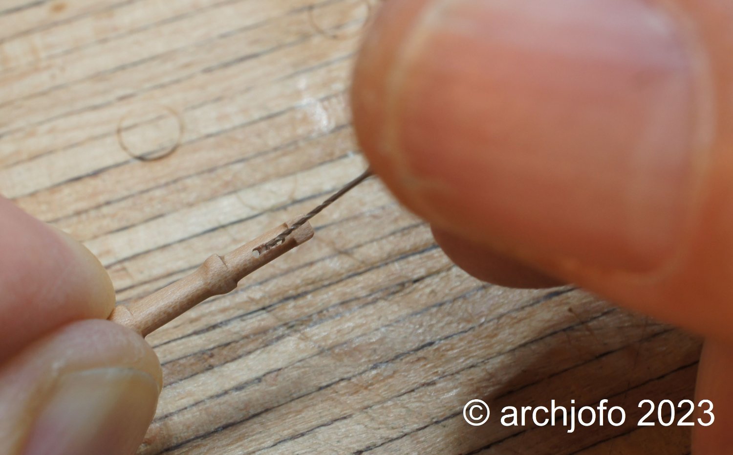
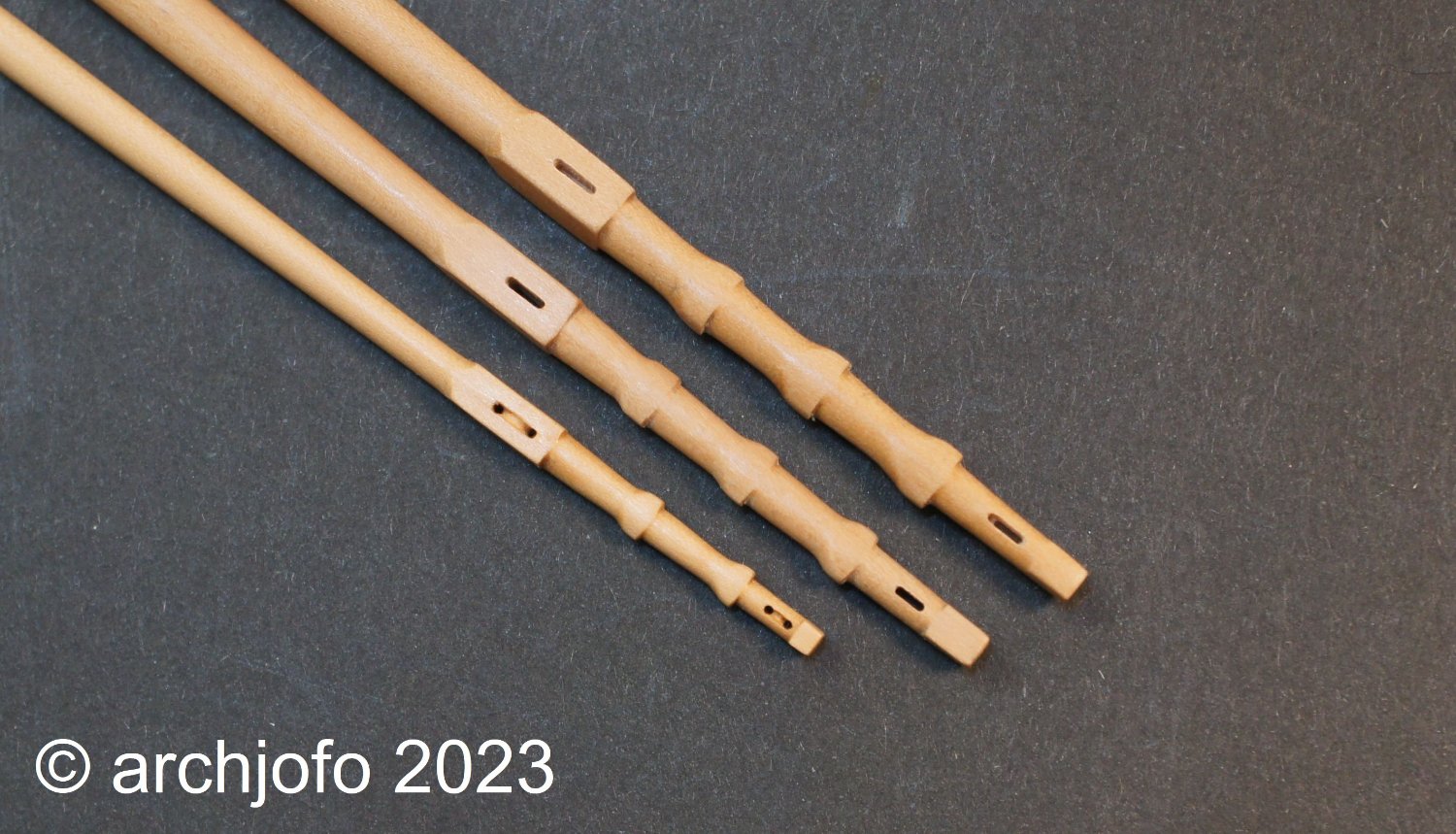
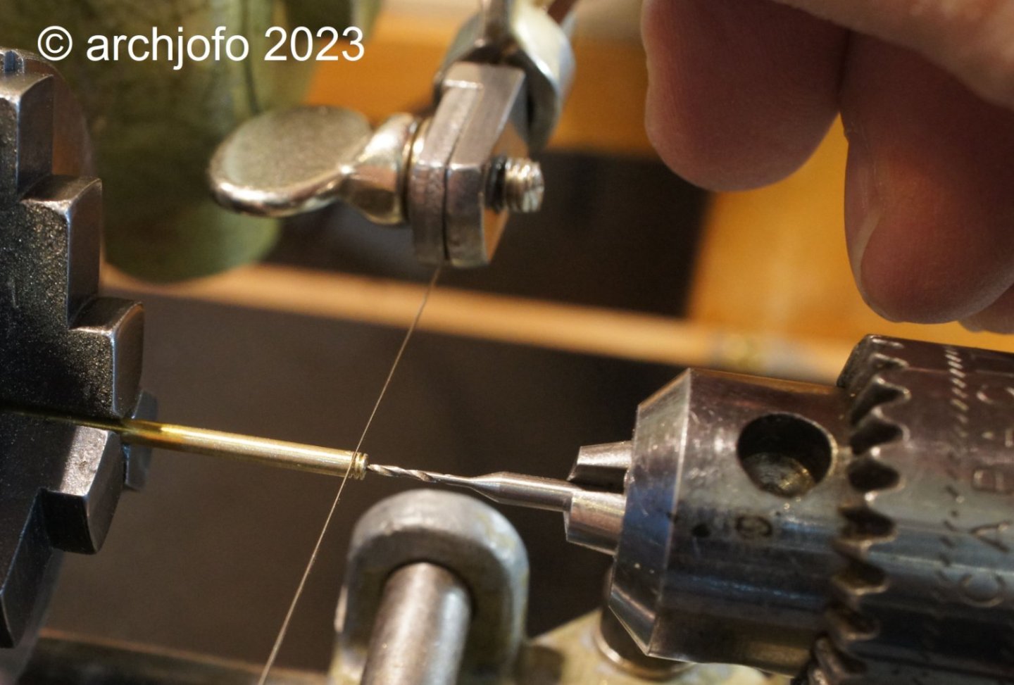
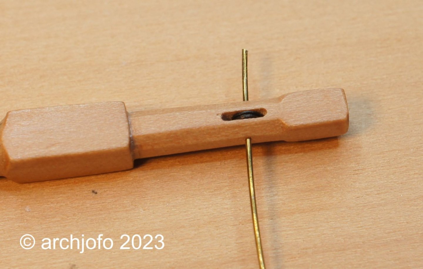
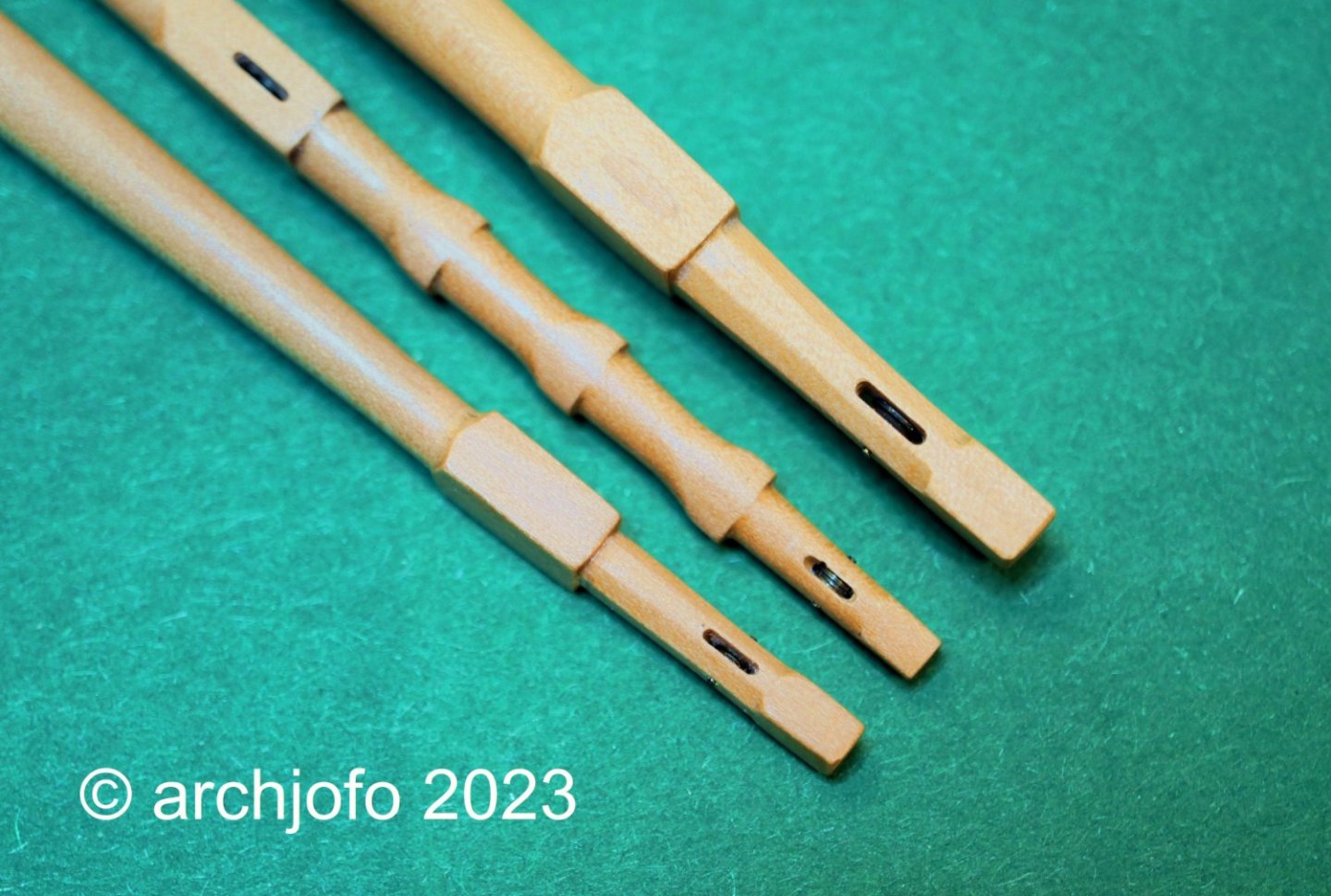
@AJohnson @jfhealey @hollowneck Hello, Thanks for the positive comments, also for the many LIKES. That motivates even more. Equipping the yards In the meantime, I have started to fit the ends of the yards with sheaves, over which the sheets and reef tackles are then passed. In the lower and topsail yards, the holes for sheave were made with the 0.8 mm and 0.6 mm milling cutter, with the exception of the mizzen topsail yard. Brass turned sheaves will be installed there later. For the topgallant and royal yards with the mizzen topsail yard, the sheaves are only suggested due to the size. The following pictures show the individual processing steps. 1. drill holes with 0.5 mm 2. finishing with 0.5 mm wood hollow chisel 3. rounding out with 0.5 mm shank drill bit The last picture shows the yard arms of the main topsail, fore topsail and mizzen topsail yard. I think that the "fake" sheaves in the mizzen topsail yard are reasonably convincing. I have also used the same method on many blocks. See you soon ...


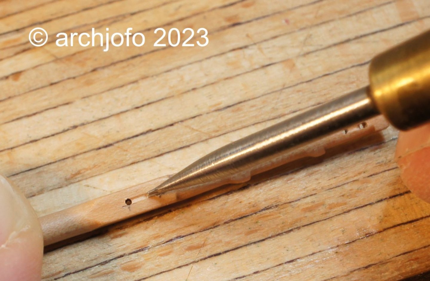

.jpg.6a154bd65a09a952fd1cdb06bfa12417.jpg)