HOLIDAY DONATION DRIVE - SUPPORT MSW - DO YOUR PART TO KEEP THIS GREAT FORUM GOING! (Only 53 donations so far out of 49,000 members - C'mon guys!)
×


ianmajor
-
Posts
784 -
Joined
-
Last visited
Content Type
Profiles
Forums
Gallery
Events
Everything posted by ianmajor
-
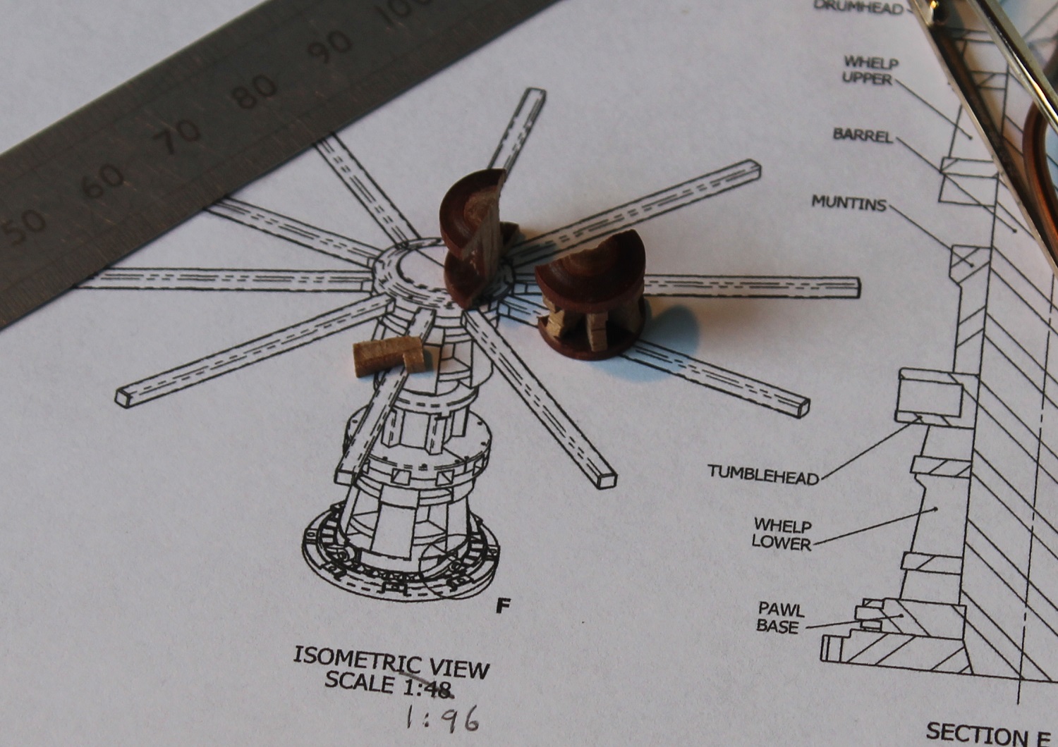
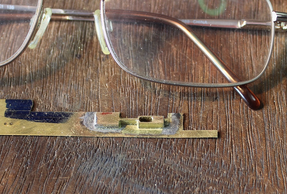
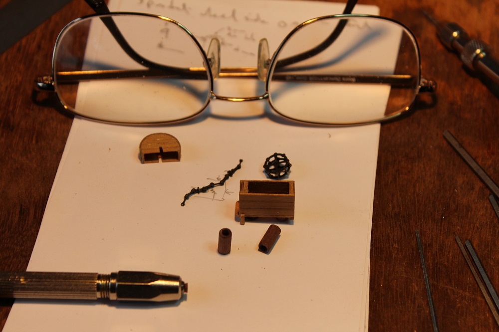
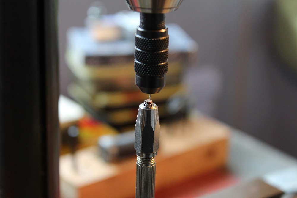
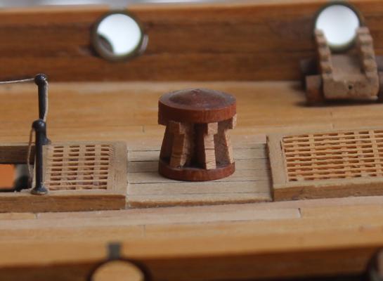
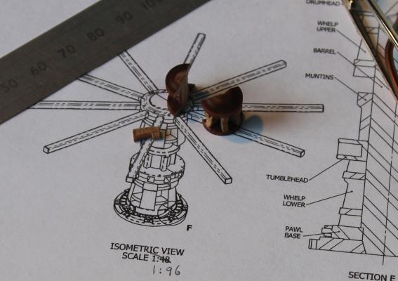
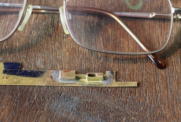
 David, thanks for looking in and for your comments. Mark, The height of my belfry was giving me pause for thought when compared to the rails. I was beginning to think that I would have to make a bigger one and donate this one to someone who is making a 1:96 scale ship! But I had a good look at the Lyme plans and found that the belfry shown there was in deed only just over 3ft tall. I have attached an extract from the Lyme plan with the scale (in feet) shifted alongside the belfry. The black arrow indicates the top of the belfry, the red arrow the deck line. The belfry does look tiny, so whilst contemplating the rails on either side of it I turned my jaundiced eye to another item that needed improvement. This would be a quick job. Some of the most distinctive things on a capstan are the holes for the capstan bars. The Corel offering has none - which can be seen from the photo. It also has rather a domed top. I decided to slice horizontally through the top add a layer of wood, cut some radial slots, then reattach the thinned down top. First I skimmed down the domed top in the lathe. Sadly, despite my taking the smallest and slowest cuts, the tool dug in, there was a snick sound and the result......... Did I say this would be a quick job? OK....Plan B. I reached for some more of Rex Boocock's plans in the reource section. Capstan plans to 1:24 scale are <here> I have started to scale the plans for 1:75. The resultant capstan will be about 20mm diameter and about 18mm tall. This is larger than the Corel offering which is 12mm diameter and 12mm tall. Rex shows each part of the capstan with 5 whelps. Other capstan models I have seen with this number and some with more. He dates his plans as post 1780 which is late for Unicorn. He also states that the sizes were taken from HMS Pandora which should be OK for Unicorn. There are articles on capstan construction in the resource section. A very good one by Allan Yedlinsky is <here> There is also a digest of capstan articles pulled from MSW <here> including a warning from Decoyman about wrecking one's capstan in a lathe! Onward and upward.......
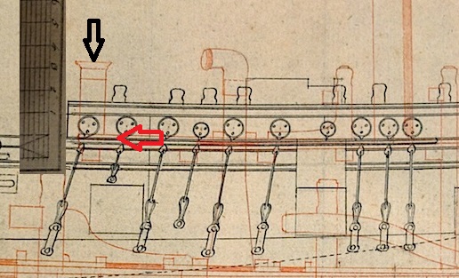
-
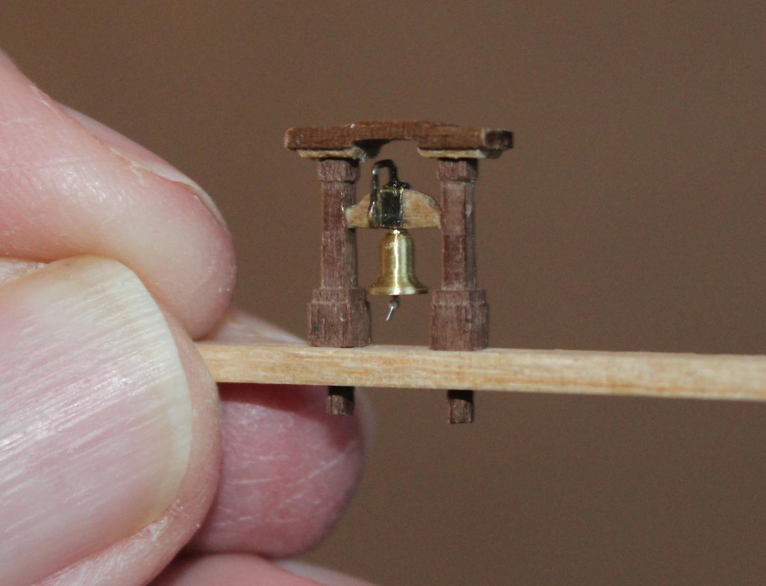
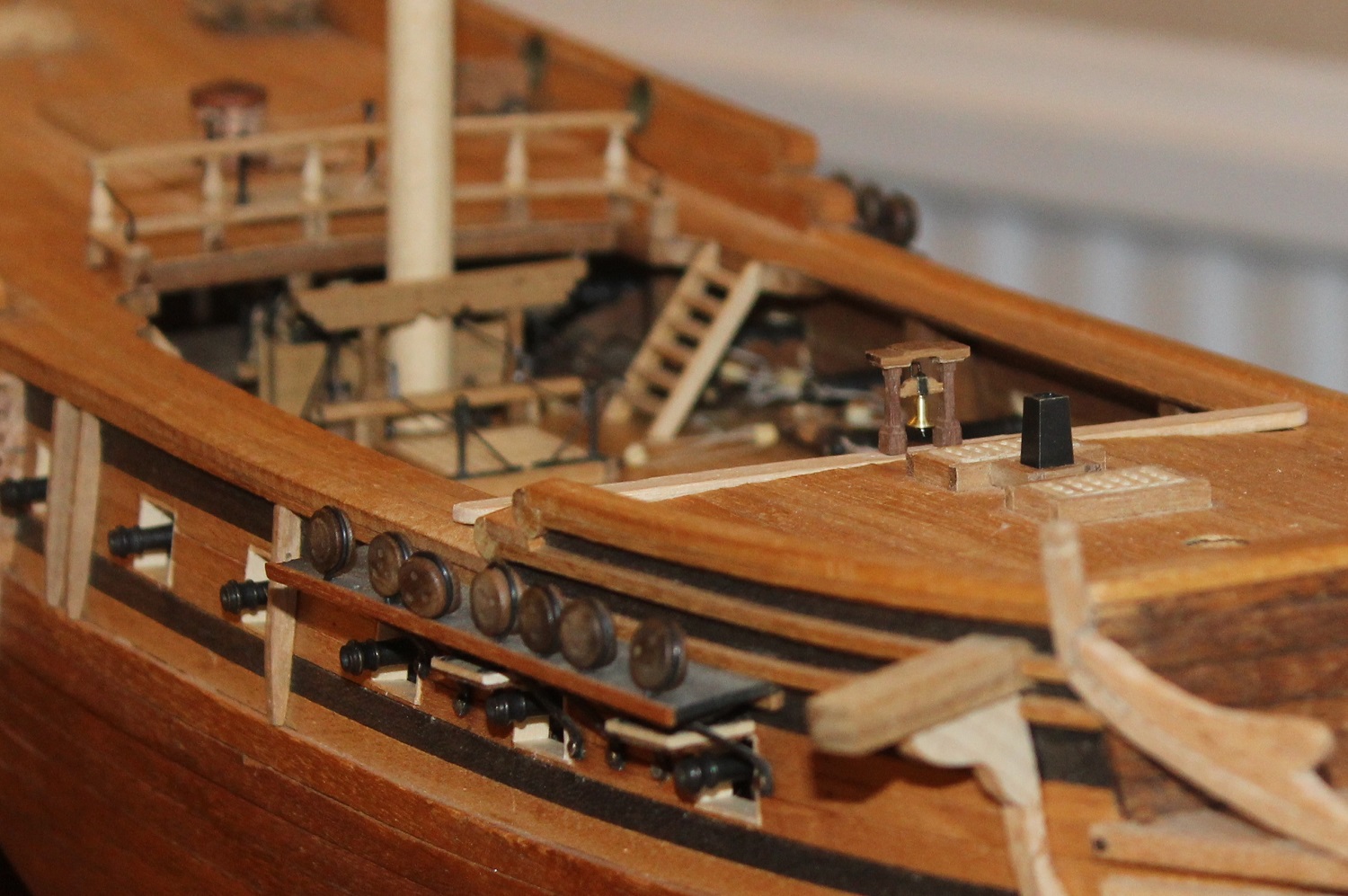
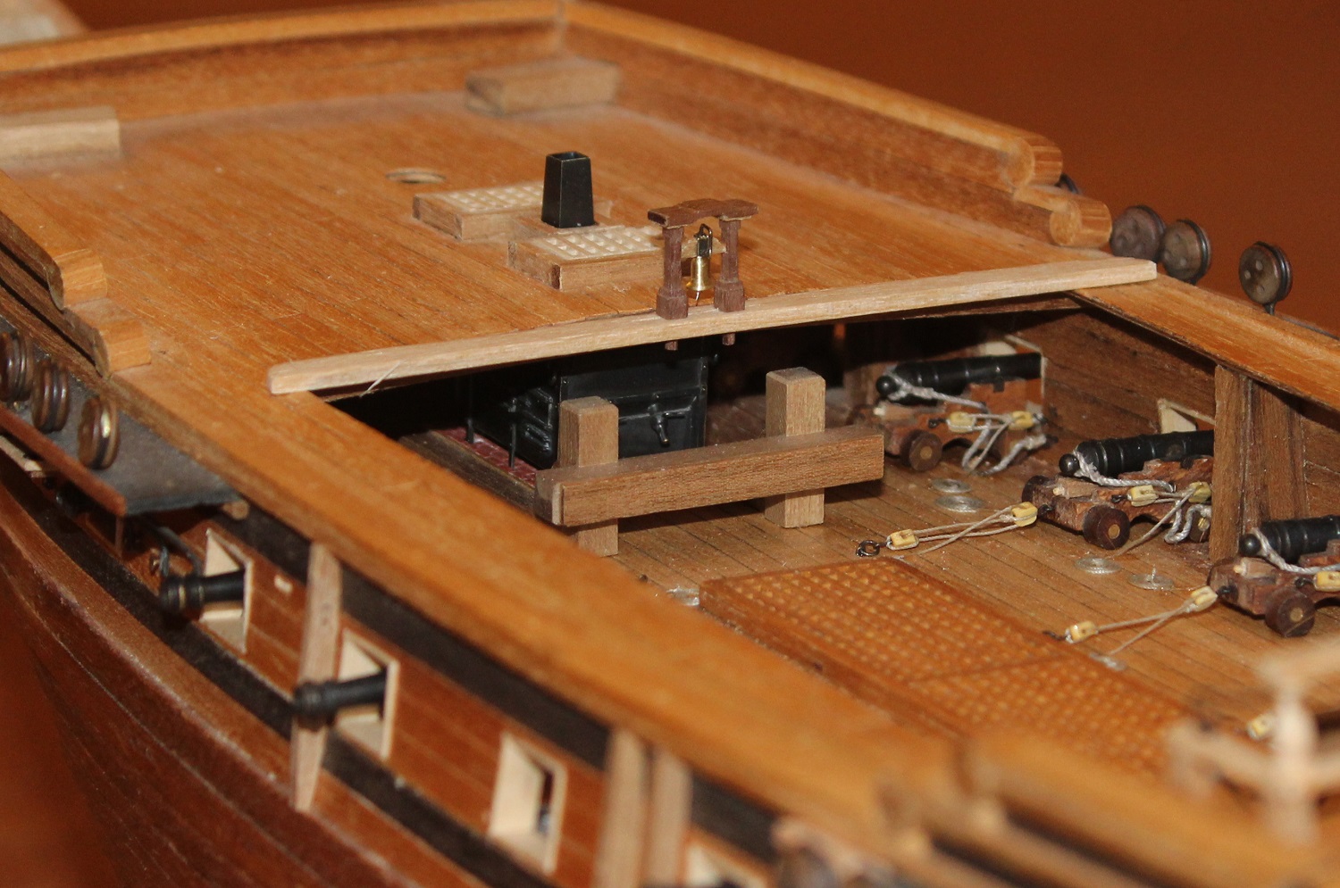
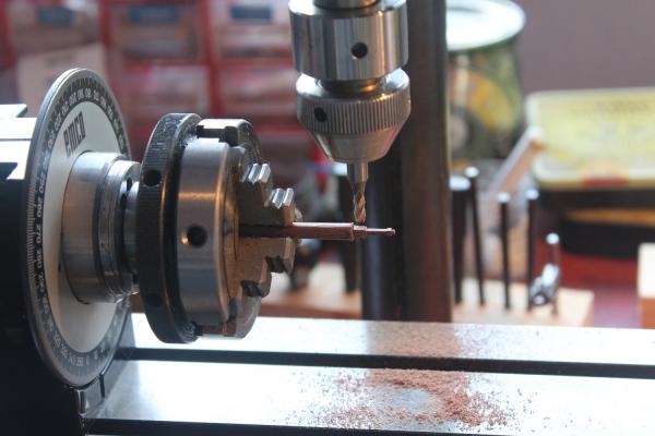
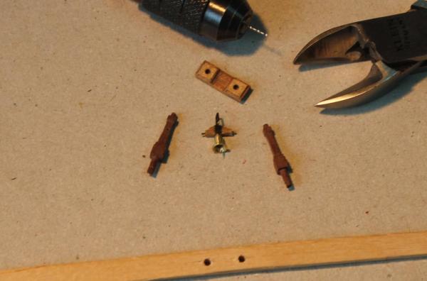
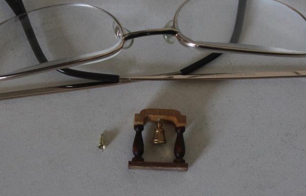
Piet, Thank you for your kind words. Your 0 19 looks wonderful. I am one of those who, for selfish reasons, is sad to see it finished. I was enjoying the construction so much. Mike, I would be surprised if Corel were the slightest bit interested in photos from me. I believe they started making ships' kits circa 1971 and the Unicorn kit was designed 1974 so was one of their first.They would have little interest in latter day work! Grant, I have to admit that milling walnut gives me the ebie jeebies. I am constantly expecting the detail to disintegrate in front of my eyes. I varnish the piece before milling to try to prevent this. That does introduce its own problems with the effectiveness of glues of course. So I milled a couple of supports in the walnut. A straightforward if small milling job using the dividing head. Each support is rectangular in cross section. The wider sides are taper which makes it a little more challenging. The tops were turned 1mm and the bottoms 1.5mm. The head of the belfry was also milled in walnut. Two rectangular pads of thin walnut were glued to its underside then two 1mm holes drilled to take the uprights. I had decided against using the styrene version even though that one had more detail. I did consider adding a layer of thin card on top of the walnut head to give a little more overlapping detail. This would have to have been painted which I thought would not look too good. The headstock also was milled from walnut. A strip of blackened brass shim was folded over the top. It should taper towards the bottom but at this scale the taper is only about 0.1mm on each edge - difficult to get an even result - so I used strip 1.2mm wide rather than tapering from 1.4mm. The top was drilled 0.4mm in the centre to take a blackened piece of 0.4mm brass wire bent to represent the crank. The ends of the headstock were drilled 0.4mm to take short pieces of wire to act as pegs to locate it in holes in the uprights. The next photo shows the components awaiting final assembly.The piece at the bottom is a temporary base drilled to match the spacing of the holes in the head. The components were finally assembled using the temporary base. It is certainly smaller than the Corel offering. It scales out at just over 3ft tall by 3ft across the head. I think I have scaled it correctly from Rex's plan. Unfortunately there are no leading dimensions or scale bar on the plans to cross check against. Does anyone have any views on the size of actual belfrys on frigates as opposed to the size supplied in kits? Here is a copy of Rex's plan on which I added scale sizes in millimeters. I tried the belfry in position on the Unicorn and took a couple of photos to see how it looked. Any thoughts on its size when it is in place?


-
Paul, That is a big improvement over the kit offering you have produced. I think the Manchester air (or possibly rain) must be conducive to excellent model ship building.
- 708 replies
-
- 3
-

-
- victory
- constructo
- (and 1 more)
-
Dafi, Interesting. I have seen references to the fact that sailing ships would take hours to maneuver in to position to engage other ships. I can see from your work and research that whilst this was being done a similar length of time would be needed to ready the decks for action. To be able to observe this must have been like watching a disturbed ants' nest!
-
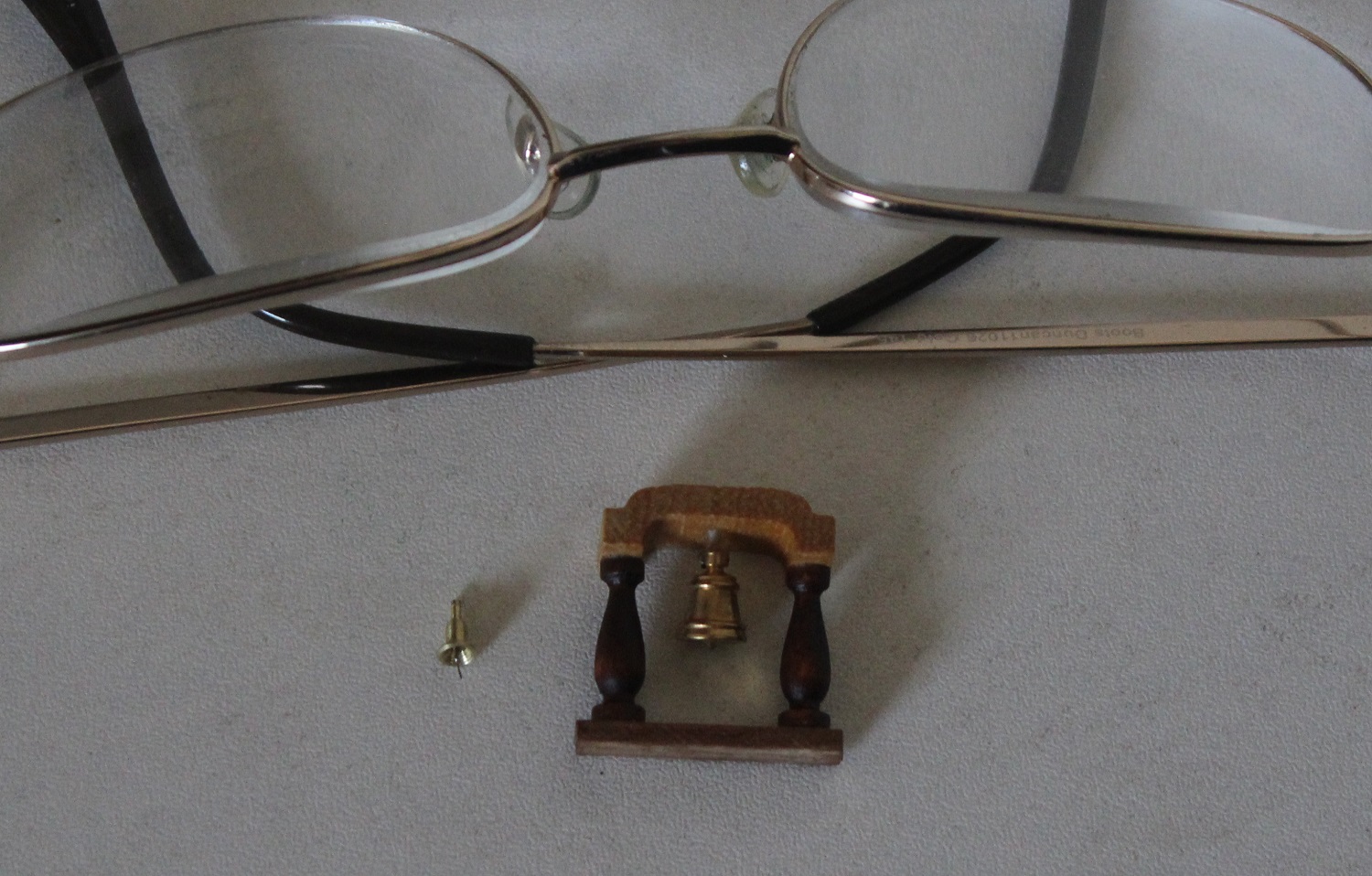
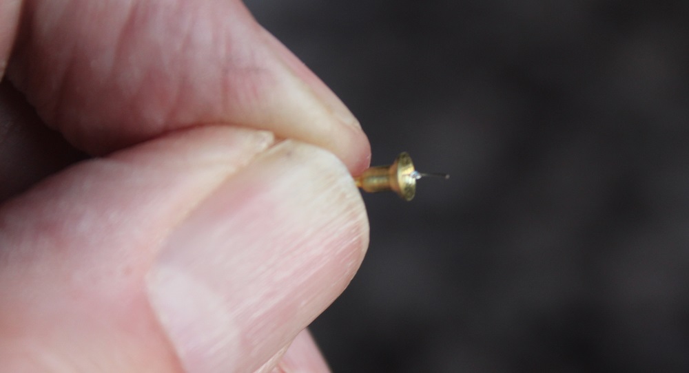
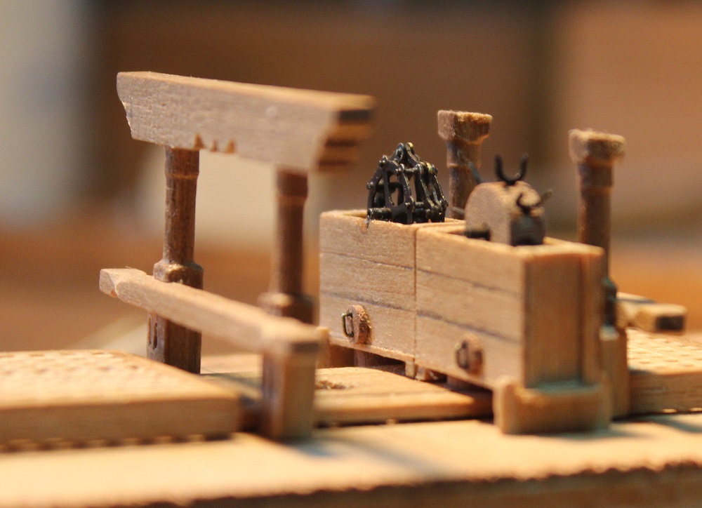
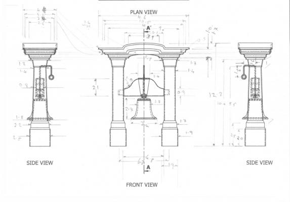
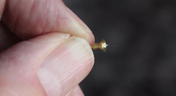
Grant, Dafi, David and Joe thanks for your kind words and thanks everyone for the likes. I have decided to tackle the belfry first. I am using the plans produced by Rex Boocock which can be found in the MSW resource area <here>. Rex's plans are 1:12 which I printed out full size then any measurements taken from it were multiplied by 0.17 to get them down to 1:75. The first thing that this revealed was that the belfry made with the Corel parts is, in deed, much too large. It stands a scale 6ft+ tall and the bell scales out as (aprox) 2ft in diameter and 2ft high which I think would be more at home in a church bell tower. The ships bells that I have seen details of are nearer 7 to 8 inches in diameter. So I machined one from some brass rod. I end drilled it 1.5mm to a depth of 2.5mm followed by drilling 0.5mm for a further 5mm. The mouth of the bell was then formed and tapered by drilling shallow holes with large bits then tidying it with Swiss files. The outside was turned to shape leaving a 1mm diameter spiggot at the top for fixing the bell to the belfy. When cut off this spiggot had the 0.5mm hole through its centre. The clapper was made from the core of instrument wire. I tied a knot in it and then touched knot with the hot iron with the tiniest ammount of solder on it. One end of the clapper wire was fed through the 0.5mm hole then fixed with solder applied to the end. The photos show the new bell next to the Corel offering and a close up. I am trying some experiments in constructing the belfry cap which is quite decorative. My first attempt is using layers of styrene sheet. This is made up of 16 parts. The down side to using styrene sheet is that I will have to paint it. So I will be having a crack at milling a cap from walnut for comparison. Boxwood would be better but I don't have any. I think (hope) the parts so far are coming out the right size!

-
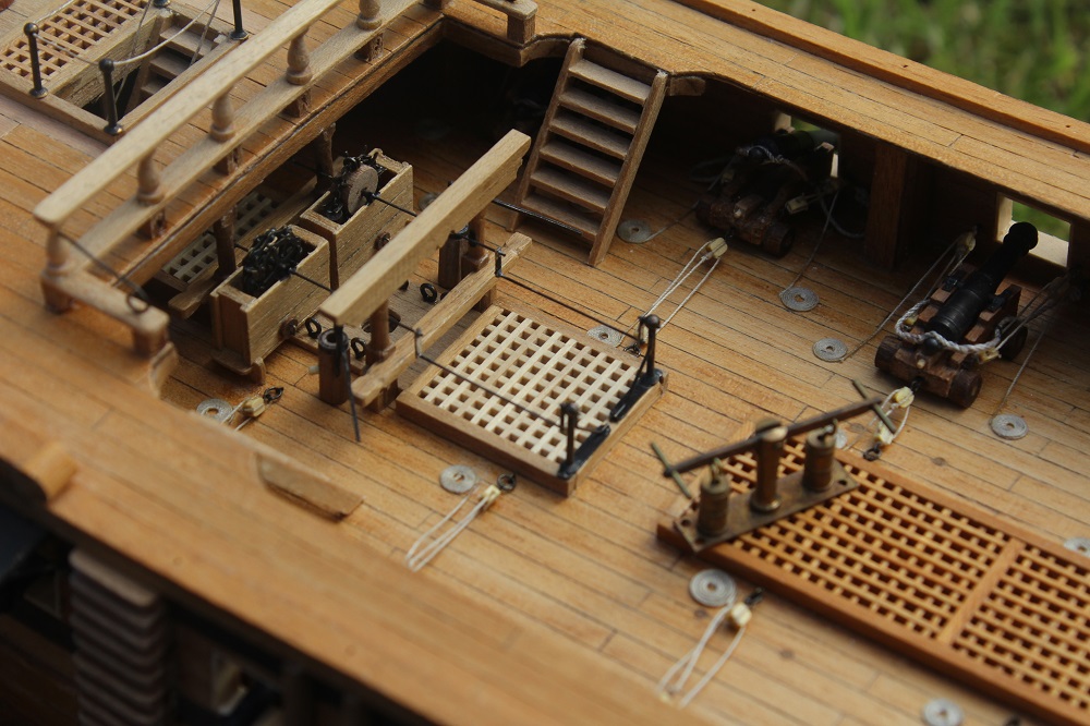
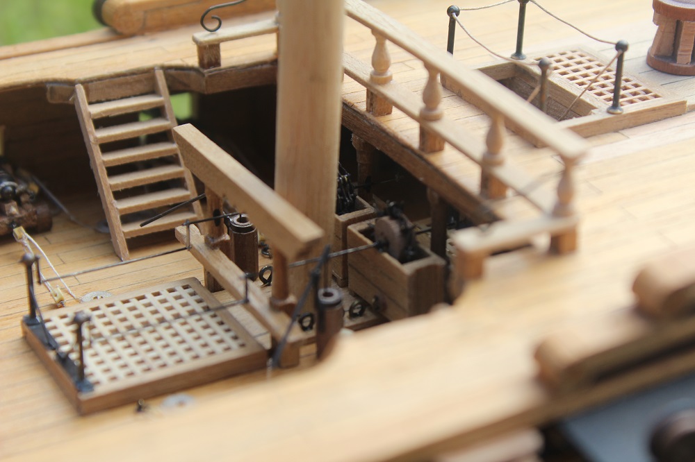
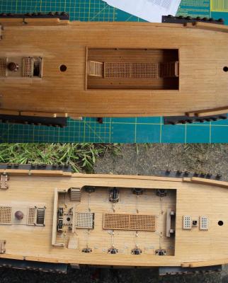
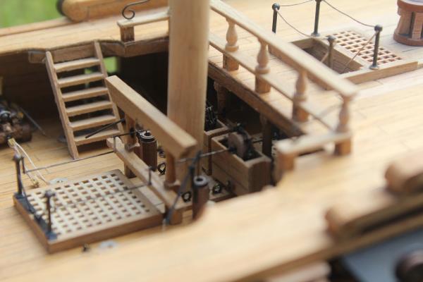
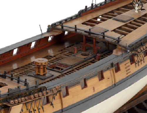
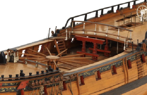
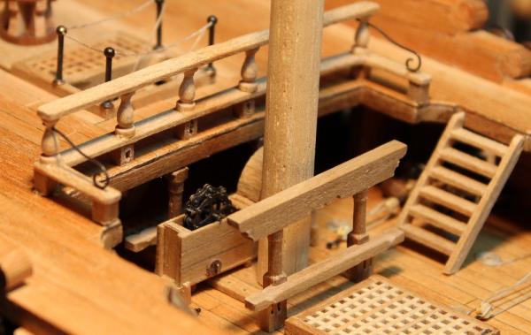
Nenad, thanks for looking in and for your comments. And guys thanks for the likes. I made some final adjustments to the pump parts then installed the pump sub-assembly permanently in to the waist area. A few photos. The first shows the sub-assembly in place with the elm tree pumps fitted. To the right of the photo is the superseded pump that was supplied with the kit - it is, in my opinion, a 19th century design so is a 100 years too late for this Unicorn. An opposite view with the stub mast in place. I cheated with the rhodings - these are simply rectangular blobs of thick black paint. A couple of before and after shots. The first is looking across the waist area towards the stern. The left half is as it was being built as per the Coral plan. The kit supplied pump can be seen towards the rear of the quarter deck. An unlikely position since its tubes would have gone straight down in to the captain's cabin - hum. And would you really position your pumps on the highest point on the decks simply to shoot the water in to the sea? This would be rather a waste of effort methinks. If I remember correctly Peter Visser on his Unicorn re-positioned this pump on to the upper deck just behind the main mast. A simple and effective modification. The second is the view straight down on the waist area. The upper view is the original. I think the modified version looks better. One problem. The original woodwork was varnished more than 30 years ago and has darkened with time. I have used the same varnish on the new woodwork and am hoping that in time it will darken to match. Well, at long last, that is the waist area finished (I think). Time for me to climb out and revisit the fore and quarter decks. Now where to start....? The oversized belfry comes to mind, possibly improve the capstan, or perhaps a binnacle . This will all be playing with wood which is right outside of my comfort zone - so I will be struggling (again) .
-
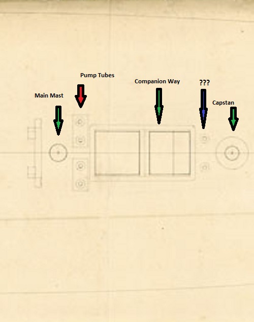
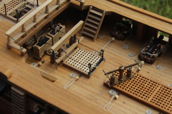
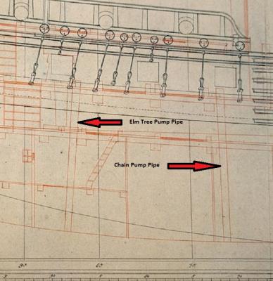
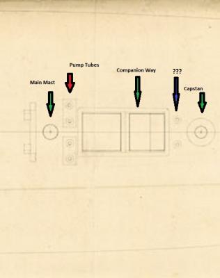
Hello Dafi, Actually many of the ideas I show here are borrowed (stolen?) from your Victory log then modified. The world of model making at its best is like a reverse version of the children's party game pass the parcel. In that game the parcel is passed around and each child takes a layer of wrapping off. In modelling someone comes up with an idea passes it on, the next person adds to it passes it on and so on. When it gets back to the guy at the beginning he sees a version that is sooo much better than his original. Mike, Thanks for your input. I wondered about the two items ahead of the capstan. I thought they may well be elm tree pumps but was concerned that that position would interfere with the operation of the capstan. Looking at the Lyme elevation plans I can see the tubes for the chain pumps descending to the bowels of the ship just behind the main mast. There also appear to be tubes just ahead of the capstan suggesting this is the correct position for the elm tree pumps. Extract from Lyme plans with my interpretation annotated : I had already committed to fitting the pumps slightly ahead of the main mast - 2mm holes drilled in the deck in readiness - based on Chuck's Winchelsea layout. A trial fitting does produce a rather crowded grouping. Winchelsea is a slighter larger ship than Unicorn/Lyme. Perhaps I should have looked more closely at the diagrams and dispensed with the elm tree pumps. Still they look quite pretty. Whilst I was researching the Elm tree pumps I found information about Gosport and Portsmouth (UK) fresh water supplies. Around the year 1700 the water companies started laying underground water pipes made from bored out elm tree boughs. The Portsmouth Water Company had a photo on its Web site showing one of these pipes being lifted in the 1930s as part of an upgrade to the water supply. The elm pipe was in remarkably good condition. I was going to put a link to this photo but sadly the Water Company has "improved" its Web site and the photo has gone. No doubt it will pop up again somewhere.
-
Grant, ZyXuz, Piet and John many thanks for your kind words. John, Thanks for the holiday wishes. I will probably spend much of it fiddling with the Unicorn! You make a good point about the types of pumps on English 5th and 6th Rate ships in the mid 18th century. I had look at the photos of the models in the NMM. The best photo of the one that you referred to (SLR0497) can be seen <here> . I have taken an extract of it: There is another 1757 Warship model (SLR0496) which can be seen <here> on which the pumps can be seen more clearly. As you say only elm tree pumps are visible. An extract of that one: The Chapman diagrams do not help. However I looked again at the NMM held plans for the Lyme (the Unicorn's sister ship). I have annotated an extract of the upper deck plan: Behind the main mast marked by a red arrow is what I interpret as the two pairs of pipes and cisterns for chain type pumps - but no sign of elm tree pumps. There are other differences such as the capstans on the Lyme class are behind the main mast whereas the capstans on the Richmond class (in the above photos) are in the waist area. Confused? I certainly am.
-
Gaetan, As ever your work is fabulous. On the print icon issue have a look towards the end of the thread <here> . The print icon only appears on logs of 20 pages or less, it is a "feature". There does not appear to be a fix for this.
-
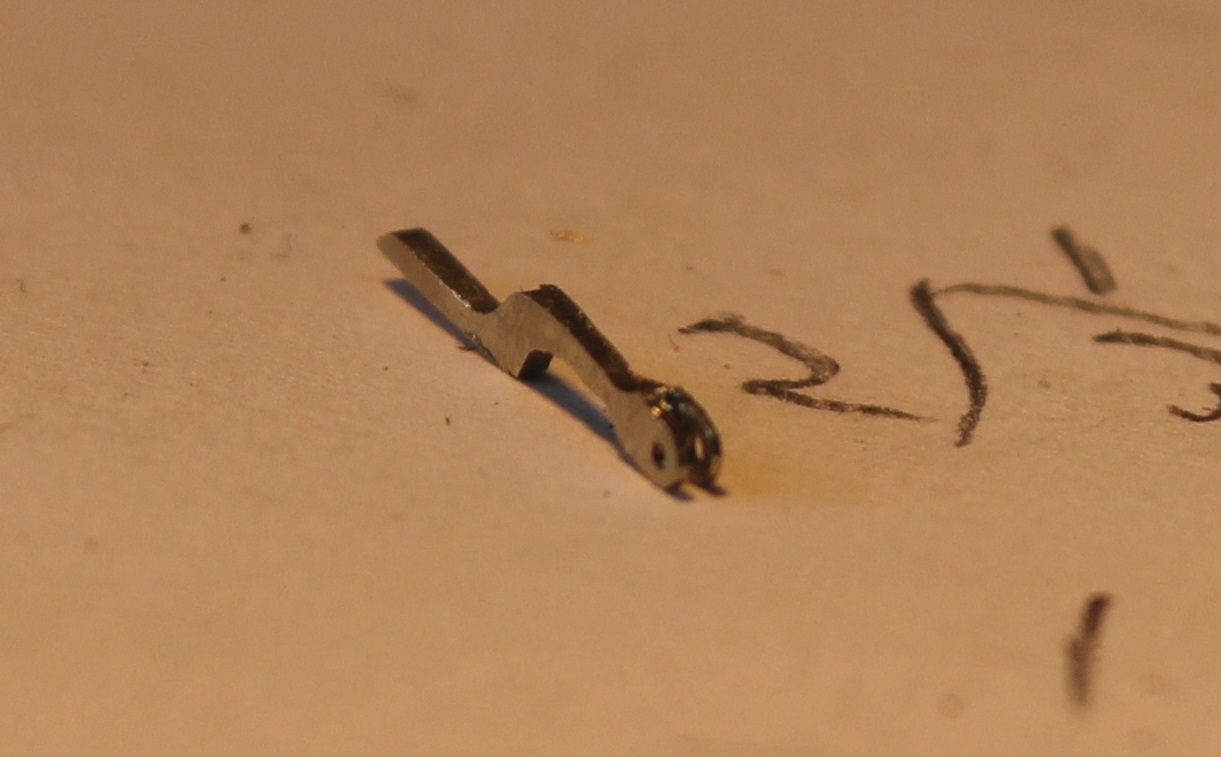
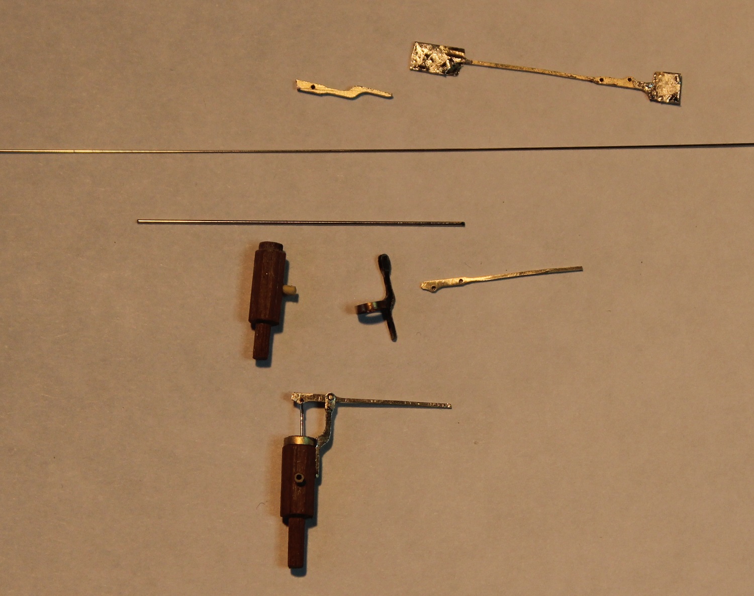
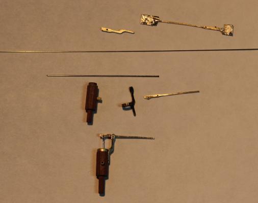
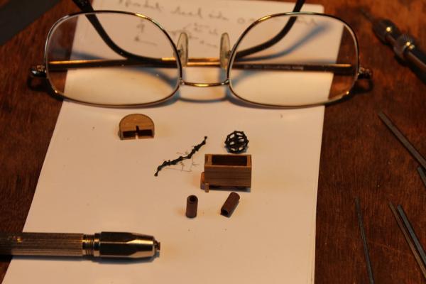
Three lengths of 1mm thick N/S were tacked together and then drilled and milled to make the handle brackets. A slot was sawn in the end of each piece to take a handle. The best two brackets were then each soldered to a ring. Three pieces of 0.5mm N/S were tacked together and drilled/milled to make the handles. The next photo shows the various stages. At the top are the blanks produced by milling. The middle shows the blanks filed to final shape. The bottom is an assembled pump. A final photo shows the pump in my agriculturals for scale. The handle wiggles up and down! The metalwork is still to be blackened, then after some final adjustments the whole pump cluster will be ready for permanent installation in the waist area.
-
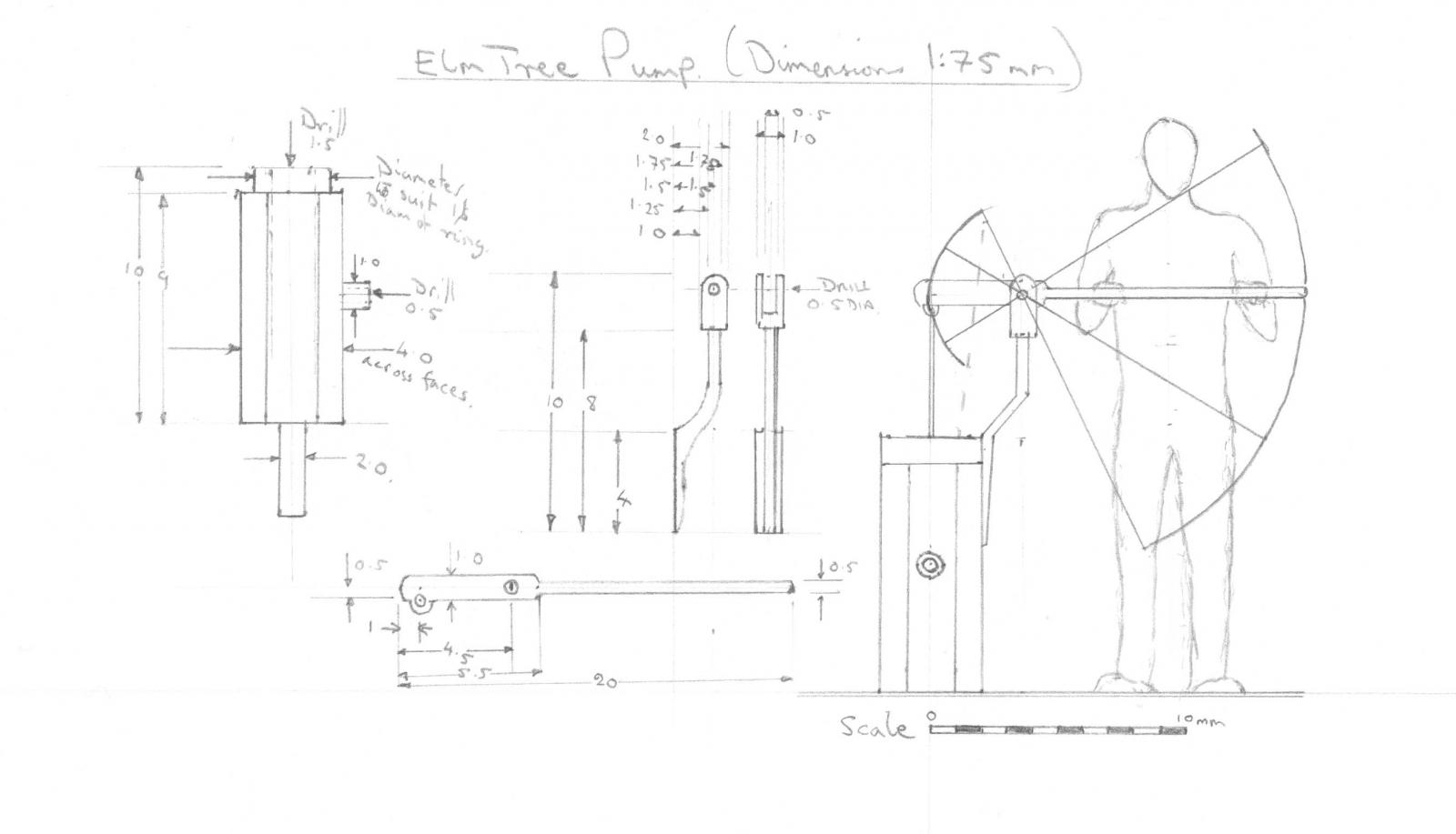
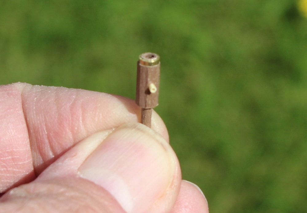
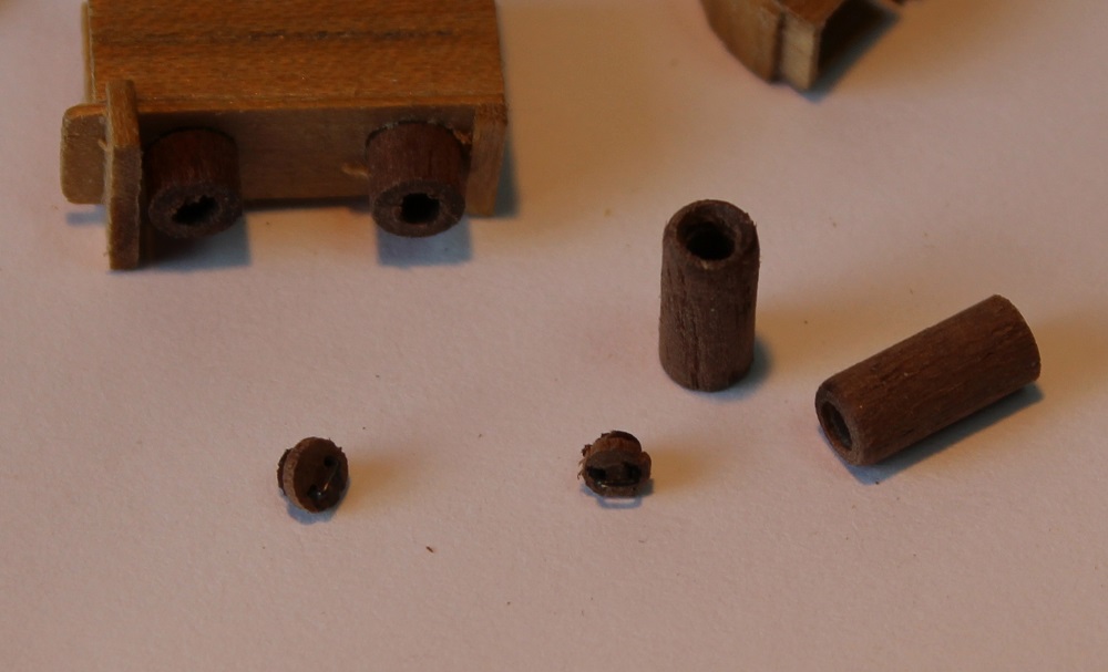
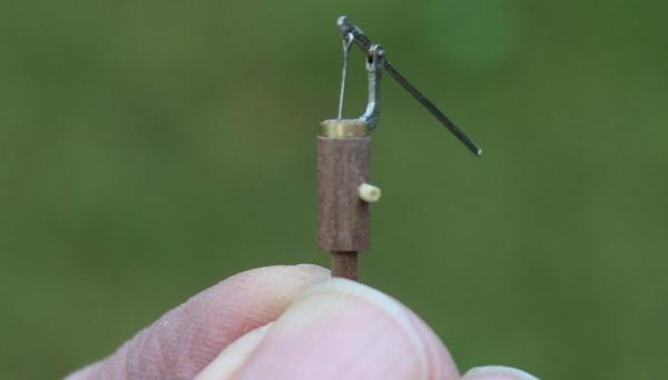
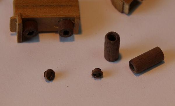
David, Nils and tuciship, thanks for looking in and your comments. (Hopefully I have put this in the correct log this time - what a plonker!) Now to start on the elm tree pumps. Information came from several sources. The dimensions I got from Lavery. I produced a scale diagram. On the diagram I included a 5ft 8in sailor to make sure the size was sensible. The first items made were 1mm wide rings cut from 4mm diameter brass tube. I produced these first so that I could use them as gauges when turning down the wooden "pipes". The pipes were produced from walnut dowel. The end was turned down so that one of the rings was a good interference fit. With the ring in place I end drilled the dowel - the ring stopped the wood from splitting whilst drilling. The dowel was transferred (still in the chuck) to the dividing head mounted horizontally in the mill to make the main part of the tube an octagonal shape. Then back to the lathe to turn the bottom to 2mm diameter. A short length of bamboo was end drilled 0.5mm then turned down to 1mm outside diameter. This was set in to a hole in main pipe as the outlet.


-
Piet, A nice finishing touch, though as you indicate there may be a few bits and pieces that will attract your attention. I am really pleased the way the project turned out which produced a wonderful result - and thanks for sharing the progress with us. All the best...
-
Ah at last - a photo that I have been waiting for - the proud owner with his completed creation. It gives a good idea of the scale of the work. I suppose I am a bit old fashioned in that I like seeing the modelers - preferably in the flesh where possible. Thanks Dave for publishing.
-
Daniel, Absolutely fascinating. I can see plenty of jobs there that risked trapped fingers and limbs. BTW I am a great believer in understanding how things actually work when making models. In my view it leads to better modeling - which your fantastic models clearly show.
-
John and Grant, thanks for your kind words - I fear you see a better standard of workmanship than I see. I keep looking and thinking that I should have done better. Thanks guys for the likes. A quick update. I have been consulting the on line copy of Thomas Oertling's Thesis for my info. This is dated 1984. His book on the subject of ships' pumps was published in 1996. Obviously he had done much more research for the book. I had a look at a preview of his book which included a part of the chain pump section. In this he states the valves/saucers were about 50cm apart on the old type pump chains. This scales down to 6.7mm in 1:75. I measured mine - the pitch of my valves is 7.5 which is fairly close. I will leave them as constructed. Interestingly in his thesis there is a diagram of a wooden sprocket wheel on page 85 which has 8 forks. I have seen other similar diagrams which are probably based on a contemporary Dutch diagram of the pump mechanism of an early 18th century British 50 gun ship. However in his book (page 65) he has a diagram of his reconstruction from fragments of the chain pump on the Santa Antonio which has only 4 forks on the drum. Ho hum - yer pays yer money and yer takes yer choice! Either way I perhaps should have consulted a copy of the book before starting the pumps rather than after the event.
-
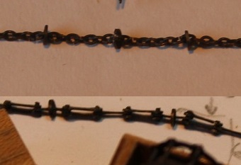
Next was the chain. I have a length of chain left over from that which I "knitted" for the rudder. This looked OK for the job. I cut some slotted discs in the same way as for the first pump. With a little sanding of the slots the discs slipped on to a chain link nicely. A touch of solder on the end of the slot kept them in place. The next photo is a comparison of the "old" style chain (upper) and the "new" style chain. The big question was/is - how many saucers and at what spacing should there be. I could find no clarification in Oertling or anywhere else for that matter. The entry in the London Magazine states that with the new pump 2 men lifted a ton of water in 55 seconds, however two men could not move the old type pump. This indicates to me that there was more friction suggesting the old pump had more valves (saucers) than the new. I was debating whether to have the saucers spaced to engage with every fork but decided to set the spacing at every other fork (OK this means that on a working pump every other fork would never get used). I did a dry run assembly to see how the whole thing looked and compared it with the first pump. Until I permanently fix the mechanism I could still add more saucers. I am inclined against this because both chains look a bit heavy to me and extra saucers would exacerbate this. If I decide that this is OK I will fit the mechanisms permanently and move on to some elm tree pumps.

-
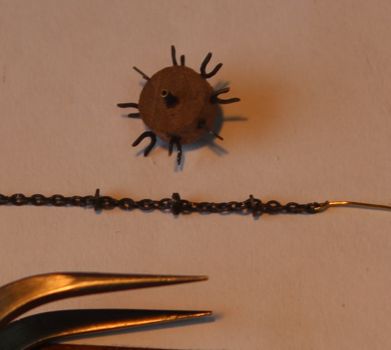
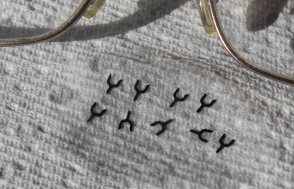
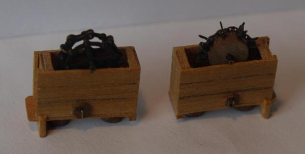
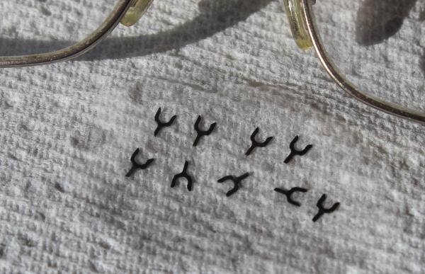
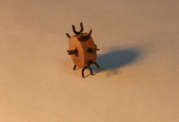
Thanks Mike and thanks guys for the likes. Well I have made some progress on the second chain pump mechanism. I am going with the early type of mechanism. I was interested in the references quoted by Oertling. One was an entry in the Setember 1768 London Magazine (or Gentleman's Monthly Intelligencer). Back copies of this news sheet are held in the Library of the University of Michigan. They have been digitised and the 1768 set can be found here Part of it is the "Monthly Chronologer" (basically a diary). In the September Chronologer (p499) sandwiched between lists of murders, robberies etc and the strange case of a sulphurous fireball in Devon is a brief description of the comparitive tests held between "Mr Cole's New Pump" and the old type pump on HMS Seaford. It includes some of the results. It only mentions William Cole not Captain John Bendinck who is credited as the inventor of the new type of chain pump. Cole would have been the man who realised the physical entity. I wandered off in to other sections of the London Magazine and found for example on page 328 reference to the discovery of a cluster of islands in the Pacific by the crew of HMS Dolphin. They named the islands King George Islands.Apparently the ship's crew found themselves pelted with stones by the locals so eventually the crew responded with cannon loaded with grapeshot. No contest from that point - but not a good way to make friends. The Magazine also includes articles about hostile French activity in Corsica. It is a great source (British view) of information on the various battles, developments, personalities etc on sea and land. The navy tests of the "cycle chain" type pump occurred in the last few years of Unicorn's existence so perhaps for time it carried both types like Seaford. For the mechanism construction I started with the forks that go around the sprocket wheel. These I made from 20 x 4mm blanks of 0.25mm brass sheet. The blanks were tacked together in a stack and the stack attached to a sacrificial piece of scrap for clamping purposes. The basic shape was milled out. I couldn't find any documents with dimensions for this type of mechanism so guesswork was the order of the day. I opted to use the same size "saucers" in the chain as my first pump. This set the forks at slightly over 2mm wide with a 1.6mm hole drilled and milled in the centre. The forks are 2.5mm long and the tang is is 0.5mm wide and approx 4mm long. The final shape was produced with a file and the individual forks sawn off then blackened. 8off are need but I produced enough for a few spares. The centre of the sprocket is a cylinder of wood. The diameter of this was set by the distance between the centres of the tubes in the cistern (9mm). The distance between the centres of the forks had to match the tubes so I turned down some walnut dowel to 7mm diameter. I drilled the centre 1mm diameter for the shaft and drilled 8 evenly spaced holes around the cylinder 1.5mm from the edge then parted off at 3mm. The forks were superglued in to the cylinder along with the shaft to complete the sprocket. From the finished item the proportional size of the forks to that of the central cylinder looks a little large but I am stuck with using some common components with the other pump. I tried the sprocket in the second systern for size. Actually the lower forks are slightly foul of the top of the tubes, but since it is not going to work I can live with that!
-
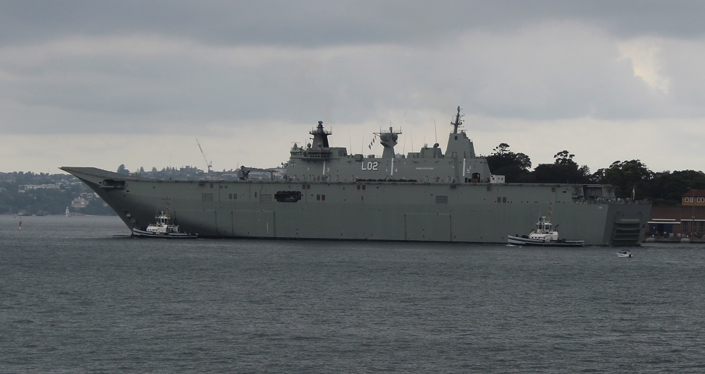
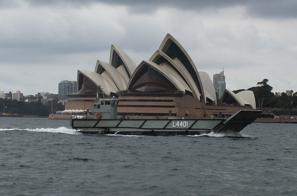
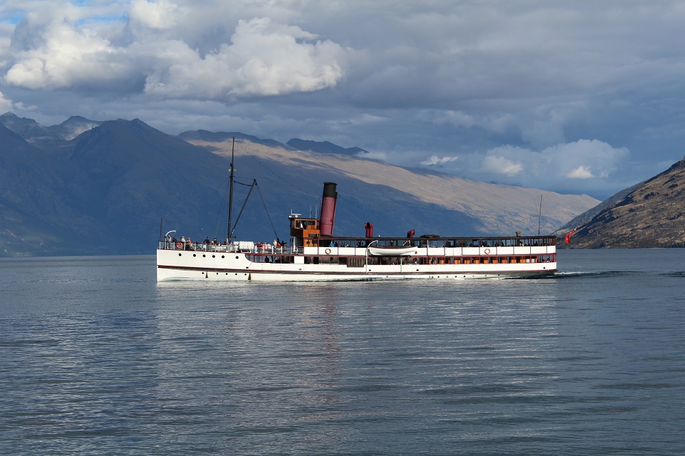
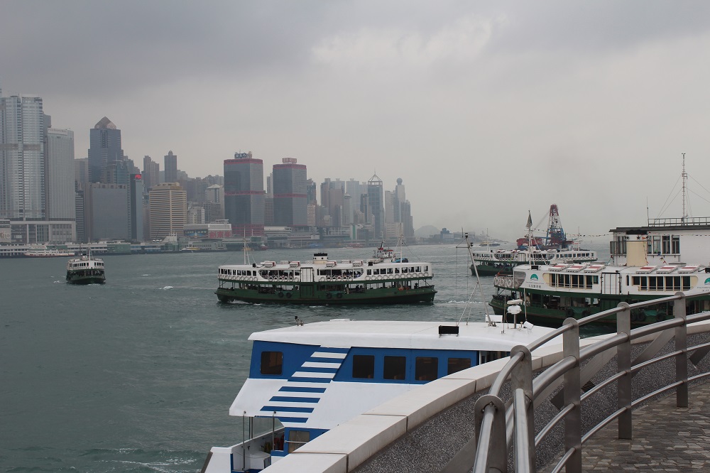
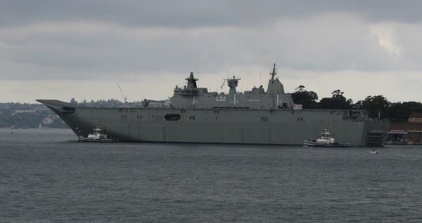
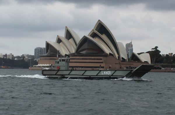
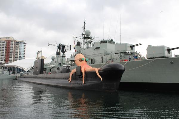
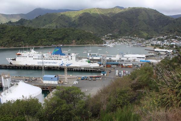
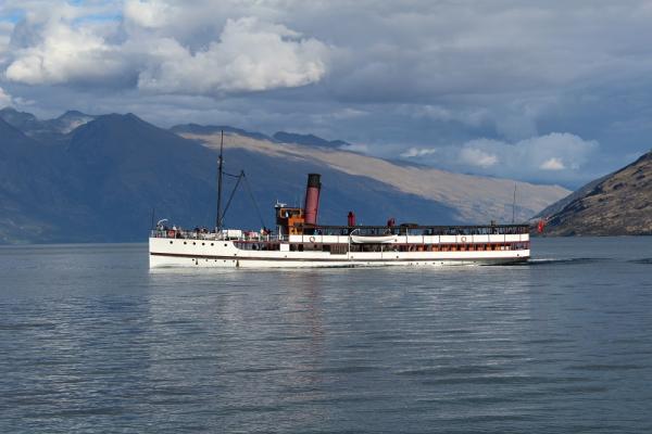
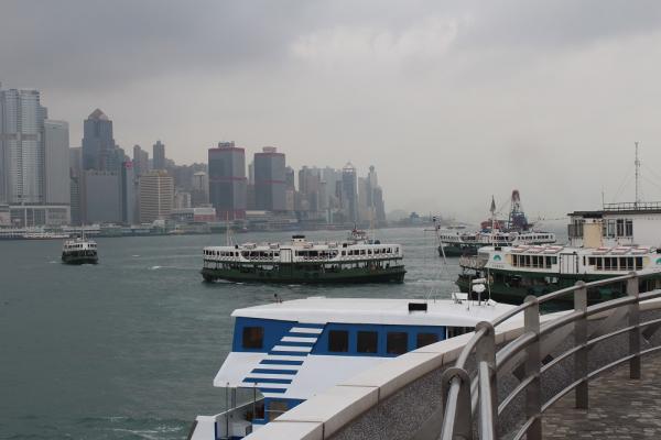
Well I am back in the fold having just had a very pleasant 5 week tour of New Zealand, with time in Australia and Hong Kong. I am a great fan of all things NZ and also of all things Aus (with the exception of Rupert Murdoch) so it was especially nice to find everyone so friendly in such beautiful environments. I even forgive them for beating our rugby team (couldn't care less about cricket). To prove I was there.... In Sydney we saw plenty of cruise liners including this one in a fetching shade of grey.... ....nearby was this vessel which presumably allows its passengers to access the golden beaches...... .....and the submarines have some interesting crew members....... ...the latter is outside of the Aus National Maritime museum which sadly I did not have time to visit. In NZ we travelled from the north island to the south island in this ship, which carries cars, lorries and rail wagons... .....the crossing was rather choppy due to the attentions of cyclone PAM. Not so on the tranquil waters of the lake at Queenstown where the TSS Earnslaw serenely puffed back and forth......... ...but in Hong Kong the waterways are very busy with the Star ferries hooting at each other to get out of the way...... ..... bliss. So....once my brain can work out what day of the week it is and what time, I will start on the second pump mechanism. BTW...I am not ignoring Pomy's question, I am having a PM exchange with him.
-
Pomy, Yes I had problems in this area as well. I am away from my normal web access for the next few days. I will give a better response then - if that is OK.
-
I glued my remaining sprocket wheel in to the starboard cistern. To secure the chain I (permanently) hooked lengths of wire in to the end links. I also drilled two 4mm holes in the cluster base for the inboard pipes to fit. The outboard pipes will simply sit on the deck surface. The wires were then fed down in to the tubes drawing the ends of the chain with them. To secure the wires I turned up two 2mm diameter bungs from bamboo, then drilled 0.5mm holes through their centres. These were threaded on to the wire from the bottom then pushed in to the bottom of the tubes. The bungs were glued to the tubes leaving the wire free for now. The chain could then be adjusted and pulled taught by the wires then the wires secured by a drop of superglue. The wires could then be trimmed off. This ensures the chain is secure at both ends. The bungs also line the chains up centrally within the tubes. The photo shows this almost completed. The left hand wire is yet to be trimmed. Next was a dry run in the waist area of the ship. The cisterns cleared all the surrounding items such as cannon rigging. Unfortunately I have drilled the two holes in the cluster base too close together. This results in the two cisterns being jammed together. Also the crank handles would be too far away from the uprights to which they should be attached. I will have to ease the two holes outwards by 1mm. When I have rigged out the second pump I will make some rodings in the same way as the cannon caps. I keep looking at the chain and thinking I could have made the links finer. I have been giving more thought to the second mechanism and doing some reading on the subject. One document that I consulted was a thesis by Thomas James Oertling called "The History and Development of Ships' Bilge Pumps, 1500-1840" which can be found here . Thomas Oertling has developed this further and published it in a book "Ships' Bilge Pumps - A History of Their Development, 1500 - 1900" ISBN 978-0-89096-722-5. In his thesis he describes the Burr Pump in Chapter IV page 24, the Common (Elm Tree) Pump Chapter V page 32 and the Chain Pump Chapter VI page 73. On page 77 he quotes Blankley (1750) who describes a cylinder of wood with "Y" shaped sprockets set in its periphery. The chain being made of circular, oval or "S" shaped links. At this time the saucers were made of metal. Earlier they were made of wood and referred to as burrs. On page 78 he quotes the London Magazine (1768) which refers to the new improved Cole/Bentinck design that has a spoked sprocket wheel with "cycle" type chain. This suggests that the spoked sprocket type was introduced during the lifetime of Unicorn and that the original pumps would have been of the old type. Did Unicorn ever have the new type of pump? Who knows. Since Unicorn and Lyme could be regarded as experimental ships then perhaps it is feasible that towards its end Unicorn carried one of each type. So.....I think I will attempt to make one of the old type mechanisms. One fly in the ointment - most of the info I have seen suggests the old type mechanism simply emptied directly on to the deck, then the water drained across the deck and out of the scuppers.However if I model one pump with and one without a cistern it is going to look odd. Needs more thought. Still that will have to wait - a few pleasant distractions are coming up in the next few weeks - so no modeling and I will have little Web access which will stop my ramblings for now.
-
Onwards with the chain pumps. I made some tubes for the chains to disappear in to. This was a simple turning and end drilling job. The tubes are made from walnut dowling turned down to 4mm outside diameter with a 2mm hole bored through the centre. The top edges were rounded and the bore opened out slightly at the mouth to give a tappered entrance. The tubes were parted off 9mm long. I also produced the bungs to go in to the front of the cisterns. These were again turned up from walnut dowling. I first turned the dowling down to 3mm diameter, then turned the end to 2mm for a length of 1mm. I then parted it off at 1.5mm long. Although only 2 are needed due to my unfailing ability to lose things I made four of them. This also allowed me to choose the better ones to fit. They need 2 off 0.4mm holes drilled in the ends to take a wire staple to represent the handle. To hold the bungs whilst doing this I gripped them in a pin vice. The photo shows the tubes and the first bung in the pin vice. The pin vice was then clamped vertically in the vice on the milling machine to drill the two holes. Short lengths of 0.3mm brass wire were bent up, blackened then glued in to the bungs. The next photo shows the best two. The rim of the bungs crumbled slightly - the walnut I have is not ideal for this work. The sisterns have a pair of 4mm holes drilled in their bottoms to take the tubes plus one 2mm hole in the leading side to take a bung. This was nerve wracking work - it was like drilling egg shells.

-
Hi folks, Thank you for your words of encouragement and likes. All of you who have commented are modelers that I look up to on this forum. Nenad, I hope I don't make you too breathless - I don't want you to stop breathing! Grant, I am glad you enjoyed my ramblings - I hope you were not sent off to sleep by them. JP, the lids are removable so that the detail can be seen. However I am wondering how practical it will be to remove/replace the lids when the rigging is in place. Well in my old model railway club I had the reputation of making details like working locomotive inside valve gear that was impossible to see once the boiler is fitted - so I am just continuing with my old lunacy! John, thanks for looking in. I am looking forward to more developments on your Unicorn. Piet, my metal work is put in the shade by that on your 0 19. BE, as you say searching for "pinged" items always results in finding previously lost items. In this case it was bits for the quarter deck rail that I made some time ago. I love your replacement figures on your Pegasus. Before you did them the originals looked good but the new ones are a huge improvement. Mike, I am expecting that you will improve on my chain pump efforts. Something to look forward to. ZyXuz, good to hear from you again. Your Unicorn has come on in leaps and bounds. Not sure why the hull has started cracking. Perhaps someone with more experience then me could offer a view. I am sure you will sort it.