HOLIDAY DONATION DRIVE - SUPPORT MSW - DO YOUR PART TO KEEP THIS GREAT FORUM GOING! (Only 53 donations so far out of 49,000 members - C'mon guys!)
×


ianmajor
-
Posts
784 -
Joined
-
Last visited
Content Type
Profiles
Forums
Gallery
Events
Everything posted by ianmajor
-
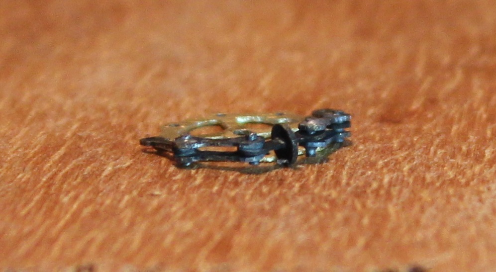
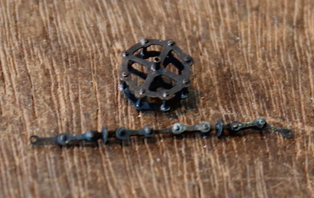
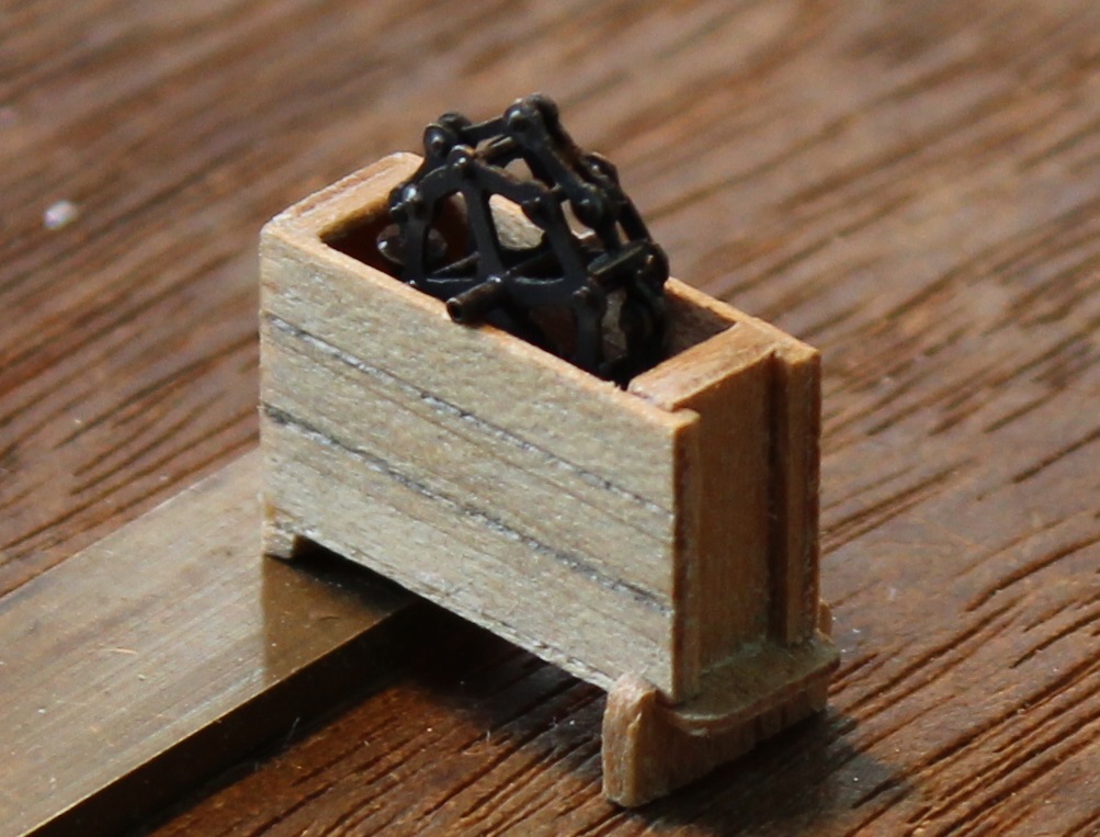
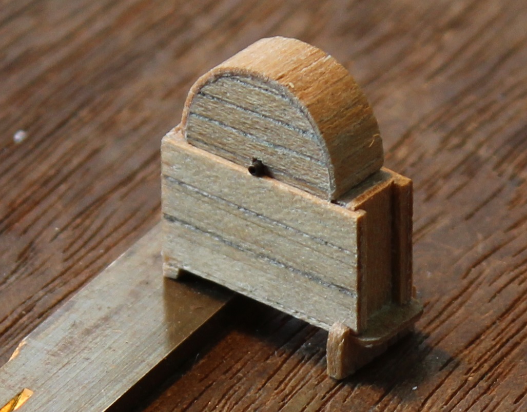
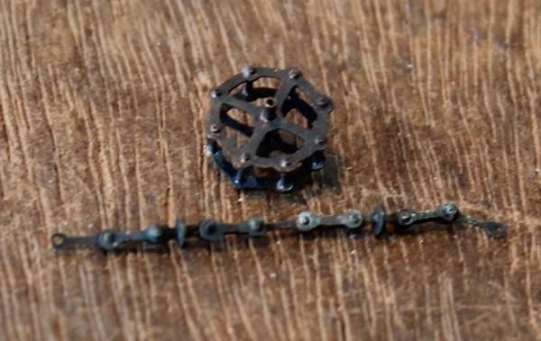
 Then it was time to assemble the chain. The double links were soldered to the cross pins, the single links were left free. To stop the links getting soldered up solid I used cigarette paper between the parts of the link with the paper lightly oiled. Cigarette paper is very useful stuff in the workshop. It comes in various surprising accurate thickness. I use it as above plus I use it to set the right backlash in the gears of my locos - however I don't "roll my own" since I don't smoke. Having completed a length of chain I assembled a sprocket wheel...... Then tried them for fit in one of the cisterns. I hadn't got the chain sat down properly when I took the photo. The chain is a little bit fat. Then I made sure the lid still fitted with the sprocket and chain in place. It did! The cistern now requires a couple of tubes and a bung fitted. I am wandering off again for a while (I will have no tools or Web access) so they may have to wait for my return. Now for the proof, if proof be needed, that Ian's brain is definitely going soft with the onset of old age. The sprocket wheel in the photos above was the second one that I made. The first was nearly complete so I decided to give it a good burnish with the glass scratch brush. To hold the wheel I used a large, sprung, wooden clothes peg. Now I managed to select one that didn't close squarely. So as I was burnishing away the peg sheered. It was instantly converted from a clamp to a catapult and promptly fired the wheel across the workshop. It searched high and low but the wheel was gone. I think there is another lesson there. This means that although I had prepared components for two pump mechanisms I had lost the sprocket wheel for one of them. So I decided there were three options:- 1) Simply fix the lid on the second pump and only have one with a mechanism (simplest). 2) Make fresh components for the second wheel. 3) At the time the real ship was built the pump mechanisms were changing. Earlier mechanisms had a sprocket wheel in the form of a wooden cylinder with 8 off "Y" shaped pieces of metal set in to the circumference of the wood. The chain consisted of small oval or twisted figure of 8 links. Along the chain were either cups or latterly saucers as with the mechanism I have produced. If I make one of these I could have one of each type of mechanism. I will have to give it some thought. Anybody got any views on this?
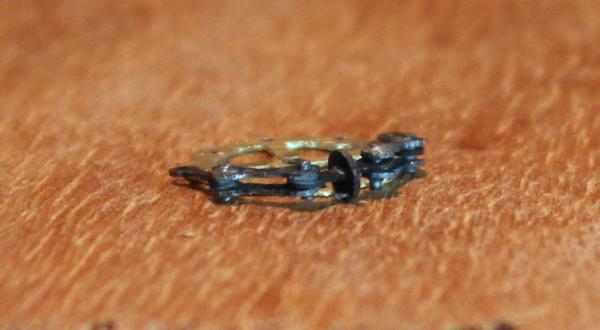


-
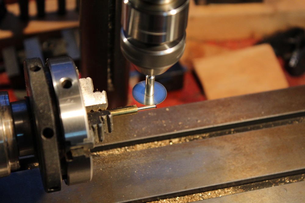
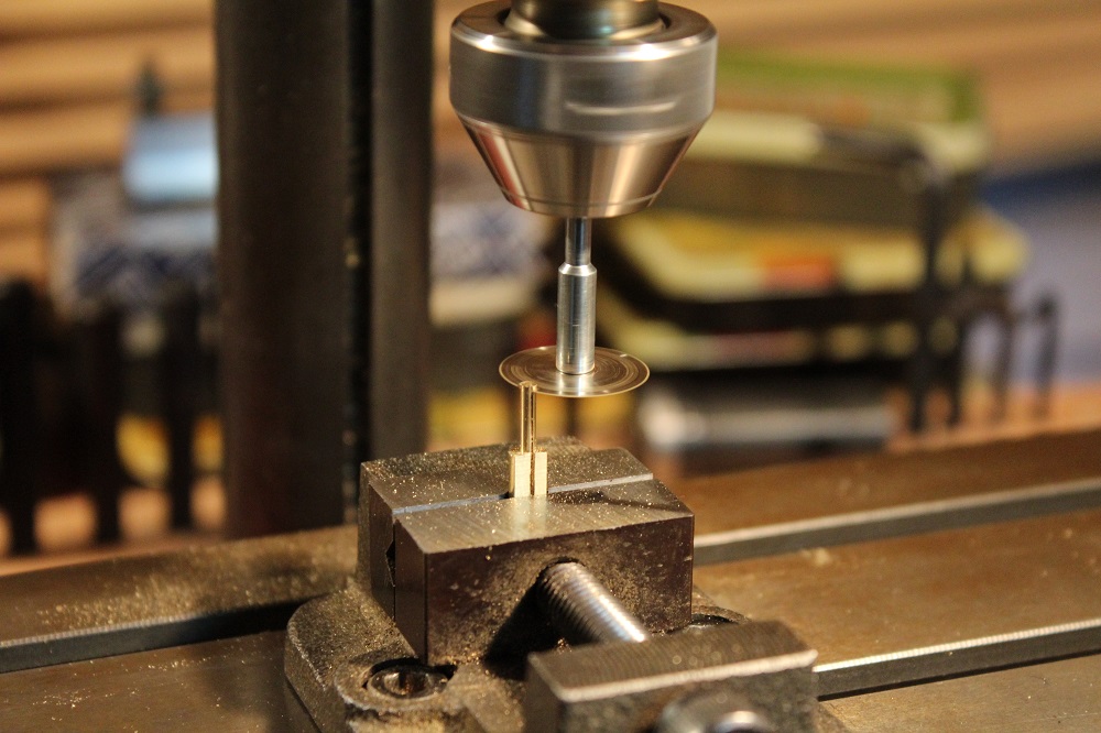
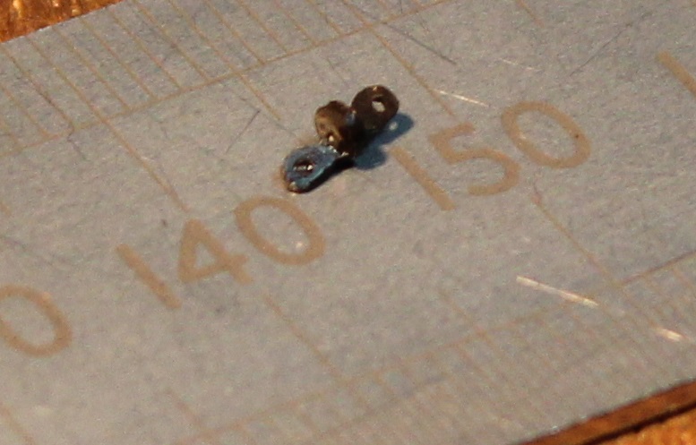
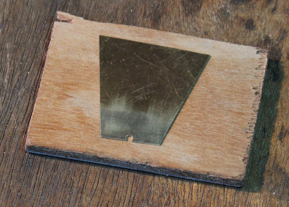
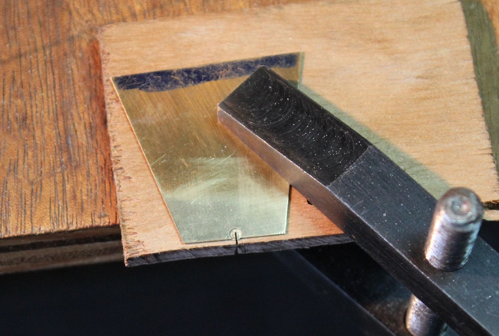
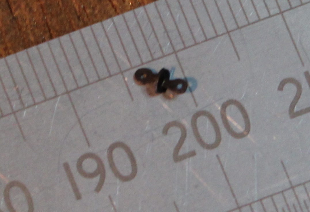
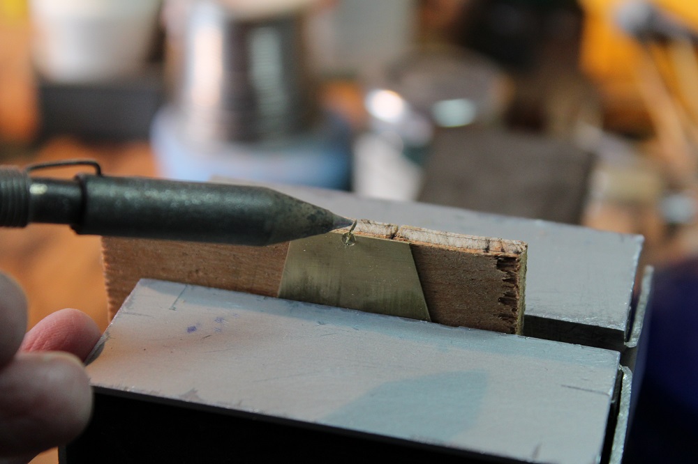
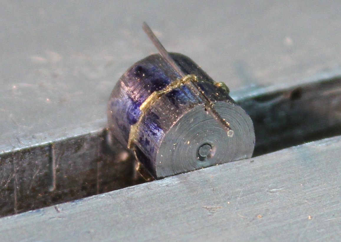
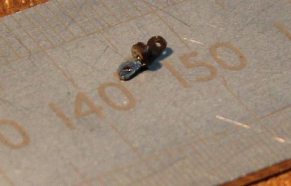
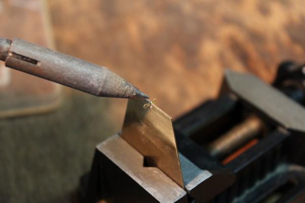
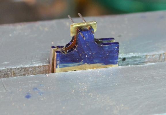
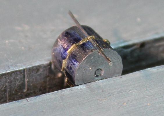
The pump chain is like a cycle chain with alternate single and double links. The difference is that some of the single links have a disk fitted which lifts the water. I have been trying to decide how far apart they were. The diagram shown <here> has the disks every 6th link. Dan Vadas indicates a "saucer" every 4th link - see <here> but as he says only one need to be fitted since the adjacent ones will be in their tubes if the saucer is top dead centre. I decided to go with every fourth link. To make the saucers I turned some brass rod down to 2mm diameter. Then transfering the chuck and rod to the milling machine I used my thinnest slitting disc to cut the horizontal slot along the rod. Then mounting the rod vertically in the vice I used the same slitting disc to cut off thin slices. The result was less than pleasing. The slitting disc is thin steel and tended to wander producing curved cuts. This effect can just be made out in the previous photo where the slot in the rod runs out to the right as it moved downwards. A soldered one of these saucers on to a link and it was all lopsided. I will be using this slitting disc later but will make some backing plates for it to stop it flexing. Back to the drawing board. I turned a fresh length of rod to 2mm and simply sliced off some 0.2 mm blanks. These were then cut almost right across their diameter using a piercing saw. To hold the blanks whilst sawing I drilled a 1.8mm hole near the edge of a thin piece of scrap brass. The hole was then carefully reamed out until the blanks made a good interference fit in it. Then I filed the edge until the hole just broke through. The piece of scrap (with the blank fitted) could then be clamped on to a thin piece of plywood on to the edge of the bench then used like a pin to enable the saw cut to be made. The bit of plywood stops the blank being pushed down (on the cutting stroke) and out of the jig. The whole assemble could then be mounted vertically in the vice to use as a soldering jig, simply add a link in to the slot. Soldering with the wooden backing in place...... ....soldering without. The result was a much better saucer/link.


-
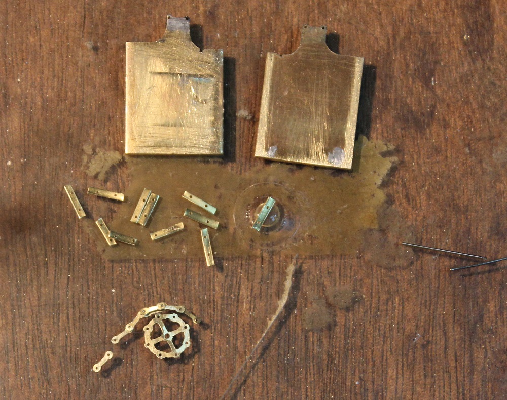
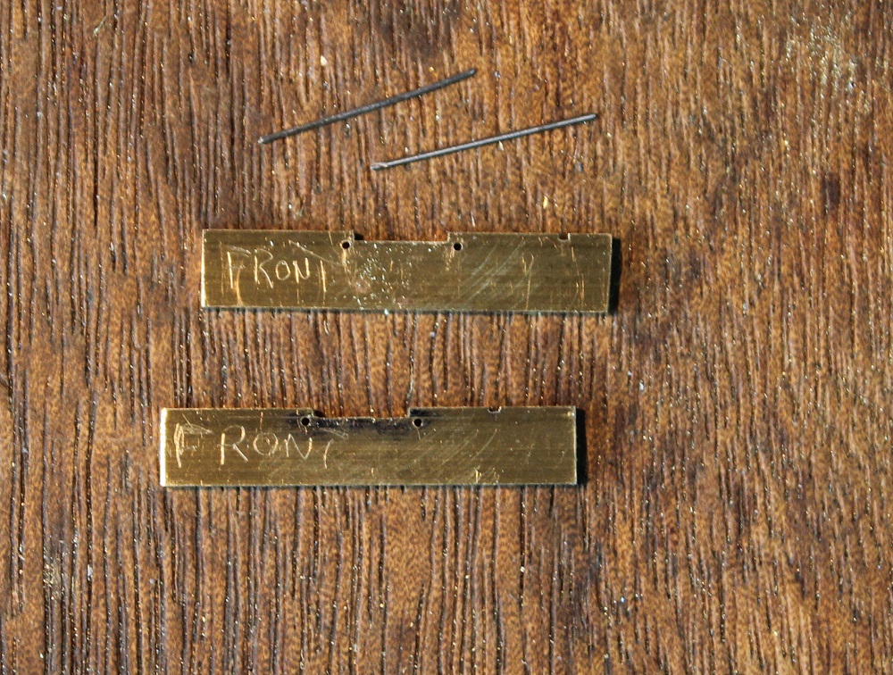
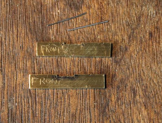
Next is to make the components for the chain. The challenge is both in holding small parts when filing and to get them (as far as possible) identical in size and shape. I feel another jig coming on. The chain links go around an arc that has a radius about 0.7mm greater than the wheel. I calculated the linear distance between adjacent holes on the chain to be 3.44mm. The jig has two identical parts. Parallel to one edge are two holes 3.5mm apart. Between the holes the area is milled down to a line tangential with the top edges of the holes. The area around the holes is shaped as a curve with the two ends running straight down. Blanks were cut from 0.2mm brass with holes at 3.5mm apart. These were then clamped in batches between the two parts of the jig with a spacer at the lower part of the jig to keep things square. The blanks are then filed down to the shape of the jig - they are then rotated through 180 degrees with the filed edge downwards so that the opposite edges could be filed. The next picture shows a batch of blanks loaded in the jig ready for filing. The next picture shows the two halves of the jig, some blanks awaiting filing, and a set of completed chain links around a wheel. The wheel looks like it needs a little more work. Nothing like photographs to show up weaknesses.

-
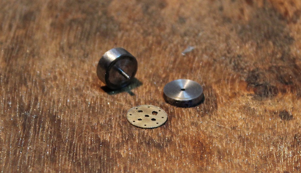
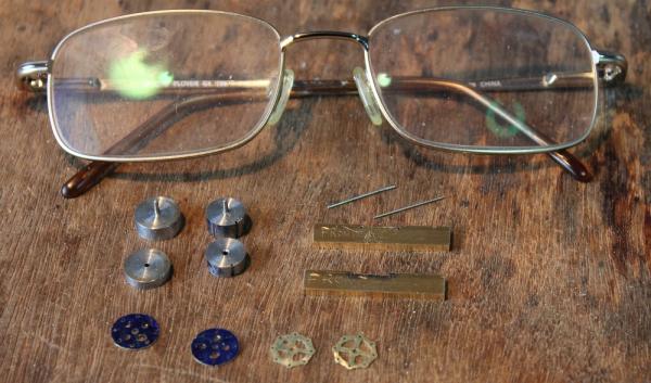
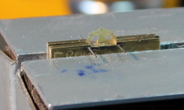
Next up was shapeing the sprocket wheels. For this I made some filing jigs. The photo shews the jigs along with sprocket wheels at various stages. The first up was a straightforward button. This consisted of 2 cylinders each 10mm in diameter which I turned up on the lathe. One part has a 1mm hole drilled through the centre the other has a 1mm stub. To use it the part to be filed is trapped between the buttons then filed down to match the buttons. The first stage produced discs large enough to cover the bosses around the periphery of the wheels. The second pair of buttons were 8.5 mm in diameter. These I used to produce the curves between the bosses. With the buttons in place the ring of holes was just obscured making it difficult to keep track of where the bosses should be. To overcome this I cut a slot across the two buttons to allow a piece of rod to pass through one of the holes. It was then a simple matter to file around. The next photo shows this in place. Next up was a jig to enable the spokes to be filed. This consisted of two identical parts. Each had two holes 8mm apart ie the distance between two opposite holes on the wheel. Between the holes the edge was milled down to form the filing edge for the spoke. The next photo shows the jig in use. The left side of the wheel has been filed down to the spoke - the right side has yet to be started (other than a pilot hole). Care has to be taken to avoid filing in to the centre hole. The part is then rotated through 90 degrees and filed again. All 4 spokes have one edge filed at this point. The part is rotated 90 degrees again and the part filed. This shapes the opposite edges of the first two spokes. Finally this is repeated leaving all 4 spokes dealt with. This technique works for any even number of spokes - as long as you can get the files in between them!

-
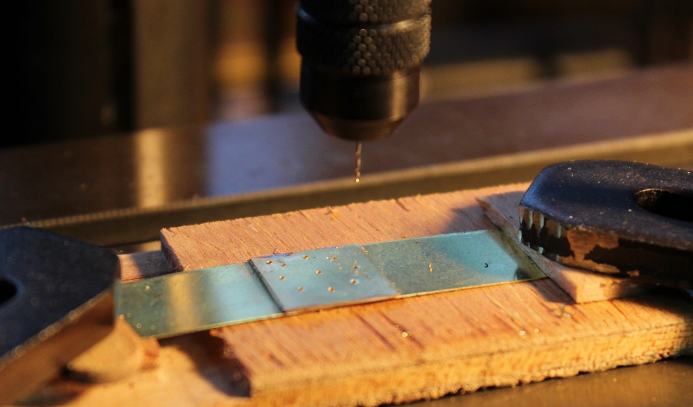
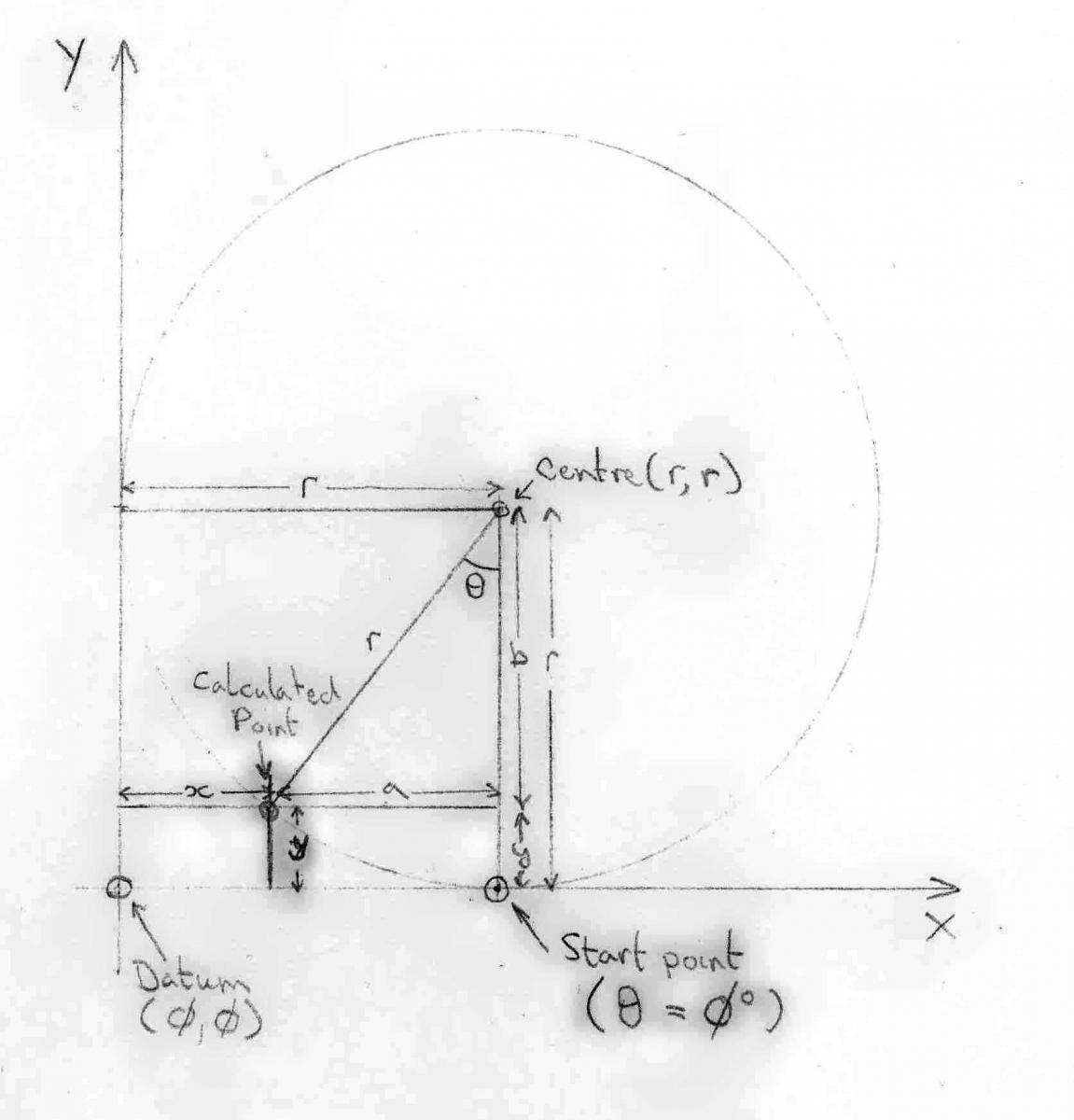
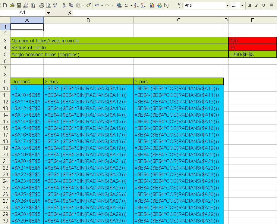
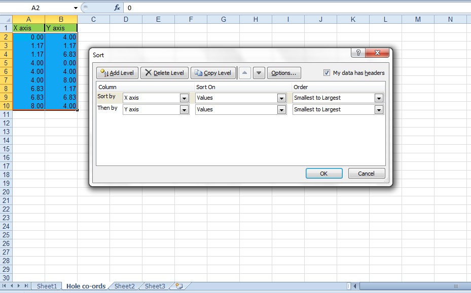
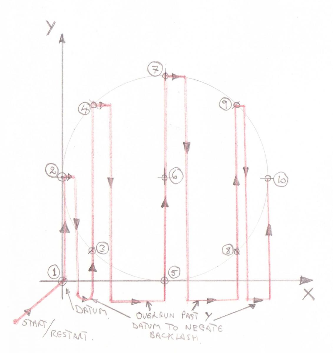
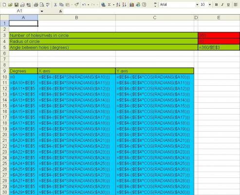
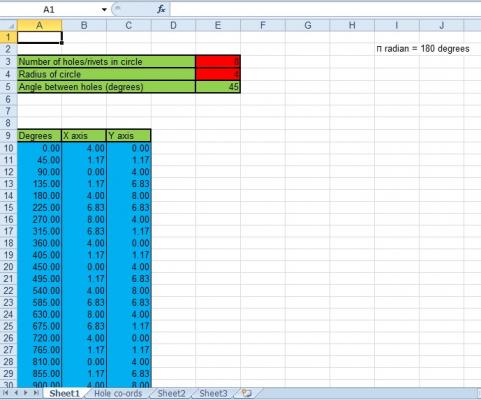
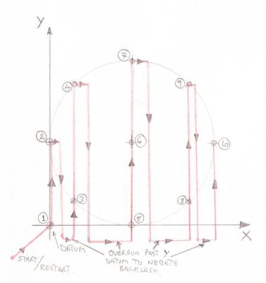
Thanks guys for the likes and wonderful comments. Time to start on the pump mechanisms..... The first components for the chain pump mechanisms were the sprocket wheel sides. I got my info from a variety of sources including the diagram <here> and <here>.... and <here>. Each wheel side has 8 off 0.5mm holes in a circle with a PCD of 8mm.(PCD is the Pitch Circle Diameter being the diameter of the circle that passes through the centre of each of the holes). A 1mm hole is also required in the centre for the shaft. I tack soldered four blanks of 0.2mm thick brass together and drilled them using the X/Y co-ordinate wheels to locate the holes. You will note there is a hole that I drilled in the corner that is outside of the circle. This is the my datum point (0,0). I used this if I "lost" my place, just winding the co-ordinates back to 0,0 then winding back out to where I should have been. To work out the X/Y co-ordinates of the holes I created an EXEL spreadsheet with formulae. I use the Scrooge's version of EXEL which is very limited. It doesn't support macros so I can't use Danny's rigging and masting spreadsheet which is full of them. You may be interested in my process. If not skip to the next entry..... Starting with some geometry...... In the diagram the datum point is at X/Y co-ordinates (0,0). The circle of radius r around which the holes will lie touches both the X axis and Y axis tangentially so its centre lies at co-ordinates (r,r). The first hole I arbitrarily set where the circle touches the X axis (r,0). The remaining holes are located using the incrementing angle ϐ. The increments to this angle depend on the number of holes, in my case there are eight holes giving increments of 45 degrees (360 divided by 8). To calculate the X coord (x) and Y coord (y) of each hole: Note the right angle triangle with sides a, b and r with angle ϐ opposite a. a = r * sin(ϐ) b = r * cos(ϐ) ...and.... x = r - a y = r - b ...replacing... x = r - (r * sin(ϐ)) y = r - (r * cos(ϐ)) In my case r = 4mm and ϐ has incremental values 0, 45, 90, 135, 180, 225, 270, 315. In the last two equations remove the "x" and "y" characters which leaves the "=" as the first character (gives a function). These can now be used as basis for the formulae in the spreadsheet. The next picture is a screen grab of my spreadsheet with EXEL in formula evaluation mode so that the formulae are displayed rather than their calculated values. The red cells are for input information. Cell E3 is where you type in the number of holes required (I have set a default of 360). Cell E4 is where you type in the radius of the circle (default of 10). The next cell down (E5) is the first formula (=360/$E$3) which will display the result of taking the fixed value of 360 divided by the content of cell E3 (number of holes required) giving the angle between each pair of holes. The "$" signs make sure that we always point to column E, and always point to row 3. Cell A10 is our first value for ϐ ie set to 0. The remainder of the cells in this column add the content of the cell above (previous increment of ϐ) to the content of cell E5 (angle between pairs of holes). For example cell A16 contains =$A15+$E$5. Columns B and C contain formulae derived from our geometry work above. Example in column B, cell B2 relates to "x = r - (r*sin(ϐ))" so contains: =$E$4-($E$4*SIN(RADIANS($A10))) $E$4 is the cell containing the radius. $A10 contains the value of ϐ. Note the cell ID has no $ in front of the 10 (row number), so the formula in the next cell down will have $A11 ie pointing to the incremental angle generated in this row. EXEL works in Radians but my angles are in degrees. There is a built in EXEL function (RADIANS) that converts degrees to radians. This is used in the above function. Column C formulae only differ in using COS rather than SIN. For the main table you only need to manually type in the formulae in rows 10 and 11. To generate the remainder select cells A11, B11 and C11, copy them then paste in the cells below. EXEL will automatically increment the row values that are not prefixed with a "$". (More quickly, select the three cells. Note in the bottom right hand corner of the rightmost selected cell is a tiny black square, position the curser over it (the curser will change to a thin black cross) press and hold down the select button then drag the square down as far as you want to copy, then let go of the select button. The copy will take place. The next picture shows the same EXEL sheet in normal display mode. I have selected the number of holes as 8 and the radius of 4 (mm, inches, 1/64ths whatever). It has worked out the angle twixt the holes (45) and calculated the X/Y co-ordinates for the different angles. In this case I only need rows 10 to 17 but to cater for any number of holes the formulae go way beyond this going round and round...... To make this info usable, I copied the appropriate X/Y co-ordinate cells, including headings, copied the cells then on a new sheet did a paste special/values which strips out the formulae and leaves the calculated values. (In my case I copied columns B and C between rows 9 and 17). I added an extra pair of entries on the end with the radius in each to mark the centre. (In my case (4,4) ) Then selecting all of the cells on the new sheet I did a sort - "sort by" X axis followed by "then by" Y axis as shown on the next picture. This gives the X values in ascending order, and the Y values in ascending order within each X setting. (see for X value of 4, Y has 0, 4 and 8) . Drilling the holes in this order ensures the the X co-ordinate wheel is always progress in the same direction. Shuttling back and forth will cause large errors due to the backlash in the leadscrew. The Y co-ordinate can be worked in one direction for each X setting. When moving on to the next X setting, The Y co-ordinate needs to be wound back beyond the datum value then wound forward again to take the backlash out. The diagram shows the order I drilled the holes along with the direction the drill took. Well enough of this.......


-
Hi Piet, Rough sketches eh?! I must see your finalized diagrams - they must be a combination of technical drawings and works of art.
-
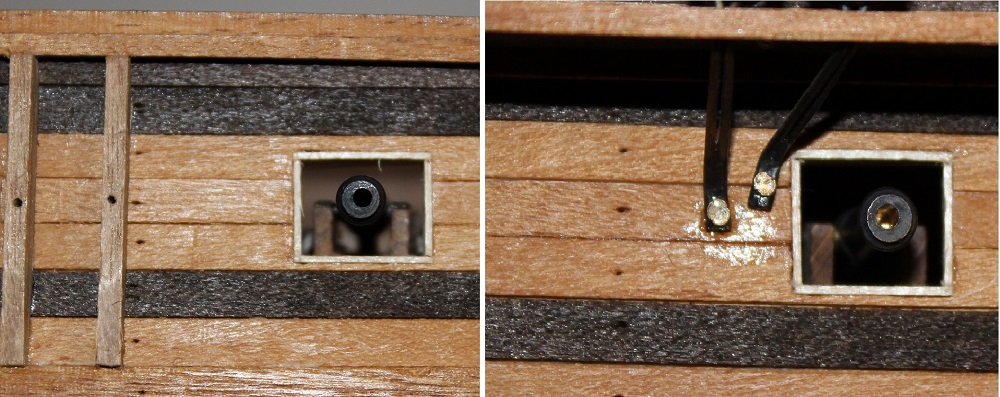
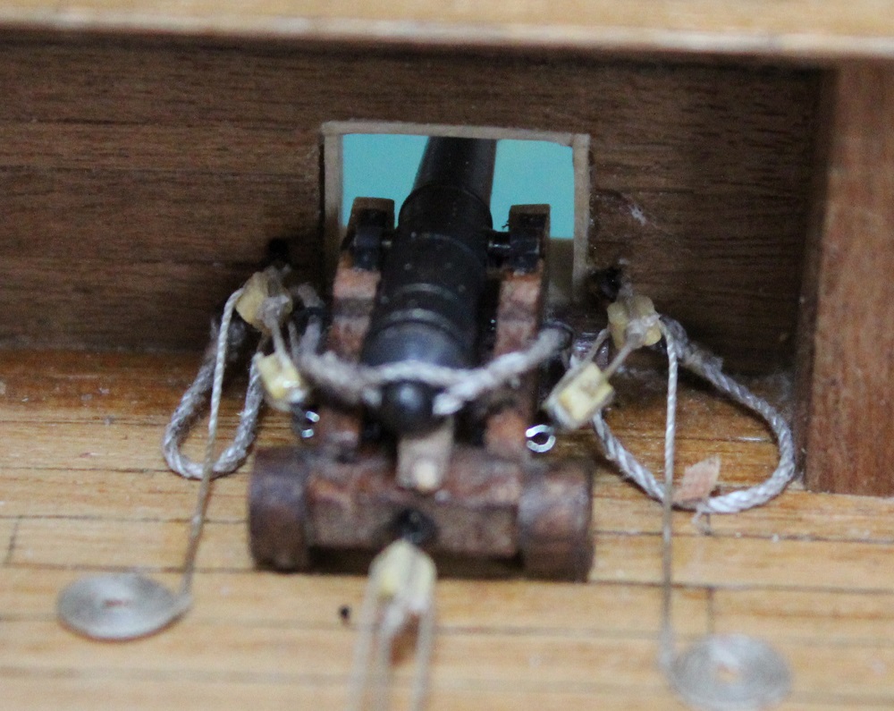
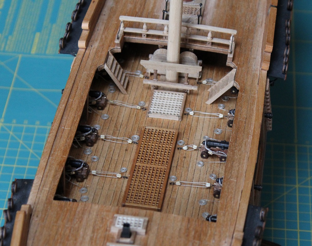
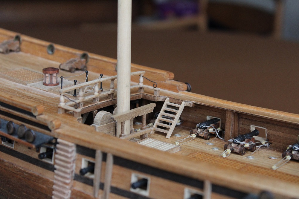
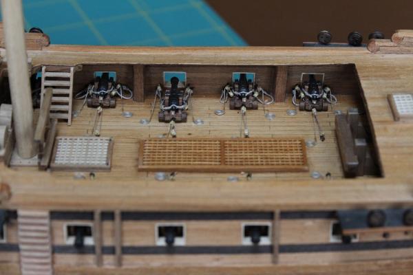
Initially I was concerned about how the lack of rigging on the remaining cannon would compare. In the event it is hard to see that there is any rigging in place when viewed through the ports. The non rigged cannon are also in deep shade under the decks. To illustrate this, in the next picture the left hand cannon is fully rigged, the right hand cannon has no rigging. It also shows that if you get air trapped in the cannon bore when blackening it the bore remains bright. Doh! Plus what lovely off centre bores the Corel cannon have. A couple of errors/problems encountered. The first was that when I pre drilled all the holes in the bulwarks for the side tackle I had the holes about 1mm too low. The result was the side tackle blocks closest to the bulwarks try to occupy the same space as the front trucks hence the side tackles don't sit neatly as shown in the next picture. Note how the far blocks are pushed out sideways through approx 90 degrees. These blocks are fairly well obscured so I can live with this but I must make sure I get this correct on the cannon on the quarter deck where the tackle is in full view. Another issue was that the deck planking was varnished long ago (it was in theory finished 30 years ago). This meant that it was a struggle to get the ropes to stick down and stay down using super glue. So after several attempts more glue was used than desirable. In places I will try to remove some of it with Isopropal Alcohol. Next is to finish the pumps. Then I can climb back out of the waist area.....at last.


-
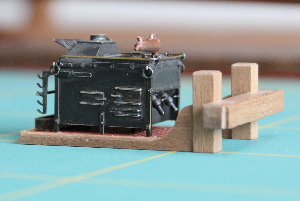
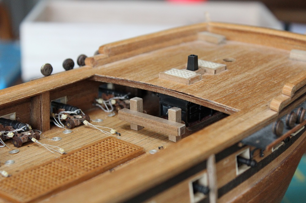
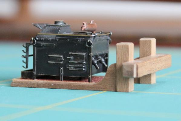
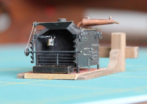
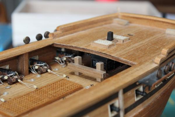
I turned my attention to the stove. Due to the restricted headroom it was difficult to fit it under the fore deck. So as part of final assembly I reduced the lengths of the legs such there was only 2mm clearance between the stove bottom and the brick base. I also reduced the height of the fittings on the still. A down side was that the stove now sits low against the drip try by about 0.5mm. It is not immediately obvious so I will leave it as is. The stove now slid under the fore deck easily. To fix it in place I put super glue on the underside of the base. To avoid getting glue on the adjacent grating as the stove slide in I laid in a strip of polythene which I was able to pull clear once the stove was in the correct position. The flue was glued in place through the fore deck. I also added the deck beam under the rear edge of the fore deck. Of course the deck supports the beam rather than the other way round. This has got rid of the ripple effect in the deck. As can be seen in the next photo the beam protrudes beyond the deck in places so needs some final dressing. Sadly with the beam in place the still is now completely invisible.
-
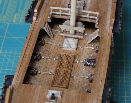
Gosh! Was it really September when I last updated this log? I must be slacking. I have been making progress on the Unicorn - despite the odd distraction - mostly repetitive stuff rigging cannon. I have now finished the 12 cannon on the main gun deck that I intend to do (positions 2 to 7 counting from the bow). I made up some Flemish coils (as I believe they are called) which were added to the cut ends of the cannon rigging. I have seen the debate about how the excess rope should be handled but decided that my cannon were laid out as for an inspection. I also rigged one cannon in the "run in" postion. I have debated this with myself. This looks OK from above but when the ship is viewed from the side it looks like a smile with a missing tooth. I think I will get used to that. The quarter deck rail is now fixed permanently in place. I did a dry assembly of the pump cluster which revealed two coils foul of the pump bodies - it is a bit cramped around there. So the coils were moved. With the pumps and ladders in place the rigging on the cannon in position 7 is fairly well obscured. The lack of rigging in position 8 is not very obvious through this cluster either.

-
Mike, You will have to glue some sandpaper to the palms of your old mittens. Then you will get a nice smooth curve on your hull - though your nose and ears will still freeze and drop off whilst you are doing it.
-
John, That is such a big improvement on the Corel set up. Lovely work. With the raised deck I think it will look great with open rails around the quarter deck.
-
Lory, It is interesting that you restart work on this model at this time since soon, on January 24th, it will be the 50th anniversary of the death of the great man himself!
-
Dafi, Happy New Year to you. It is great that you are introducing the personal aspect of life on ship, particularly in wartime, it completes the the environment in which these sailing ships existed. By the way (to take a very light view) have you seen the film "Carry on Jack"? It introduces a whole new (and very British irreverence) to the battle of Trafalgar.
-
Piet, The model gets better and better. Merry Christmas to you and Gwen and a happy new year (and many more of them).
-
Mike, Love it. This ship is turning out very nicely.
-
Martin The Maun rule I have seen advertised on Amazon and ebay. Not sure of the availability in the US. The blade handle I have seen on UK sites eg https://www.eileensemporium.com/index.php? page=shop.product_details&flypage=eny_fly_default.tpl&product_id=3643&category_id=172&option=com_virtuemart&Itemid=9 I could not find any US sources. If you have any queries on it drop me a PM. Hope this helps.
-
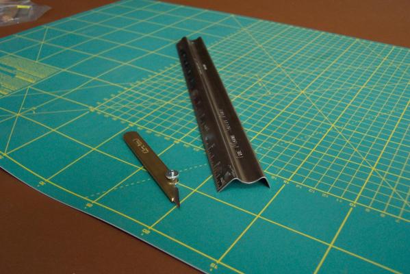
Mike, Like Jason I am envious of the result of your work - though I didn't realize you were getting a good red finish to the wood by staining it with your own blood. I thought you might be interested in an alternative for a cutting edge which we got for my wife to use. It is a Maun Safety Rule. It has an "M" cross section. You place your fingers in the trough up the centre which keeps them well clear of the blades. Mine is 12" long which produces a very stable cutting edge which is not prone to rotating as you cut. It is also very comfortable to use. Here is a photo of it:- Having said that I still use my 12" and 18" straight edges and have never cut my fingers whilst using them. Now that is tempting fate! I always stand whilst cutting so that I am looking and bearing directly down on the work. This reduces any sideways forces that may pull the blade away from the straightedge (damages work) or over the straightedge (damages fingers). This also allows you to keep the knife/scalpel handle vertical which also helps prevent wandering. I have included my Swann Morton knife in the photo. It has a handle that extends along the back edge of the blade almost to the point. This reinforces the blade and reduces the flexing which also reduces wandering. It also reduces the blade's tendency to bend as it enters the piece being cut so improving your chance of producing nice right angled cuts on thicker material. As usual I am probably teaching granny to suck eggs!
-
Mark, Whilst you were singing did you get to play with the pencils on the "Group W" bench? Not to forget - nice work on the ship.
-
Freek that is a great photo. Very atmospheric.
-
Daniel, Fabulous photos. The chap being super critical looked grumpier than me. When I initially saw your last photo I thought that Fritz Lang's Nosferatu had become a member.
-
Piet, The dingy is taking shape and looking good. I look forward to your next builds. I don't have sticking plasters on my fingers to cause problems but I do have rough skin that catches on small detail. My wife's answer was to get me to use her hand cream. Although it hasn't improved my model making it does make me smell nicer!
-
Hello Peter, Just joined your audience. I hope your model doesn't develop the same propensity for catching fire that the real Cutty Sark seems to have!
- 207 replies
-
- 2
-

-
- billing boats
- cutty sark
- (and 1 more)
-
Piet, Absolutely brilliant. Your Father will be smiling down on it I am sure. Do we get the shot of the proud constructor/owner stood behind it?
-
Chris, Excellent tutorial. Thanks.