HOLIDAY DONATION DRIVE - SUPPORT MSW - DO YOUR PART TO KEEP THIS GREAT FORUM GOING! (Only 53 donations so far out of 49,000 members - C'mon guys!)
×


ianmajor
-
Posts
784 -
Joined
-
Last visited
Content Type
Profiles
Forums
Gallery
Events
Everything posted by ianmajor
-
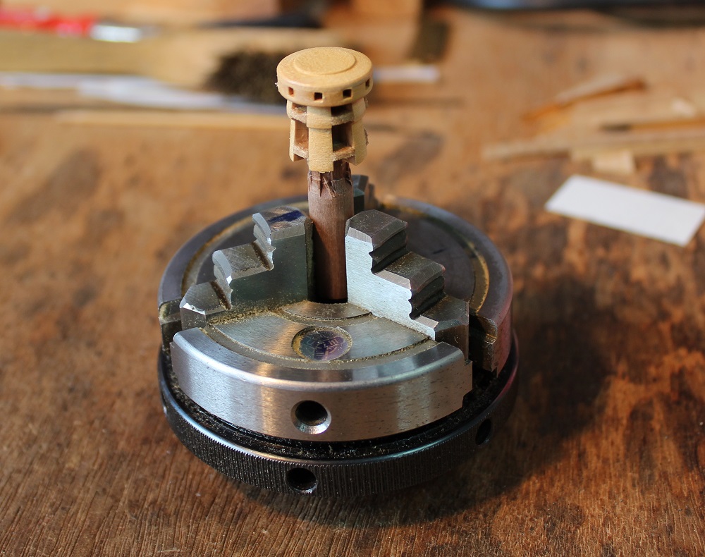
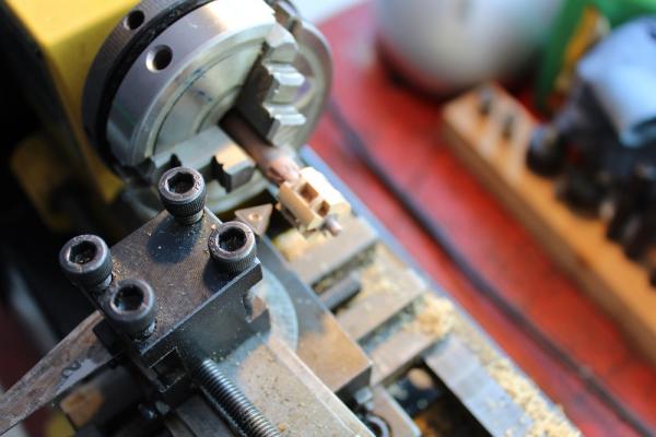
 To assemble wheel and hub I made a sacrificial jig out of some scrap pine. This was turned to about 20mm diameter. It will remain undisturbed in the chuck until the wheel is complete. I transferred the chuck/jig to the dividing head on the milling machine to drill 10 holes around the jig which were highlighted with a pencil. This will indicate where the spokes will go in the rim. For the rim I made 5 felloes which I glued in a ring on the end of the jig. I am fitting 2 spokes per felloe - similar to wooden road wheels. This is differnet to Dan's - he has 10 felloes with each having only one spoke. Turning the outside of the rim was straightforward. For the inside I used a small boring tool - I had modified one of these for another job and it just squeezed in. At this point I diverge from Dan's approach. He assembles and machines all the components on the surface of the jig. Then with careful use of solvent he detaches the completed wheel from the jig. Now his skills far outstrip mine and I could see my wheel ending up as a pile of bits as a result! My solution was to turn the completed wheel off the jig. However to keep the wheel under control whilst doing this I extend the hub deep in to the jig. My first move was to end drill a 5mm hole deep in to the jig. The chuck containing the jig was moved to the tailstock. A piece of square section boxwood was held in the 4 jaw chuck and turned down to 5mm diameter. Glue was applied to it and the tailstock used to push this dowel squarely in to the jig. The pencil marks show how far in the dowel has gone.
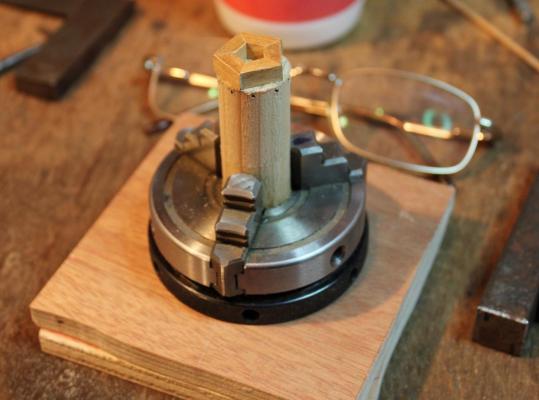


-
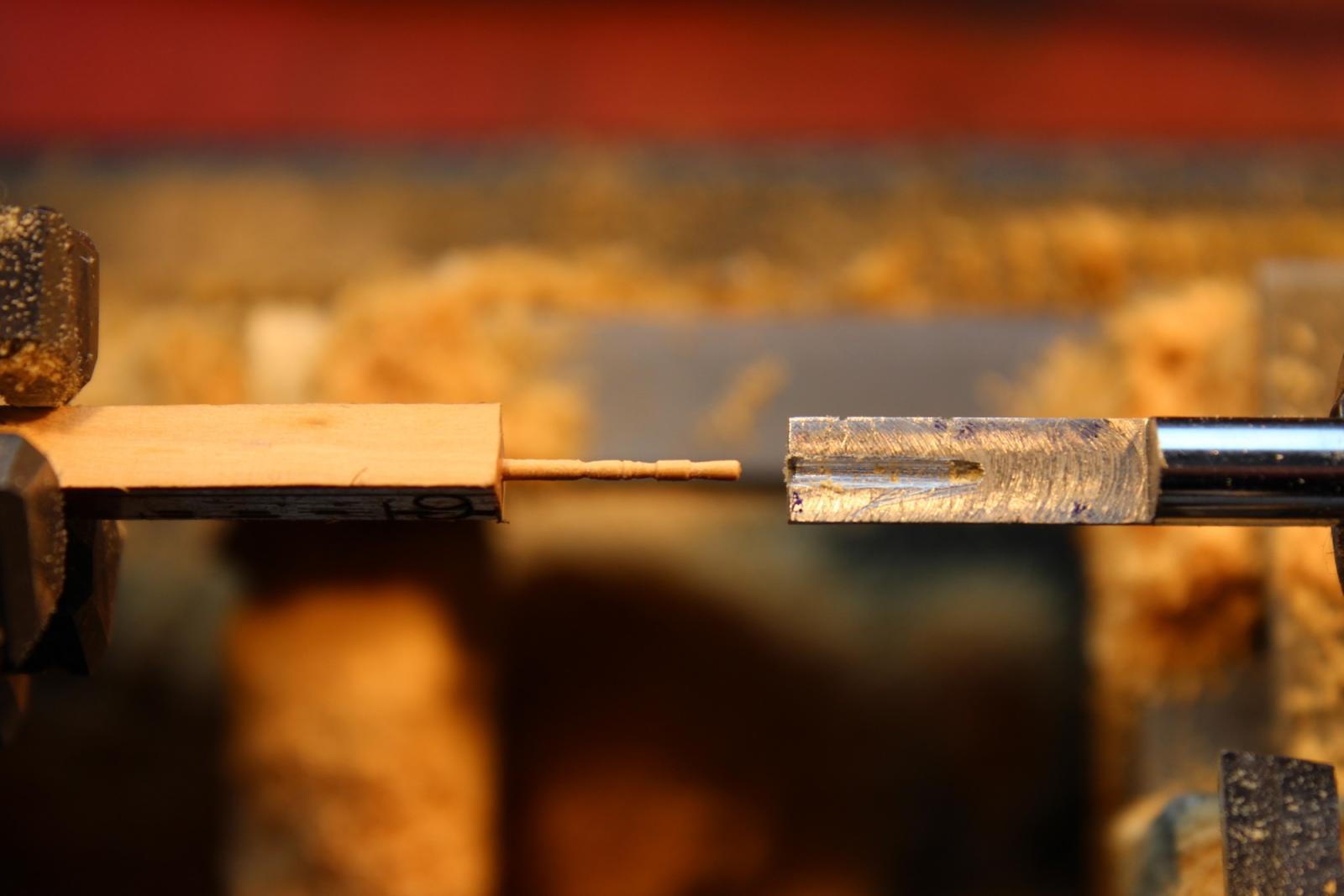
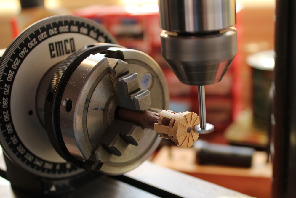
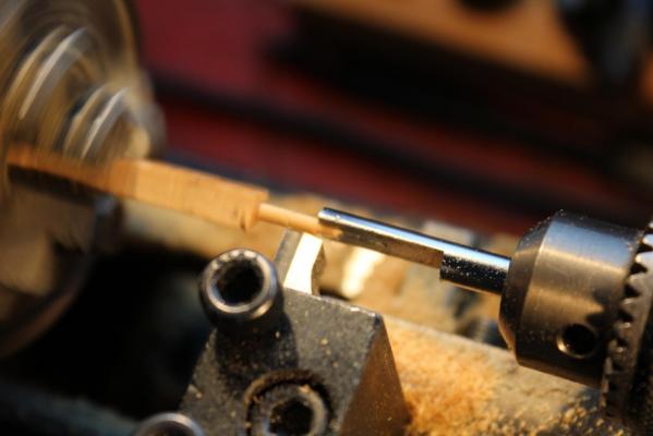
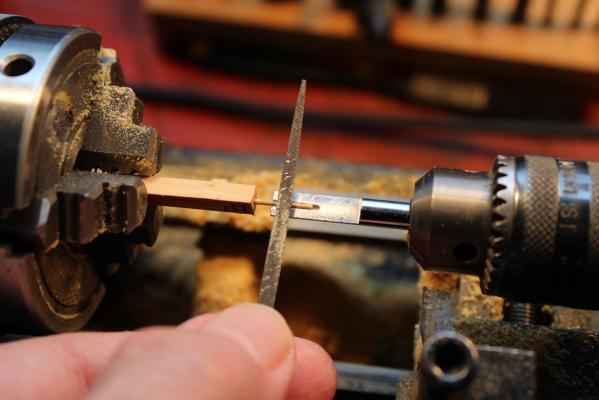
Hum, I notice again that it is more than two months since I last updated my ramblings. As (Landlubber)Mike put it in his log "life just got in the way of things". I had an unexpected week in hospital and will have more visits in the new year when the medics expect to remove a bit or two of me. I think I am starting to emulate the Cheshire Cat in Alice's Adventures in Wonderland by "slowly disappearing until all that was left was his grin". Sadly a disembodied grin would not be much use as a model maker! Anyway enough of this rubbish.... I had decided the belfry that I had made was too small so I have generated dimensions for a larger version. I was in the middle of milling the new belfry cap when I was so rudely interupted. Returning to it a few weeks later was not satisfactory so I abandoned it for now. As a change I decided to produce a replacement ship's wheel. The Corel wheel looks like it would be more at home in a modern cabin cruiser than on a 18th C ship. It has 8 spokes - I decided on one with 10. I based my efforts on Dan Vadas' version in his Vulture log (here) though since mine is approximately half the size of Dan's I went for a slightly different approach. Bye the bye, as I approached the end of making this wheel I also noticed that wheel production is flavour of the month on MSW. Some excellent examples are in EdT's Young America log (scale 1:72) (here) and Alexandru's (guraus) Victory log (scale 1:48) (here) . The latter is a double wheel. The above aproaches are different to each other and to mine! The first things I produced were the spokes from some square section box wood. To stop the wood flexing away from the tool I produced a simple back rest from 6mm steel rod. This was end drilled deeply with a 1.1mm bit. It was then filed or milled to half its width to expose the hole and debured with a small round file. The back stop was mounted in the tail stock with its flat surface vertical. The end 2mm of the work piece was turned down to 1.1mm which was then supported. The work piece was turned down to 1.1mm for 12mm and the backstop advanced to support this. The piece could then be turned down to 1mm diameter. To detail the spoke I rotated the backstop so that the flat surface was now horizontal. Detailing was done with a small triangular file. The photo shows holding the file in place. The chuck is not rotating because I have my hand forward of the work for photographic purposes. I actually approach from over the tail stock to keep my hand well away from the spinning chuck. The next photo shows the spoke ready for sawing off. There are some marks on the backstop that I made to act as a guide for detailing. I made more spokes than are needed to allow selection of the best ones.

-
Hello Shipcarpenter, You have produced a beautiful model. Congratulations on its completion.
- 79 replies
-
- 2
-

-
- santa maria
- amati
- (and 2 more)
-
Mike, That is coming along very nicely - you are going to have a very attractive model there. Like you I have found life getting in the way of modelling - but hey ho should make progress soon!
-
Piet, Have been away for a while so am catching up with your log. Glad to see that you continue to create great work. Like Carl I am struggling to see the pintle pin.
-
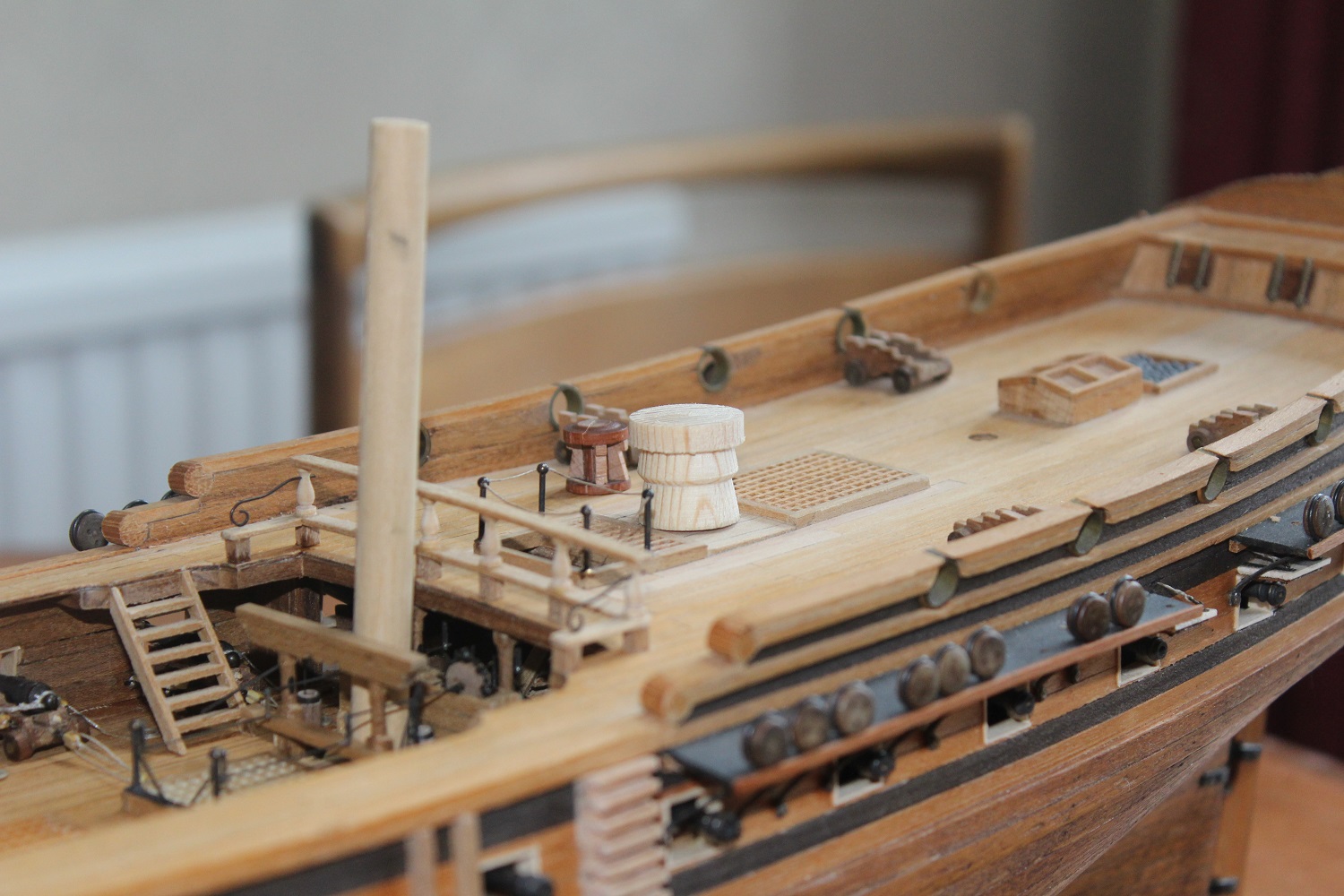
Thanks John. I had much enjoyable time with the grandchildren. This included a ride on a boat through the Anderton lift in Cheshire which raises narrow boats from the river Weaver up to the Trent and Mersey canal. I am pleased that I used boxwood for the capstan. It is a lovely wood to work with and produces nice attractive results. It is a pity I don't have much more - and probably won't get more.
-
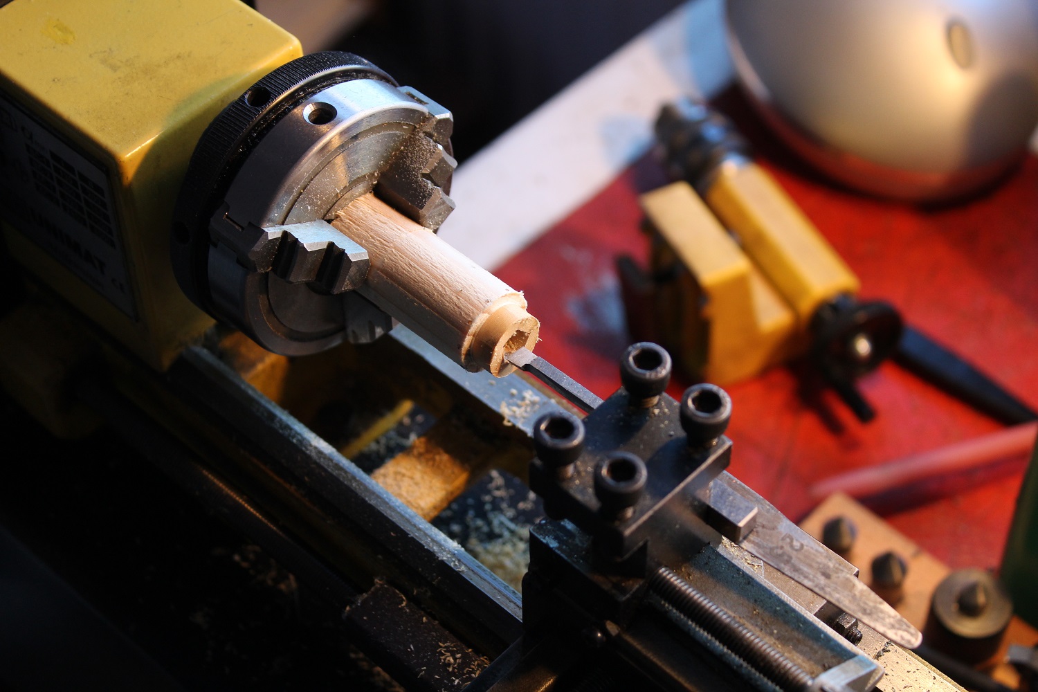
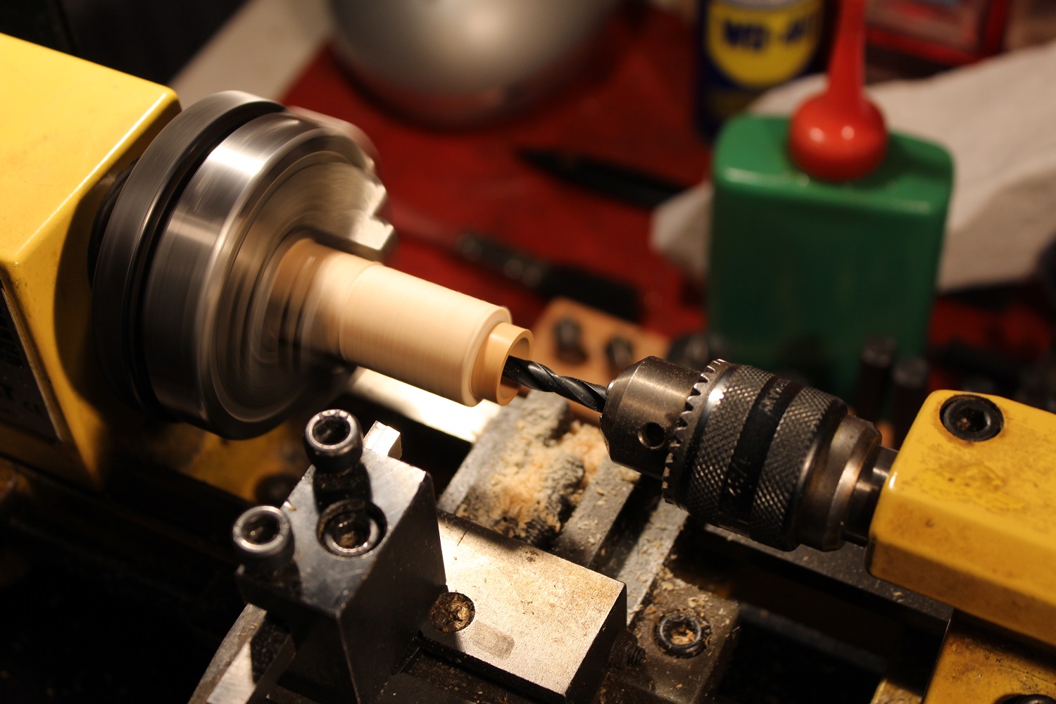
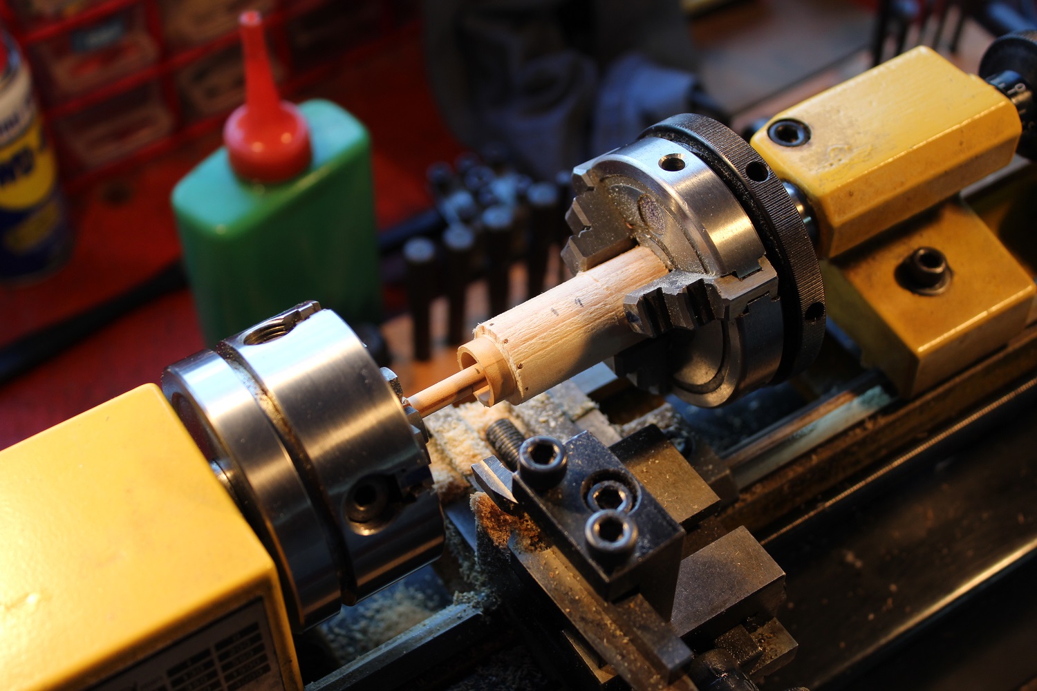
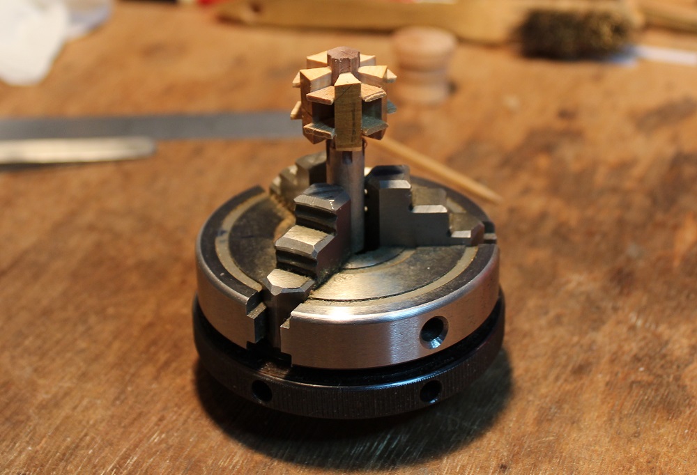
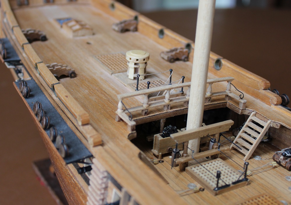
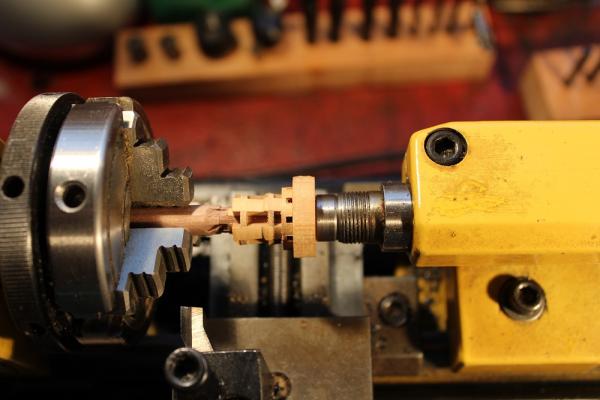
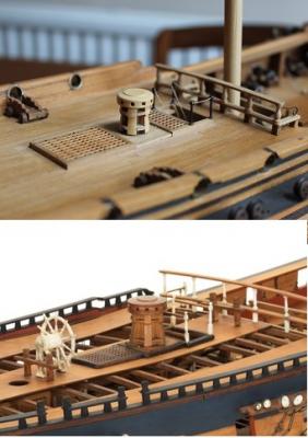
The chuck with the wooden barrel then had its turn on the mill being attacked by the new cutter. This produced some nice clean slots. The whelp blanks were cut slightly over lenth and were the glued in to the slots. Triangular pieces of 1.5mm thick walnet sheet were glued in between. The resulting structure being very strong. Back to the lathe to turn the whelps down to 13.5mm (their maximum diameter). The ends of the whelps were faced down to make them square and the correct length. The top slide was set over to 7 degrees to turn the taper on the lower part of the whelps. It was then set over to 10 degrees to turn the taper on the upper part of the whelps. The part of the central barrel that extends above the whelps was turned down to 3mm diameter. I piece of boxwood was cut for the head with a 3mm hole drilled in the centre. This was glued on to the top of the whelps. When the glue was set the head was turned down so that its diameter was slighter more than the final size. The idea being that if there was any minor splintering when cutting the slots then turning the head down to its final size would (hopefully) get rid of any damage. The head was faced down to a thickness of 2.6mm. The whole lot was transferred back to the mill where 10 radial slots were cut. I made another cutter 1.6mm thick. I could have machined the first one down to size - however if I had made a mess and had to start again........ The slots were cut to the full depth of 1.6mm. If I had been doing a proper job I would have cut them half depth, then cut corresponding half depth slots in the cap. I was not sure I would be able to get the two halves to match well enough. Back to the lathe...... Another piece of boxwood was cut and glued on to the top of the capstan. I have a "pusher" that I made some time ago which is square faced and normally used to push rail wheels squarely on to their axles. In this case I put it in the tailstock to push squarely against the capstan cap whilst the glue dried overnight. Finally I turned the cap to size then turned the barrel below the whelps to 3mm diameter to fit a hole in the quarter deck. The next photo shows the almost completed capstan. The barrel has remained undisturbed in the chuck from the start to ensure concentricity. At long last it was fitted to the quarter deck. A final picture to compare it with the capstan on the Guadalope at the NMM. Perhaps the whelps should have been thinner. The taper of the whelps is correct but the thickness of the whelps makes the taper look shallow. The least satisfactory parts are the bits made of wallnut between the whelps. Despite using varnish and gentle filling they still look a bit frilly. I am contemplating fitting capston bars. I noted Dan Vadas only fitted five of the ten bars on his Vulture. His original intention was to fit them on the planked side of the ship. In the event he fitted them in alternate holes - which I think looks good. A project for another day.


-
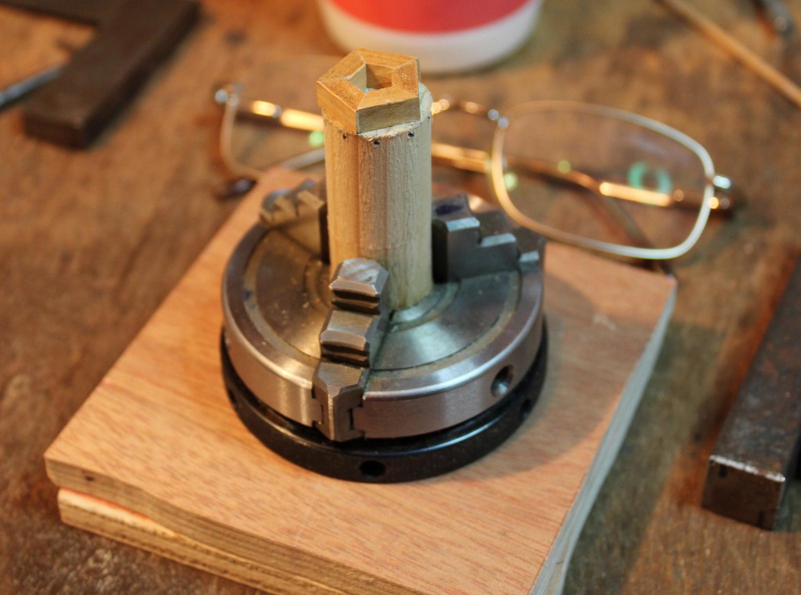
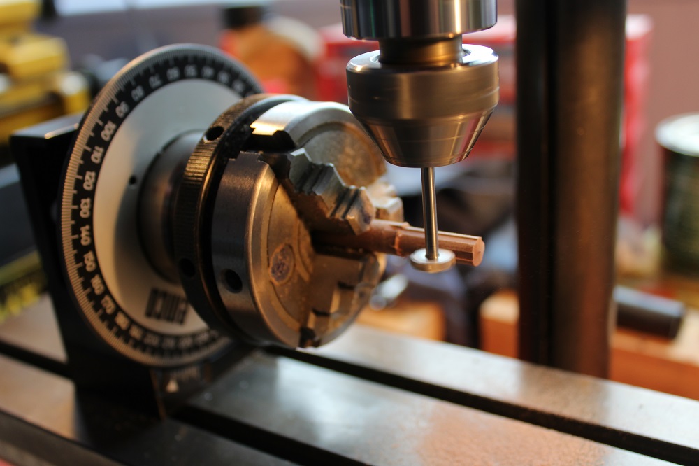
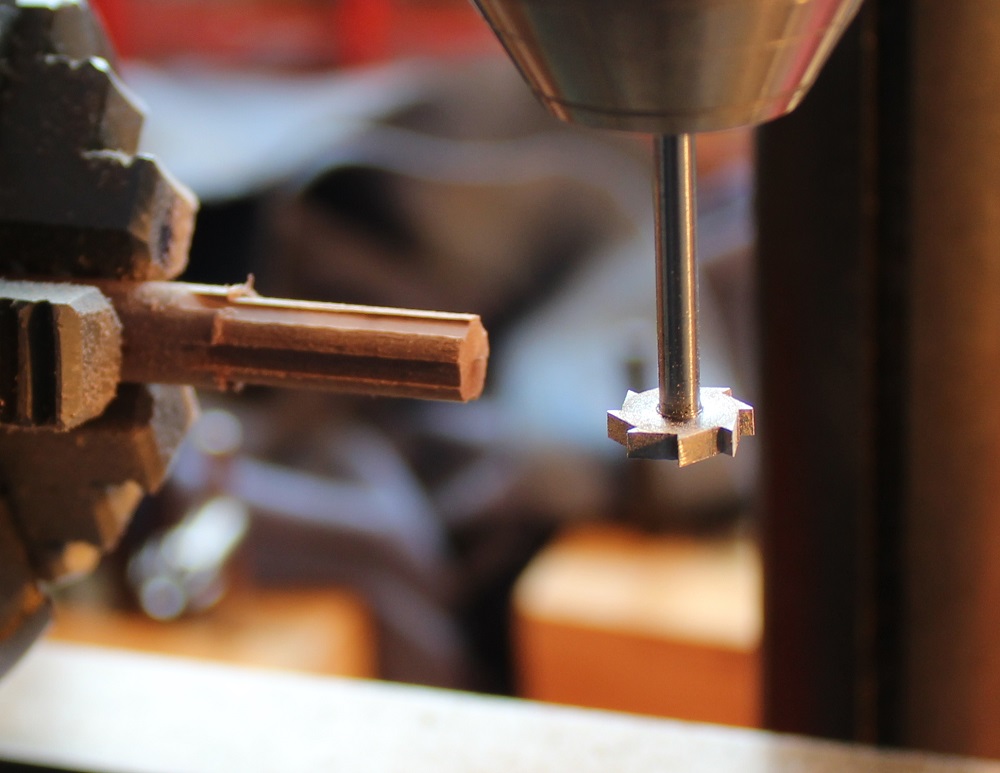
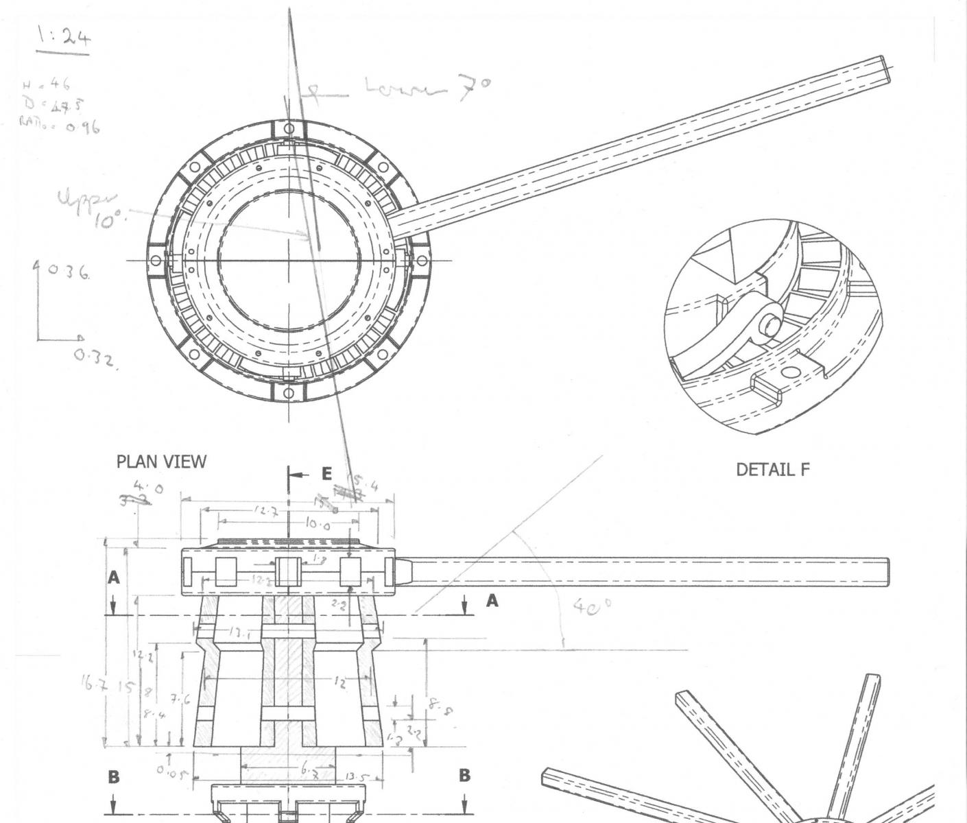
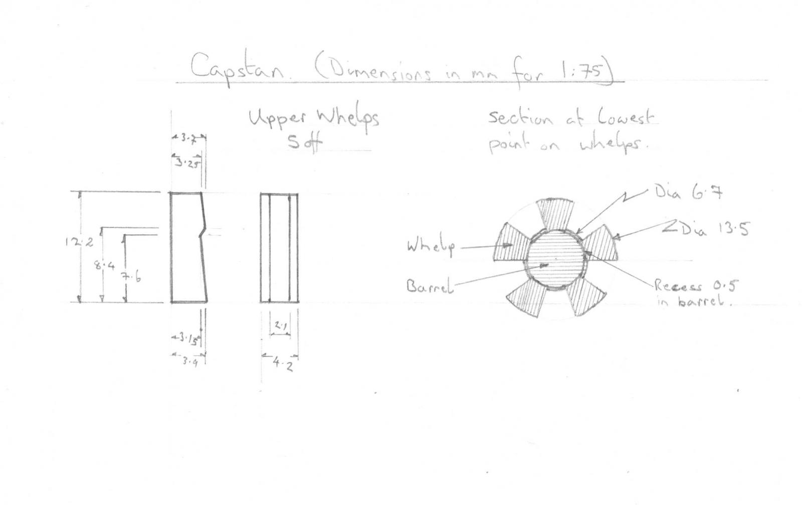
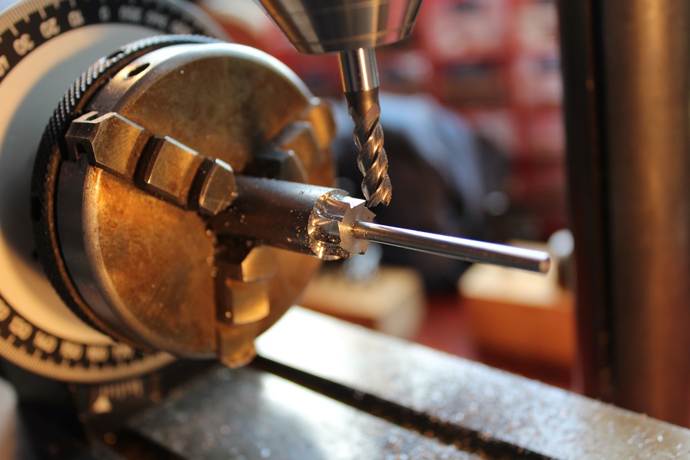
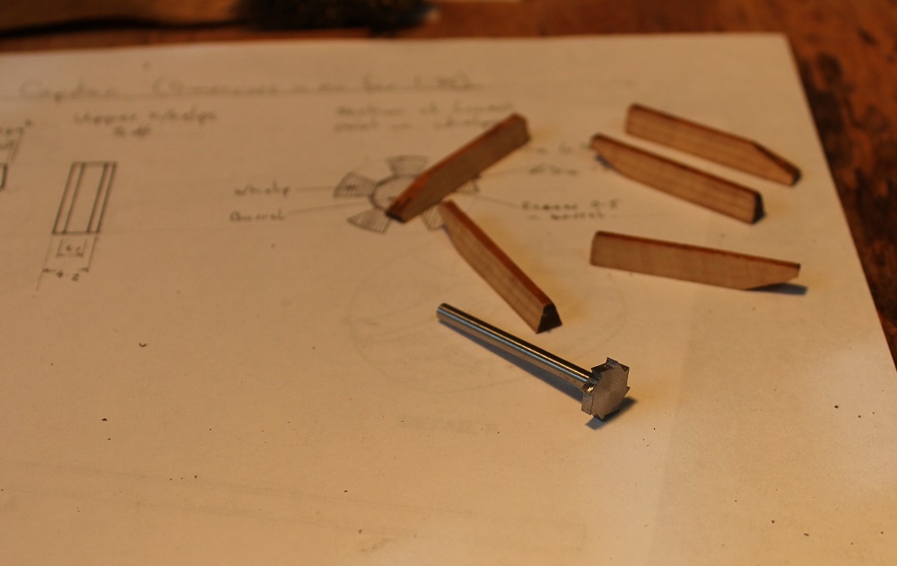
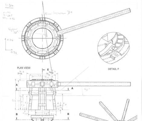
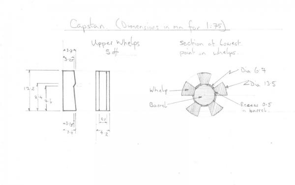
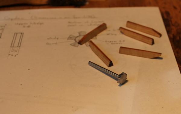
Various non modelling activities have created a 2 month hiatus in my work on the ship but I have had a chance to get back in to the workshop. A belated thanks to Grant, John, David, Mark and Mike for your kind words and encouragement. I got stuck in to the capstan. I used a similar approach to that described by Allan Yedlinsky with a few changes. I marked up a copy of the Rex Boocock plans with dimensions..... ..and produced my own dimensioned cross section plan with whelp shape. First part of construction was to chuck a length of 10mm diameter walnut doweling in the lathe and turned a length of it down to 6.7mm diameter. For the whelps I used boxwood recovered from an old damaged 18" rule. The rule had belonged to my grandfather and was about 70 years old! I don't have a decent small circular saw so I cut the pieces with my powered fretsaw. Rex's plans show 5 whelps which have widths the same as the gap between them. Therefor each whelp would have a 36 degree included angle. So I set the saw's table over to 18 degrees and clamped a piece of wood as a fence and cut the blanks. The good guys shape the outer faces of the whelps at this stage but I left that for now. I wanted 5 off 2.1mm wide slots along the barrel in which the whelps can sit firmly. I haven't got a cutter or milling bit of that size so I made one. Since it is only to be used on wood it didn't have to be anything fancy. I chucked a length of mild steel in the lathe (I have a second chuck so the first still had the wooden barrel). I turned a 42mm length down to 10 mm diameter, then the end 36mm was turned down to 3mm diameter - which is the shaft diameter used for Dremel tools. The chuck was transferred to the dividing head on the milling machine and using a 5mm mill bit I took light cuts at 45 degrees around the mild steel. Before cutting I set the side of the mill bit over the centre line of the work then moved it forward about 0.5mm so that it was slightly off centre. This ensured a reasonable cutting face angle on the new tool. I gradually increased the depth of cut around the tool until the adjacent cuts met. This produced a set of 8 sharp teeth. The work was returned to the lathe where the piece was parted off at 42mm long. The new tool was then held in the chuck by its shaft and faced down until the cutting blades were 2.1mm wide. It is going to be infrequently used on wood so I didn't bother hardening it. The next photo shows the finished tool alongside the whelp blanks.

-
Danny, Beautiful work. You could place it among the models at the NMM and only its dated label would reveal that it was not one of the excellent contemporaries. Once again many thanks for generously sharing your knowledge and techniques - it has been very useful to the Unicorn club!
-
Mike, It is looking very good. I do like your cathead supports - a big improvement.
-
Igor, That is beautiful and amazing. You will have to slow down because I can't keep up with your work - it is so fast! :)
-
Gosh John, that looks rather lovely. It really looks the part. I think using styrene for the stove (or to make other sheet metal items) is a good move. It can be easily embossed to simulate rivet detail or easily built up to represent other surface detail using solvent as a glue. The main downside is that it has to be painted - if you happen to hate painting as I do!
-
Mike, That looks a nice shape and fits in well.
-
Mike, Having fitted carved up lower castings on my galleries I belatedly came to the conclusion I would have been better leaving them off - as other guys have done. They simply don't fit and look clumsy. I managed to pop one of the awkward canon. To get it back I mounted the carriage on the end of a kebab stick with something like blue tack between the carriage sides. A touch of superglue on the bottom of each wheel then jiggled the carriage through the gun port. I then pressed the carriage down with a lollipop stick to get it to bond. The kebab stick and superglue could then be removed freeing up the space for the barrel to be refitted. Any marks left by the blue tack were well hidden. My big fear was that I would lose control of the carriage and it would end up sticking itself somewhere inappropriate and totally inaccessible. Fortunately I avoided that horror.
-
Mike, The material for the catheads was supplied in a single length of 5x5 walnut in my kit. It also had a split in it which fortunately I was able to work around. I took the length from the plan. My kit had the 1974 issue 1 plans which had no front elevation so judging the angle of the catheads was difficult. From the colour of your kit box (blue and grey) your's should have the later versions of the plans which includes a front elevation, so it should be easier to judge. BTW, my early kit box was black and grey.
-
Mike, I cut a square hole in each bulkhead with its leading edge 8mm from the front of the bulkhead. I then filed a taper on the underside of the cathead beam as per the instructions and glued it on top of the deck planking. Two issues:- 1) I didn't taper them enough. I used the supplied supports as guide to filing - their angle is wrong. The result is the catheads are just about horizontal rather then pointing upwards a few degrees. 2) As per the instructions I drilled 4 holes in each cathead - there should be six. The whole of my Unicorn's headworks make me cringe - it was all done some years ago before I found MSW and other on line sources of ship info,
- 51 replies
-
- 1
-
-
- first build
- corel
- (and 1 more)
-
Mike, Your repositioned figurehead is a great improvement. Excellent. Wish I had thought of doing that! One other thing we discussed in this area is that the kit plans show two sets of gammoning on the bowsprit. Only one set is required on a ship of this size which is easier to do.
-
Mike, The Corel idea of the head works in this kit is bizarre to put it mildly. To get a better idea of how the head timbers go together I suggest having a look at Dan Vadas' Vulture log. It gives an excellent step by step approach with some very clear photos. The start of the head works is <here> on page 63 of his log and continues to page 68. Dan's log is my main "go to" being chock full of useful info. For example the latter part of the log has very detailed description of the construction of the masting and rigging.
- 51 replies
-
- 2
-
-
- first build
- corel
- (and 1 more)
-
Joe, I am expecting this to be another fine piece of modelling.
-
Mike, Welcome to the Unicorn club! Your planking looks very good. Are you going to sand the rear most bulkhead to make it more curved. If you look at the plan view of the stern there is quite a pronounced curve. I failed to do this and then had big problems fitting the gallery pieces. It is worth considering adding a stern piece. Have a look at the discussion in landlubber mike's log. Out of interest was it something on the kit that caused you to stop? I had a lengthy break in construction due to insufficient deck planking, plus only 16 wheels being supplied for the canon. Still - found a way through in the end.
-
Alex, Very nice clean metal work. It will look great when it is complete. BTW - I did a double take when I first saw your signature - my eldest son signs himself Alex M as well!
-
ROYAL CAROLINE 1749 by Doris - 1:40 - CARD
ianmajor replied to DORIS's topic in - Build logs for subjects built 1501 - 1750
Phew Doris - your Caroline is out of this world - as are your other ships in the photos. I really can only dream of working at this level. Wonderful. I am looking forward to seeing you applying your skills to the plastic kits - I am sure it will be a revelation. BTW - all the best in your new job.- 883 replies
-
- 4
-
-
- royal caroline
- ship of the line
- (and 1 more)
-
Joe, Love your Granado. It has turned out really well. Great clean piece of craftmanship. Well done.
- 302 replies
-
- 1
-
-
- granado
- caldercraft
- (and 1 more)
-
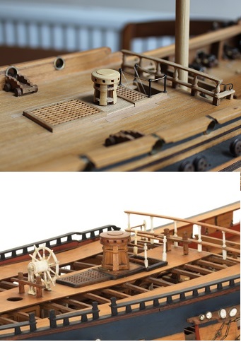
Based on my scaling of Rex's diagram I roughed out a capstan on the lathe from some scrap pine. I tried it for size on the quarter deck. The following shows it sat on the Unicorn with the remains of the Coral version just behind and to the left of it. It looked rather large therefore I went back to the Lyme plans and measured up. The scale sizes in ft and inches for comparison. Corel - Height 3' 0" Diameter 3' 0" Rex's plan - Height 4' 2" Diameter 3' 7" Lyme plans - Height 4' 3" Diameter 3' 9" Which, amazingly, makes the rough capstan approximately the right size. The Corel offering is only 75% of the proper size. Time to start on the detailed version.