Supplies of the Ship Modeler's Handbook are running out. Get your copy NOW before they are gone! Click on photo to order.
×


Stuntflyer
-
Posts
1,197 -
Joined
-
Last visited
Content Type
Profiles
Forums
Gallery
Events
Everything posted by Stuntflyer
-
 Thank you, Frank! Well, for sure I'm no artist so painting the friezes would not be an option for me. Mike
- 607 replies
-
- 1
-

-
- winchelsea
- Syren Ship Model Company
- (and 1 more)
-
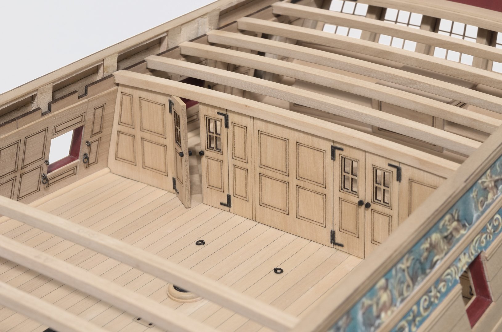
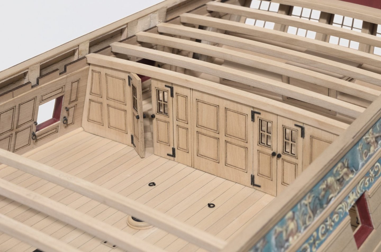
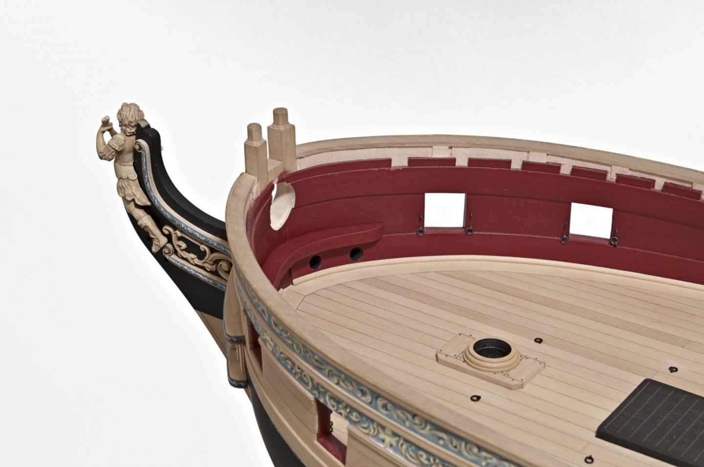
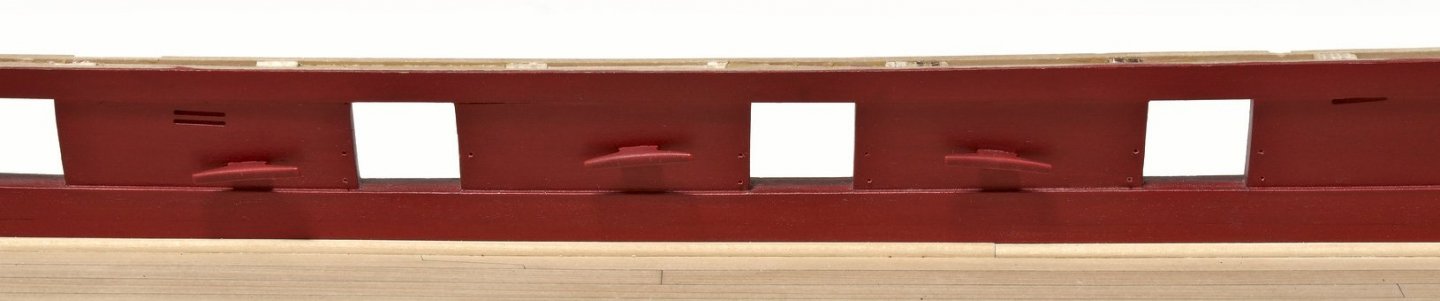
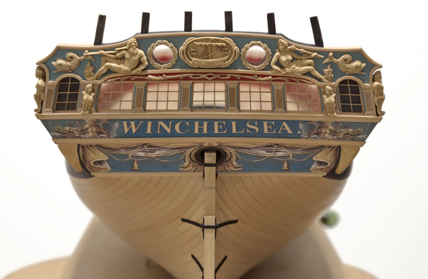
I've started work on some of the deck details starting first by painting the inside of the transom. When I airbrushed the bulwarks there was good control of the color depth and I was able to mask off as well. Not being able to easily mask off the transom area, I decided to use a flat 1/2" stroke brush instead. I started with W&N Crimson for several coats, followed by my usual 10:1 Crimson and Burnt Umber. This gave me better control over the darker tone while making sure that the color didn't get too dark. I removed all of the char from the Quarter Gallery beams except for the bottom edges. After fitting all of them in place they were numbered from 1-20. The last beam that goes against the transom had to be scratch built. The shape of my transom and the supplied laser cut beams didn't match up well and I wasn't going to try to edge bend them into shape. I moved onto assembling the bulkhead at the great cabin. I decided to leave one door open. The three exposed edges of the door were painted to better match its overall color. I didn't paint to a perfectly even color. Instead I left the darker color showing through in places in order to simulate wear and tear that might occur during normal use. The top corner of the door is glued to the beam above to help keep it in open position. I added the two gun port lids that will remain closed at the cabin. Also, I removed the rudder due to the pintel at the top breaking when I accidentally pushed the rudder too far. I was able to remove it without removing the top of the rudder trunk. Once it was off the ship it was easy to fix. I removed just enough off the top of the rudder in order to make it possible to push it up high enough to clear the pins. The top of the rudder still cannot be seen when it is in place. I will put the rudder on when I feel it is safe to do so. No harm done! Mike
- 607 replies
-
- 27
-
-
- winchelsea
- Syren Ship Model Company
- (and 1 more)
-
Nope! I won't be putting them on the Winnie. I see that your working on your own Winnie. Will we ever see photos of your progress? Mike
- 607 replies
-
- 2
-
-
- winchelsea
- Syren Ship Model Company
- (and 1 more)
-
Matthias, Areas of the figureheads lower back where removed in order to get it to sit close to the forward edge of the stem? The stem was left untouched. The cheeks and hair brackets were added to the model before any of the friezes were applied. Mike
- 607 replies
-
- 3
-
-
- winchelsea
- Syren Ship Model Company
- (and 1 more)
-
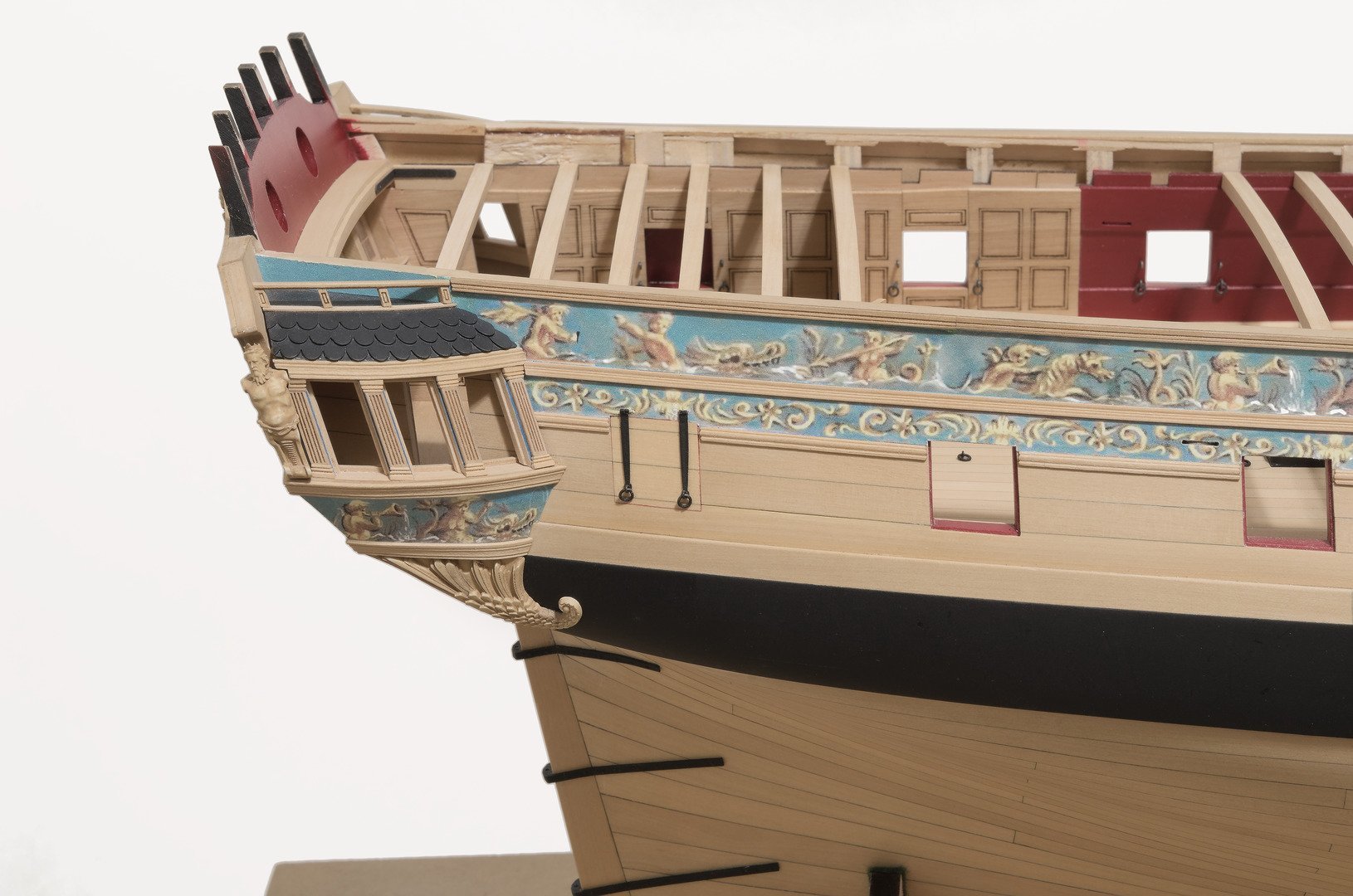
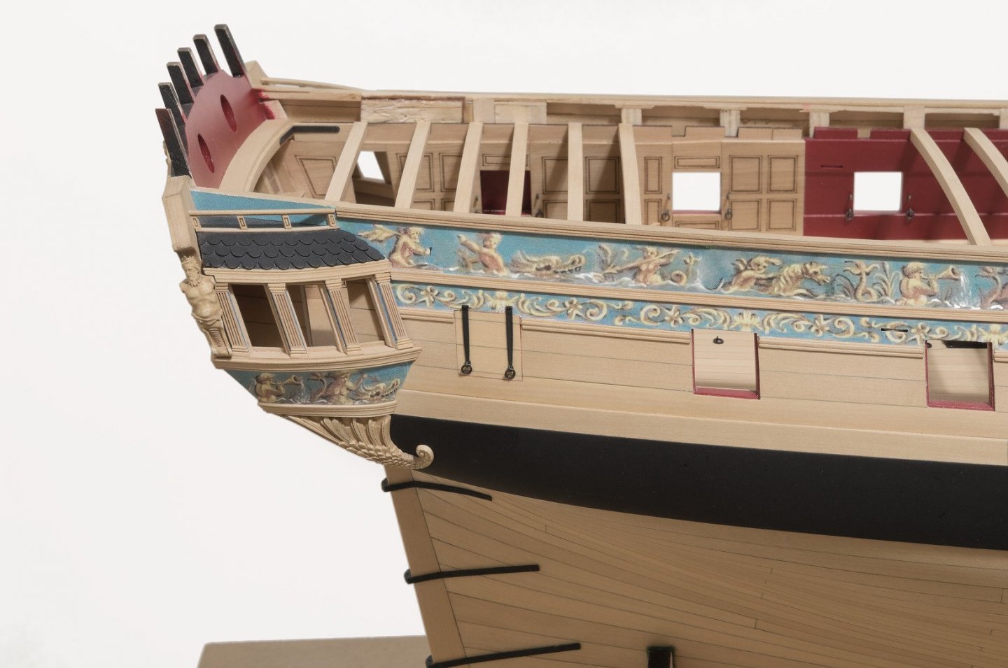
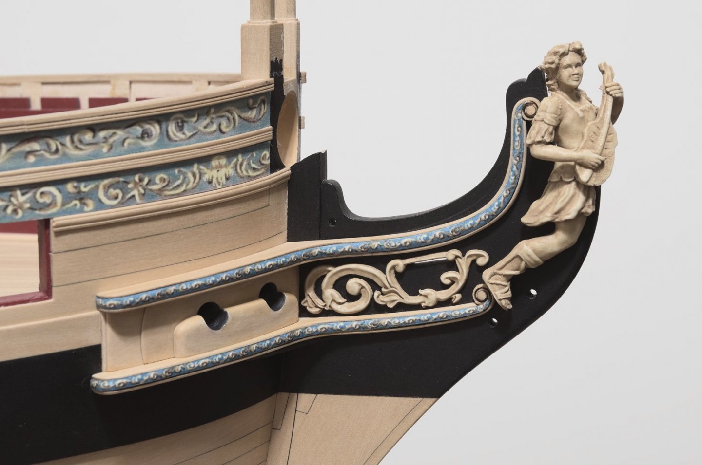
Well, here goes another update. . . Not a small task was completing the work on the cheeks and hair brackets. Rather than repeat what Chuck has already described it might be useful to mention a few things I did, including some observations, while completing the work. After assembling the four cheeks, the outer two layers were thinned down even more. I would say that I removed about 1/64" overall Before rounding off the center insert for the hair brackets, I lowered its profile a bit before rounding off. If it's too round the frieze won't span its width. I did not use the three laser cut pieces which go between the cheeks. They were about 1/64” short in height on my ship and I didn’t want any gaps showing at the outer end between the cheeks. Luckily, I had some .025 boxwood sheet from a previous build. The bolster was scratched as well. Drilling the hawse holes at an upward angle is crucial. I recommend filing the holes from both directions. After adding the bolster it was easy enough to cleanup the transition between the hawse holes and bolster with some wood filler. Prior to adding the friezes, I painted the paper edge with un-thinned POLY Scale Dark Green 414272 which I found to be a close overall match. My suggestion when adding the friezes to the cheeks and hair brackets would be to do that after those pieces are glued in place. Even though the friezes overlap, establishing the proper length in order to match the frieze pattern should not be too difficult to do. The wash cants were added after painting them black. I think I'm going to add the short decorative molding along the front of the figures leg after the figure is glued in place. There was what seemed like an endless amount of fitting, adjusting and more fitting needed in order to get all the parts working together. Getting both feet of the figurehead to sit against the hair bracket was tricky. The joints between the cheeks and hair bracket as well as a uniform tapering of those parts all required some of extra work. Even the angle of the carving had to be tweaked. No rushing here, at all! The knee was made by first shaping one side and then pinning that side temporarily to the hull. This was done in order to make it easier to fit the other half to it. Using a hand turned disk sander with tilt table makes it easier to get the angle just right between the two halves. The finished knee was painted off the ship. Mike
- 607 replies
-
- 20
-
-
- winchelsea
- Syren Ship Model Company
- (and 1 more)
-
Looking really nice, Ben. Lining off pays off. Mike
- 399 replies
-
- 3
-
-
- winchelsea
- Syren Ship Model Company
- (and 1 more)
-
Here you go. . https://www.micromark.com/Doc-ObrienS-Powders
- 1,784 replies
-
- 1
-
-
- winchelsea
- Syren Ship Model Company
- (and 1 more)
-
I've been waiting patiently for a Saturday get-together. They are always lots of fun and it will be great to see everyone. As much as I worry about packing it safely into the car, I will bring the Winnie. M
- 1,784 replies
-
- 3
-
-
- winchelsea
- Syren Ship Model Company
- (and 1 more)
-
Nice work, Frank! Are the two battens at the same position, height wise, at the stem? Mike
-
Yes, that's basically how I do it. I wrap the wire around the shank of a drill bit and then use a very fine blade on a fret saw to separate the rings. Mike
- 607 replies
-
- 3
-
-
- winchelsea
- Syren Ship Model Company
- (and 1 more)
-
The eyebolts and split rings for the bulwarks and gun deck are done. Boy! I just love making those🤥 I made them as small as I could. The ID the bolts are around .025" which conforms to the smallest round nose pliar that I have. Just enough to get the 24ga rings through. Be careful not to drill too deep into the bulwarks against the plywood bulkheads. It wouldn't be hard to snap a bit if you did. Mike

- 607 replies
-
- 22
-
-
- winchelsea
- Syren Ship Model Company
- (and 1 more)
-
Looking quite nice, Rusty! Interesting colors too. Mike
- 642 replies
-
- 2
-
-
- winchelsea
- Syren Ship Model Company
- (and 1 more)
-
Thanks, Matt, I'd gladly do those lids anytime over having to do those pesky window sills. They were a pain!
- 607 replies
-
- 3
-
-
- winchelsea
- Syren Ship Model Company
- (and 1 more)
-
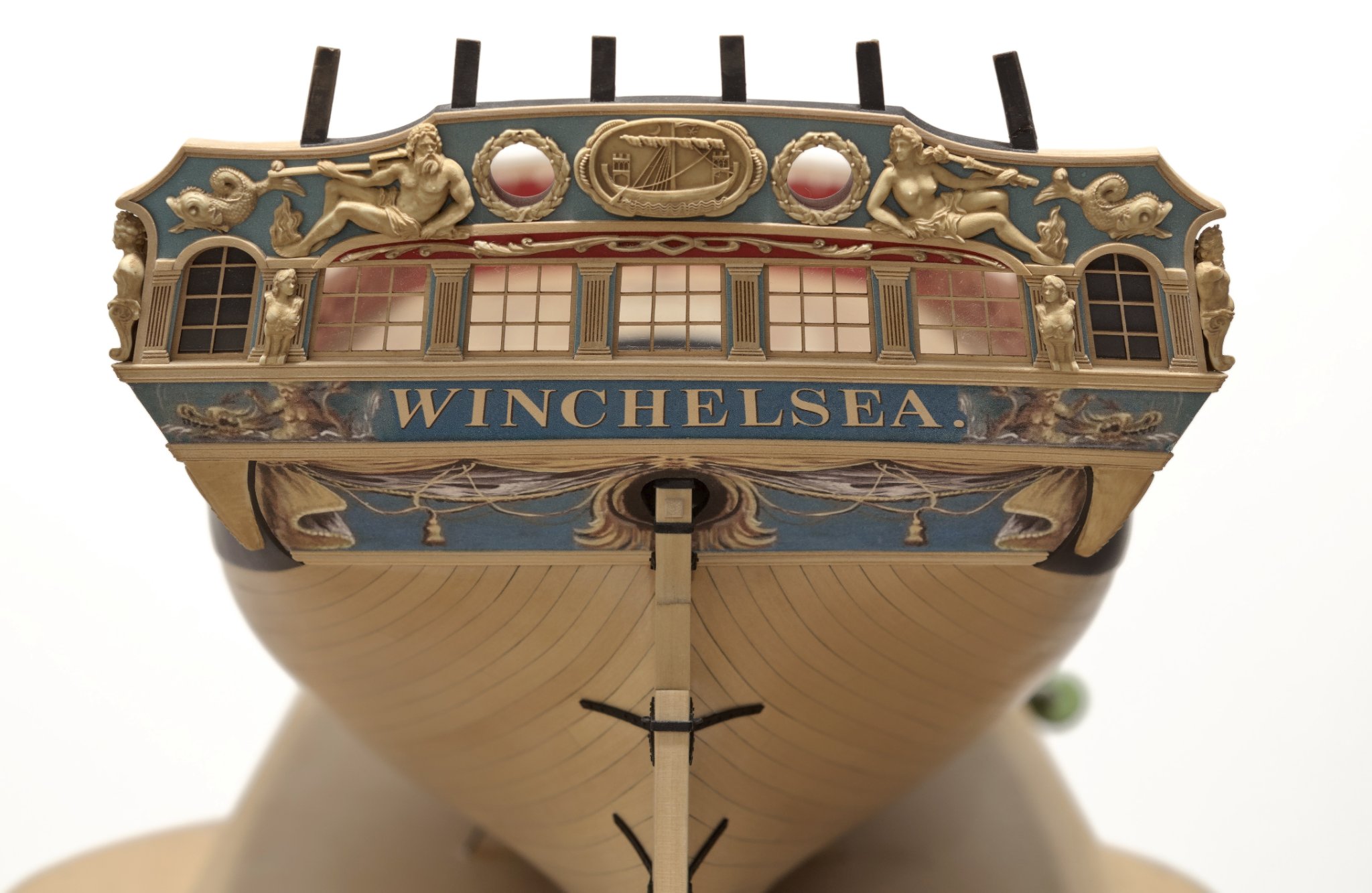
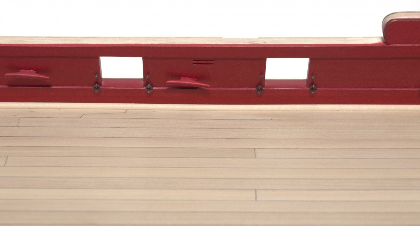
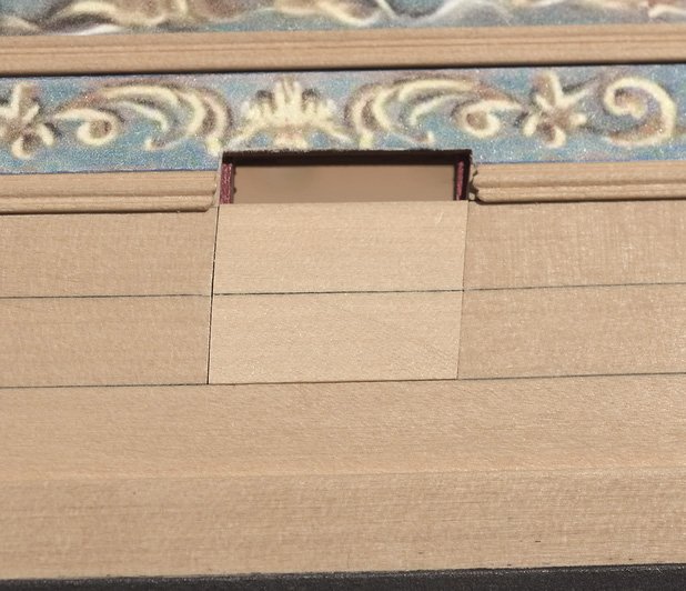
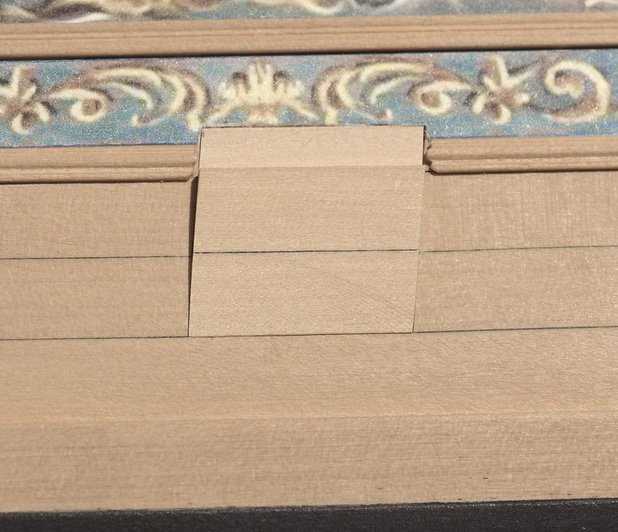
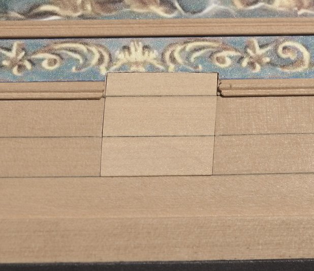
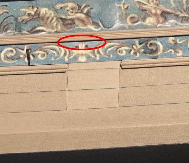
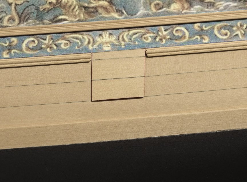
I thought it might be a good time to get this post in as it covers a number of tasks that I've been working on. Starting with the gun port lids. The first step was to get these two planks fitting correctly The last plank is placed underneath so that the bottom edge can be traced The final result with all three planks in place When adding the frieze, the top section is cut away so it can be registered with the frieze below. Final result with lid lining attached, painted and ready for hinge Pinned cleats to the bulwarks. Transom windows and sills Mike
- 607 replies
-
- 35
-
-
- winchelsea
- Syren Ship Model Company
- (and 1 more)
-
Chuck, How many of hanging knees need to be made? Mike
-
All the more reason now to keep things neat down below.
- 1,784 replies
-
- 4
-
-
- winchelsea
- Syren Ship Model Company
- (and 1 more)
-
Nice, Chuck! That's an improvement from the last template I saw the other day at your place. The one that made it difficult to see anything down below. Mike
- 1,784 replies
-
- 1
-
-
- winchelsea
- Syren Ship Model Company
- (and 1 more)
-
They do, though slight variations from those marks might occur when you set the batten. So, use the marks as a guide. Mike
-
Thank you all for the comments and likes. Very much appreciated! Mike
- 607 replies
-
- 1
-
-
- winchelsea
- Syren Ship Model Company
- (and 1 more)
-
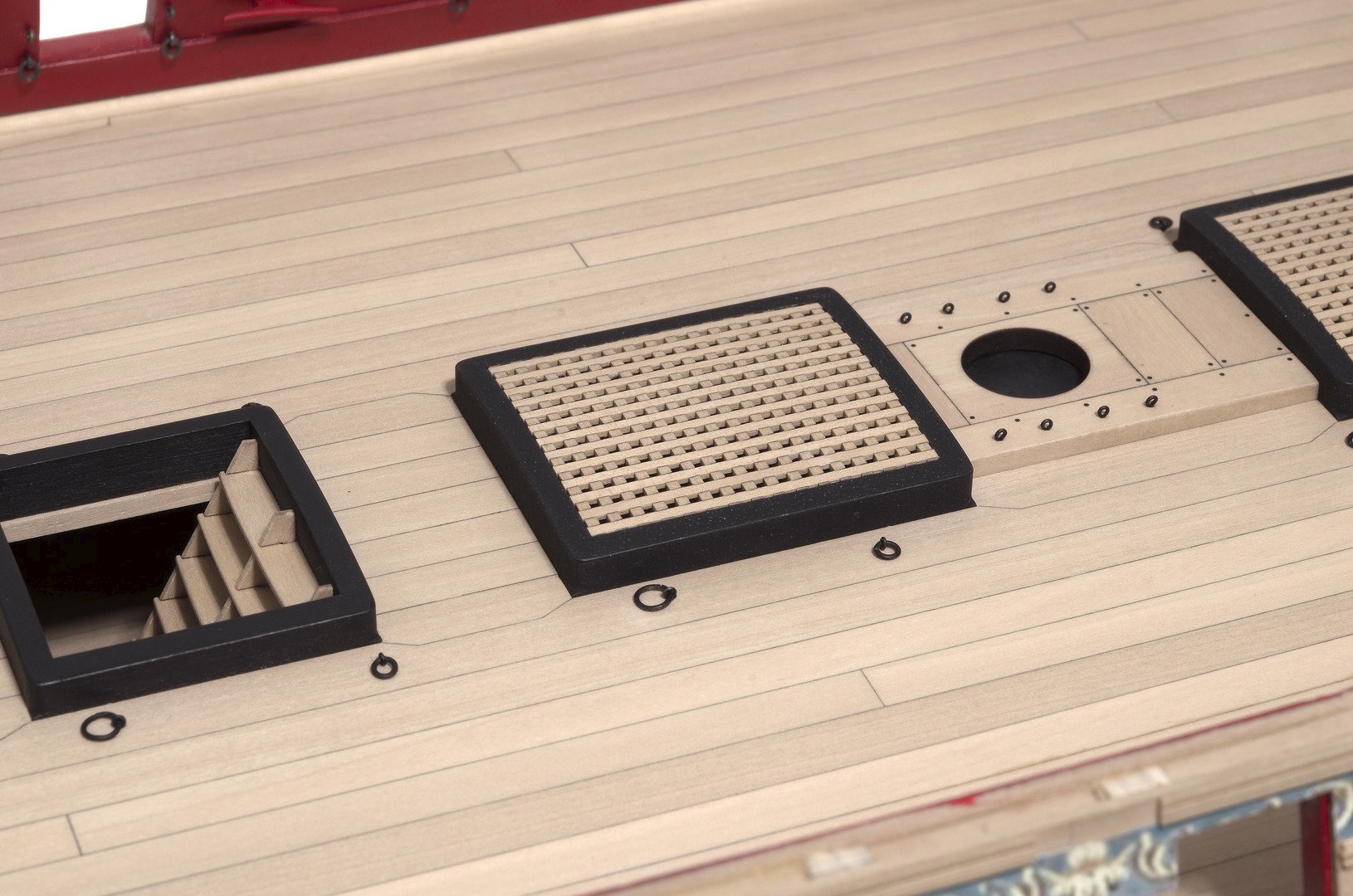
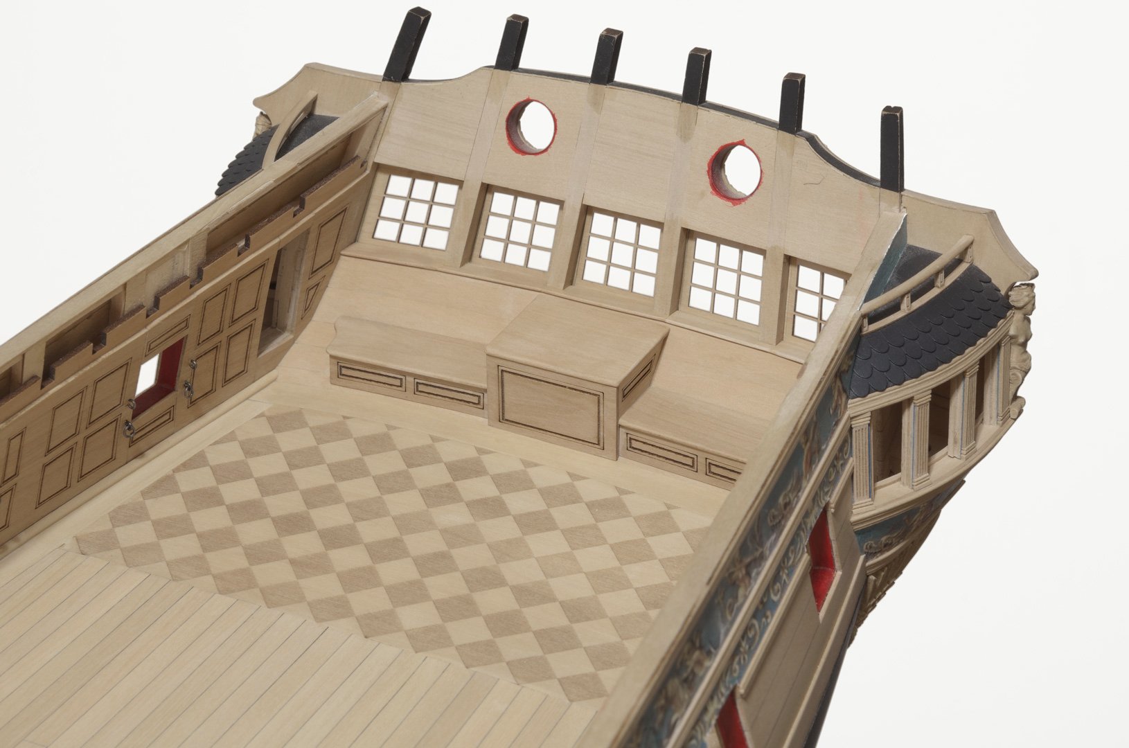
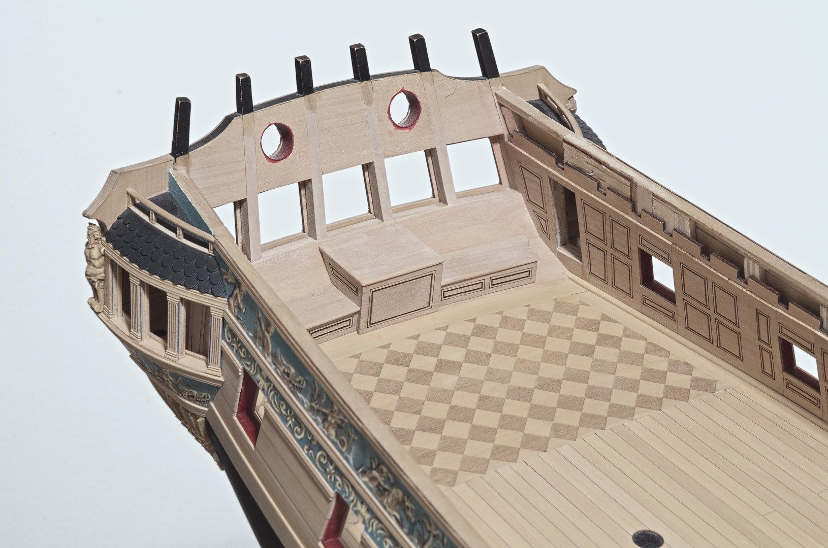
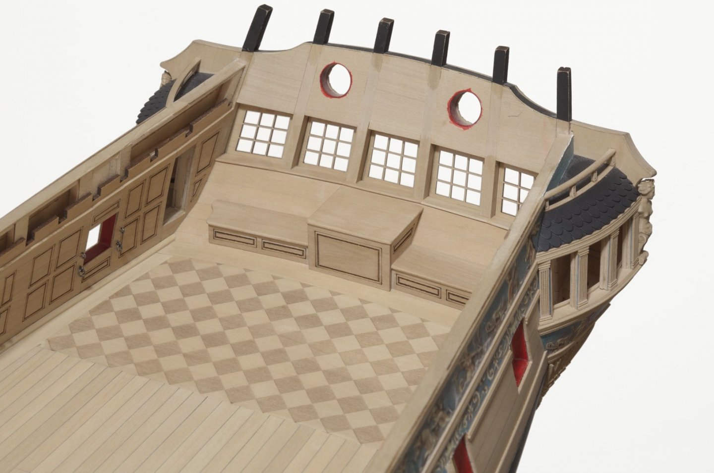
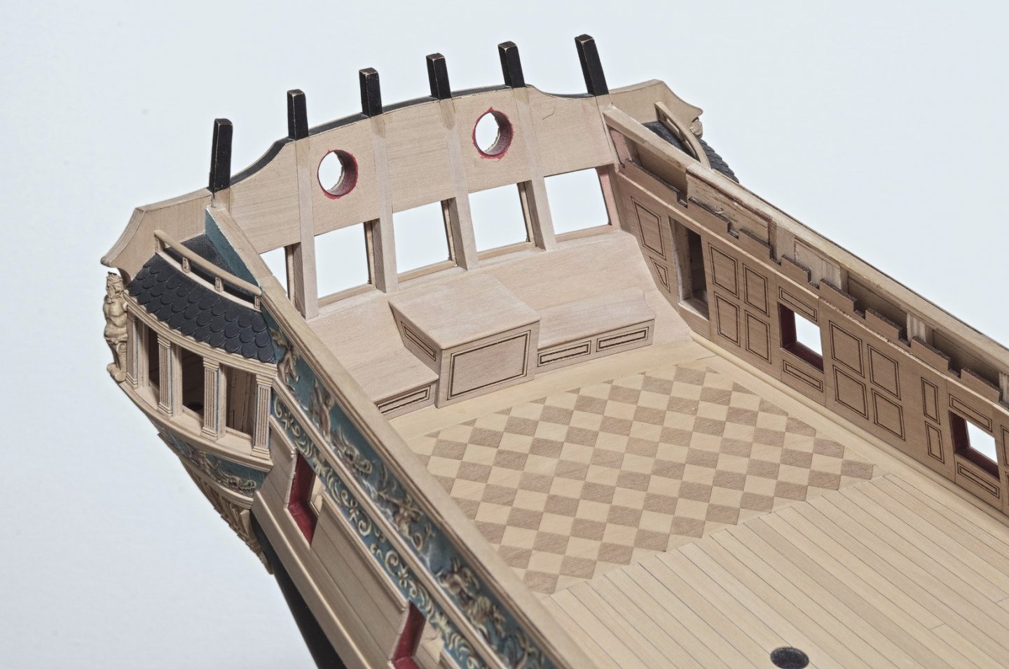
Over the weekend I worked on the rudder trunk and benches. Of course, Chuck's laser cut parts made things relatively easy. The tricky part was getting a tight fit between all the parts. The top of the rudder trunk needs to be angled where it sits up against the transom. I had to sand the bevel almost to a point in order to get a clean joint. When it came time to add the benches, I found that I needed to sand the bottoms slightly curved in order to match the camber in the margin plank. Further adjustments were made to insure that the benches did not sit on the deck. Mike
- 607 replies
-
- 26
-
-
- winchelsea
- Syren Ship Model Company
- (and 1 more)
-
How time flies! It's been over three years since I seized a block. I would have to start making them again so as to remember the way I did them. Sorry I couldn't be more helpful. Mike