Stuntflyer
-
Posts
1,198 -
Joined
-
Last visited
Content Type
Profiles
Forums
Gallery
Events
Everything posted by Stuntflyer
-
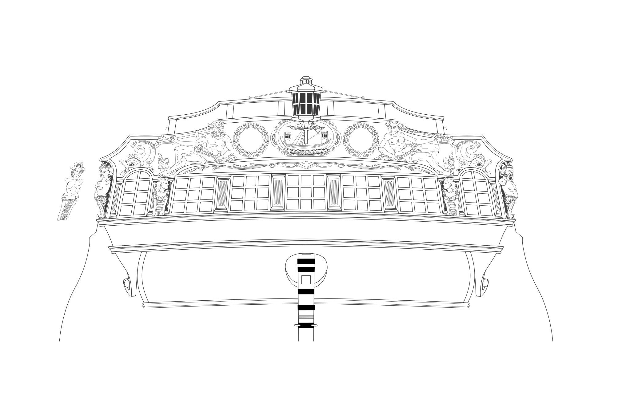
 Since you have already started to plank the lower counter there is a good chance that your width so far is different than anyone else’s. I would suggest that you refer to Chucks log to see how far down you should go with the planking and just use whatever widths would be necessary in order to achieve that. Mike
 -
Happy holidays, Frank! I suppose it doesn’t matter but I’m just wondering why you didn’t correct the over sanded area on the two stern frames before adding the lower counter planking? That way the lower counter planking would cover the edge of those filler planks that you want to add. Mike
-
I think it looks great! I really like the shape work on the uprights. Mike
- 1,784 replies
-
- 1
-

-
- winchelsea
- Syren Ship Model Company
- (and 1 more)
-
Frank, If you take the time to fix it now it will save you a few potential headaches down the road. As Ben mentioned, the frieze will fit better. Also, it will be much easier to get the drop that sits below the Quarter Galleries to fit against the hull. Mike
-
Frank, I got by here, but I did round off the bottom of the lower counter a bit to much. Refer to the plans to see the desired shape. You don't need to worry about the frieze fitting. Just try to shape the lower counter close to what is shown on the the plan drawing, Mike
-
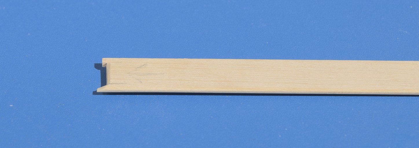
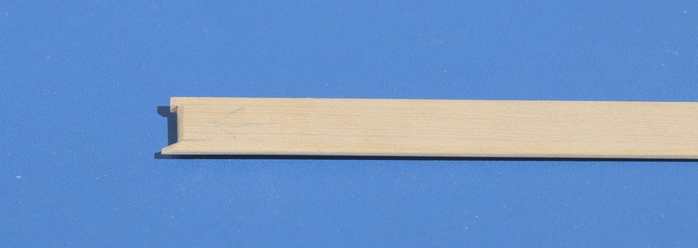
Work continues on chapter nine with some of the forecastle planking completed. W-O-P has not been applied which makes it harder to see the butt joints. Hopefully you will see enough to get the idea. That center piece behind the bollards was made that way which makes it easier to hold. The grain runs port and starboard. This makes it easier to slice off that long tab after the glue dries. Mike

- 607 replies
-
- 25
-
-

-
- winchelsea
- Syren Ship Model Company
- (and 1 more)
-
Ben, I agree with you. 1:48 is the way to go. Mike
- 1,784 replies
-
- 8
-
-
- winchelsea
- Syren Ship Model Company
- (and 1 more)
-
I'm in on the POF build as soon as the Winnie is completed. I would probably go with boxwood. Don't want to burn up the laser which means I would have to scratch the framing. I'm looking forward to that. Exciting stuff ahead! Mike
- 1,784 replies
-
- 2
-
-
- winchelsea
- Syren Ship Model Company
- (and 1 more)
-
Just my older Nikon D5100 with a 60mm f/2.8 macro lens. A tripod of course. Mike
- 607 replies
-
- 4
-
-
- winchelsea
- Syren Ship Model Company
- (and 1 more)
-
Glenn, I used the Fruitwood gel stain. If you brush it on and then rub it off with your thumb, it won't "cake". Just leave enough on to get a change of color. You would be putting it on very thin so maybe two applications would be enough. Btw; using your finger to rub it off is a good way to leave the majority of the color in the recesses of the figure. It will give the figure a more three dimensional look. Mike
- 642 replies
-
- 4
-
-
- winchelsea
- Syren Ship Model Company
- (and 1 more)
-
Yup! Your the first one to spot that. Those areas will be where the fenders are going. Mike
- 607 replies
-
- 3
-
-
- winchelsea
- Syren Ship Model Company
- (and 1 more)
-
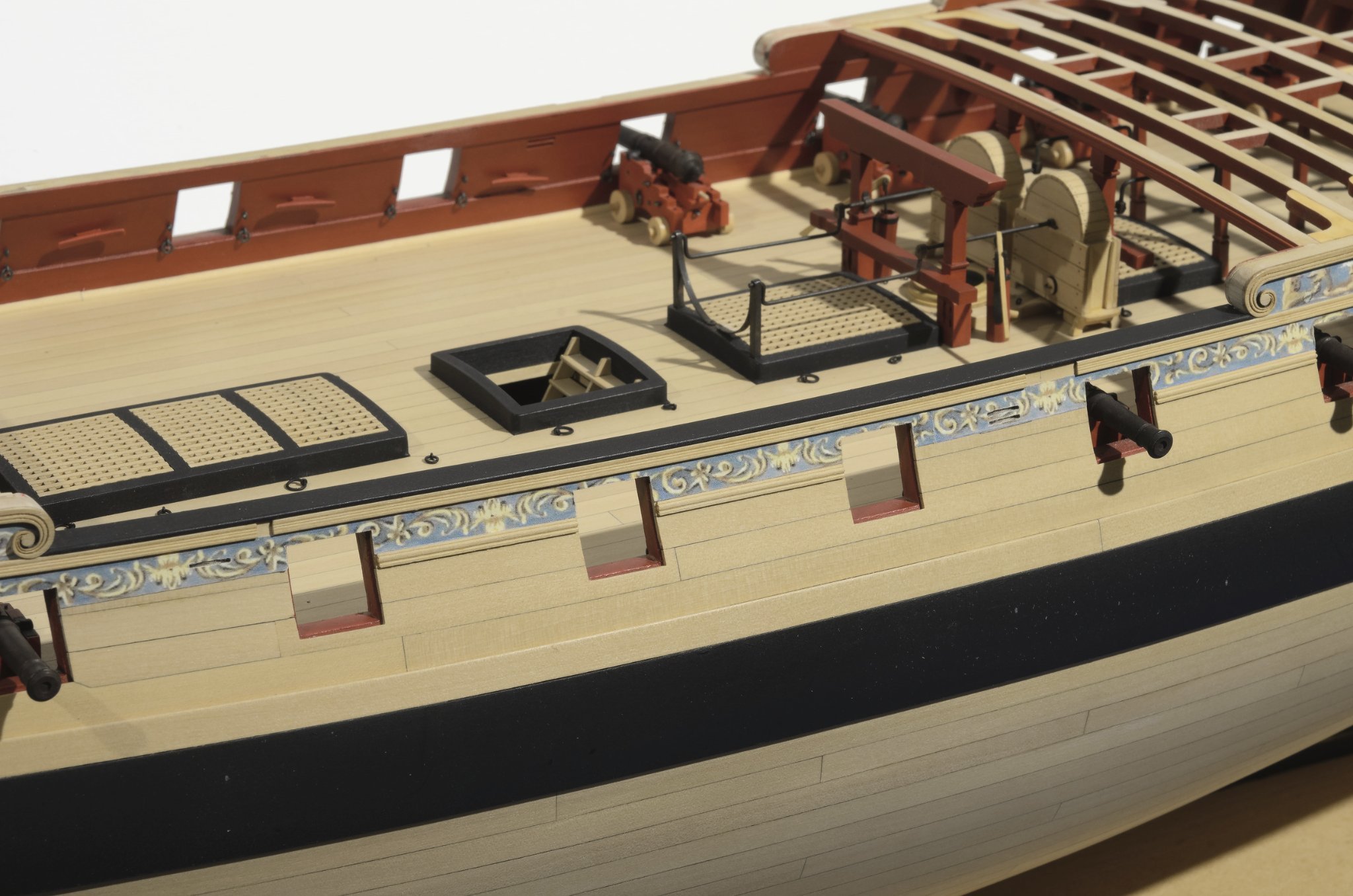
Moving onto chapter 9, I decided to start with the caprail along the waist. I've completed one side. What's interesting is what I had to do in order to get the caprail close to the scroll molding which it sits against at both ends. It was tricky and took some time to do. I'm happy with the result. Each end had to be shaped like this. . Mike

- 607 replies
-
- 18
-
-
-
- winchelsea
- Syren Ship Model Company
- (and 1 more)
-
Glenn, Tom, Thomas, Thank you very much! Mike
- 607 replies
-
- 2
-
-
- winchelsea
- Syren Ship Model Company
- (and 1 more)
-
With chapter eight completed I thought it would be a good time to post some photos. Please excuse the dust. Mike

- 607 replies
-
- 25
-
-
-
- winchelsea
- Syren Ship Model Company
- (and 1 more)
-
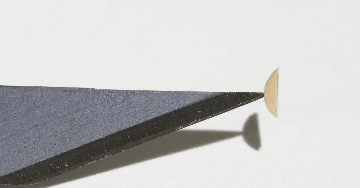
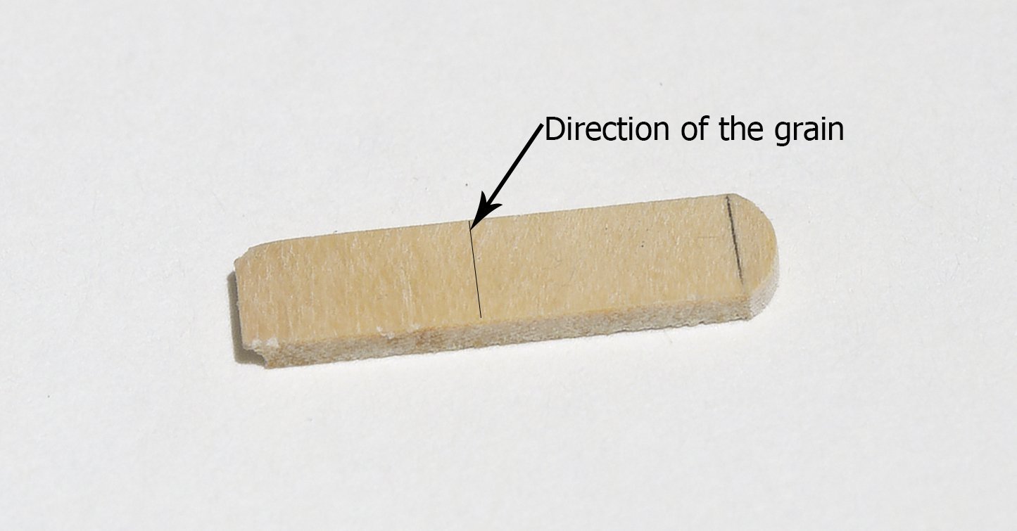
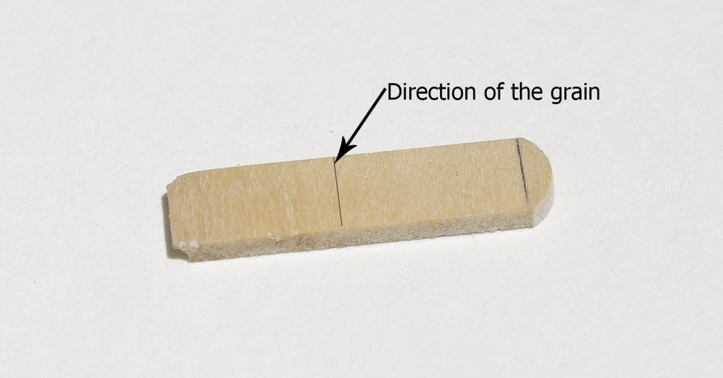
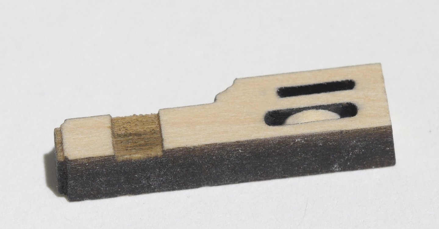
Fore bitt sheaves: Rather than trying to round off the existing laser cut sheave slots, I prefer to simulate the sheaves with wooded disks. There are 2 sheave slots on these bitts. One is 1/32" wide and the other is 3/64" wide. I used "plastic cutting" end mills to deepen the slots an additional 3/32". This allows for the disk to be recessed slightly after being inserted into the slot. Though not essential, I find that a milling machine makes things a lot easier when doing this kind of work. The diameter of the disks are equal to the length of the slot between the sheave holes. The thickness of the disks are the same as the width of the milled slot. This allows for a press fit into the slot without any gluing being necessary. If for some reason they are a tad loose going in, just brush in some W-O-P in order to hold the disk in place. After inserting the disk, the inside area should be painted black. Any paint that gets onto the face of the bitt can be sanded or scraped off easily with a #11 blade. For added protection you could give the outer area a coat of W-O-P to prevent the paint from seeping into the wood. The slot has been deepened an additional 3/32" which allows the disk to recess below the face of the bitt Note the orientation of the grain. This makes it easy to slice off the tiny section of the disk with a #11 blade. A helping hand to insert the disk into the slot Mike

- 607 replies
-
- 5
-
-
- winchelsea
- Syren Ship Model Company
- (and 1 more)
-
Hi Steve, That’s interesting what you did with those stiffeners. Mike
-
Using Windsor and Newton, I mixed some yellow ochre, Raw sienna and burnt umber into white until the desired boxwood color was achieved.
- 607 replies
-
- 5
-
-
- winchelsea
- Syren Ship Model Company
- (and 1 more)
-
I would be very disappointed if you decided to ease up on the level of detail that you have put into the parts for this build. Mike
- 1,784 replies
-
- 8
-
-
- winchelsea
- Syren Ship Model Company
- (and 1 more)
-
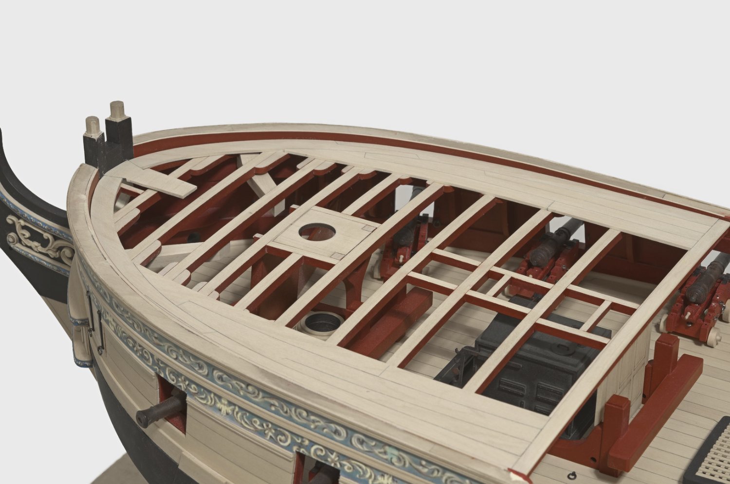
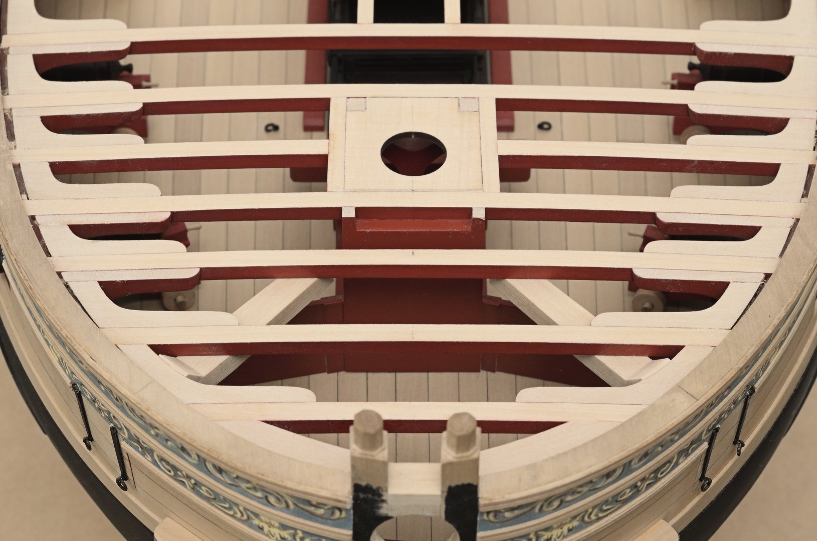
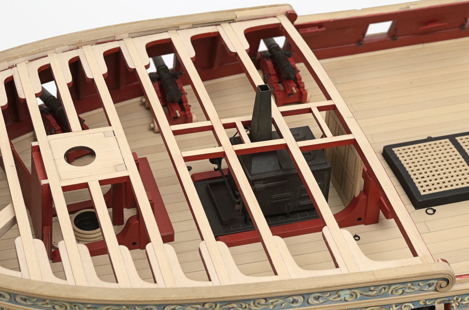
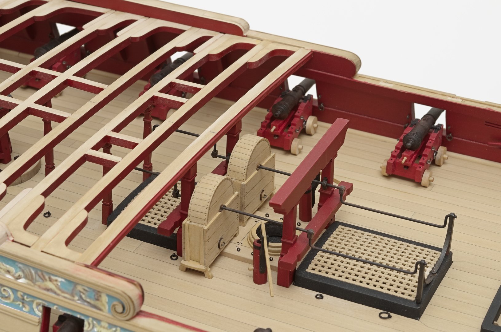
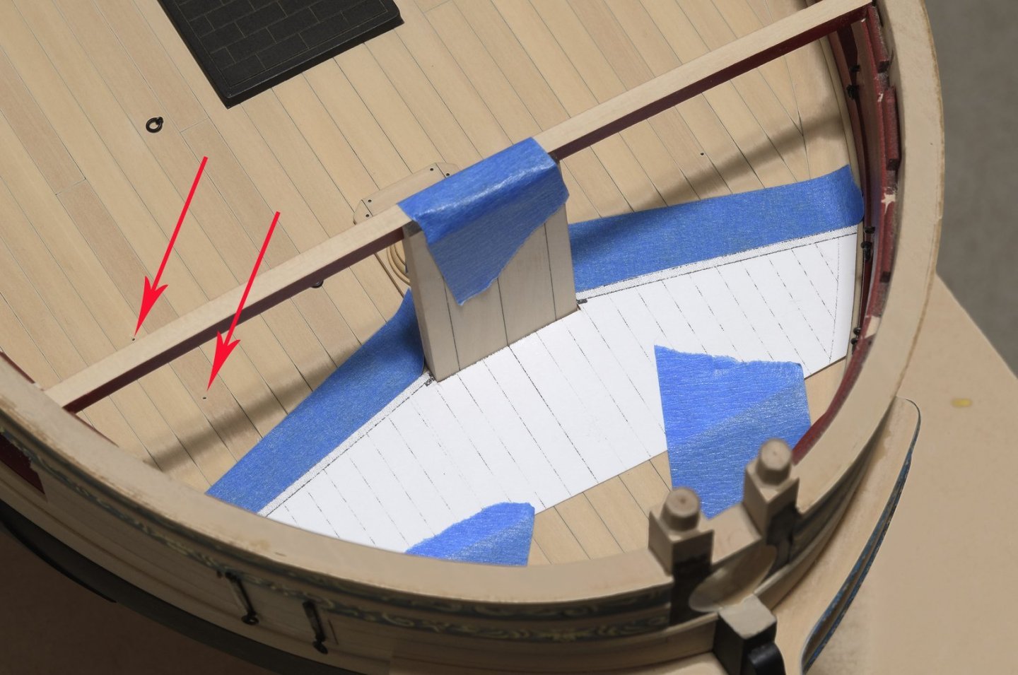
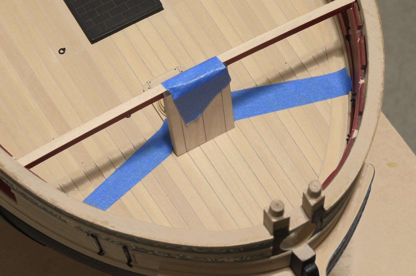
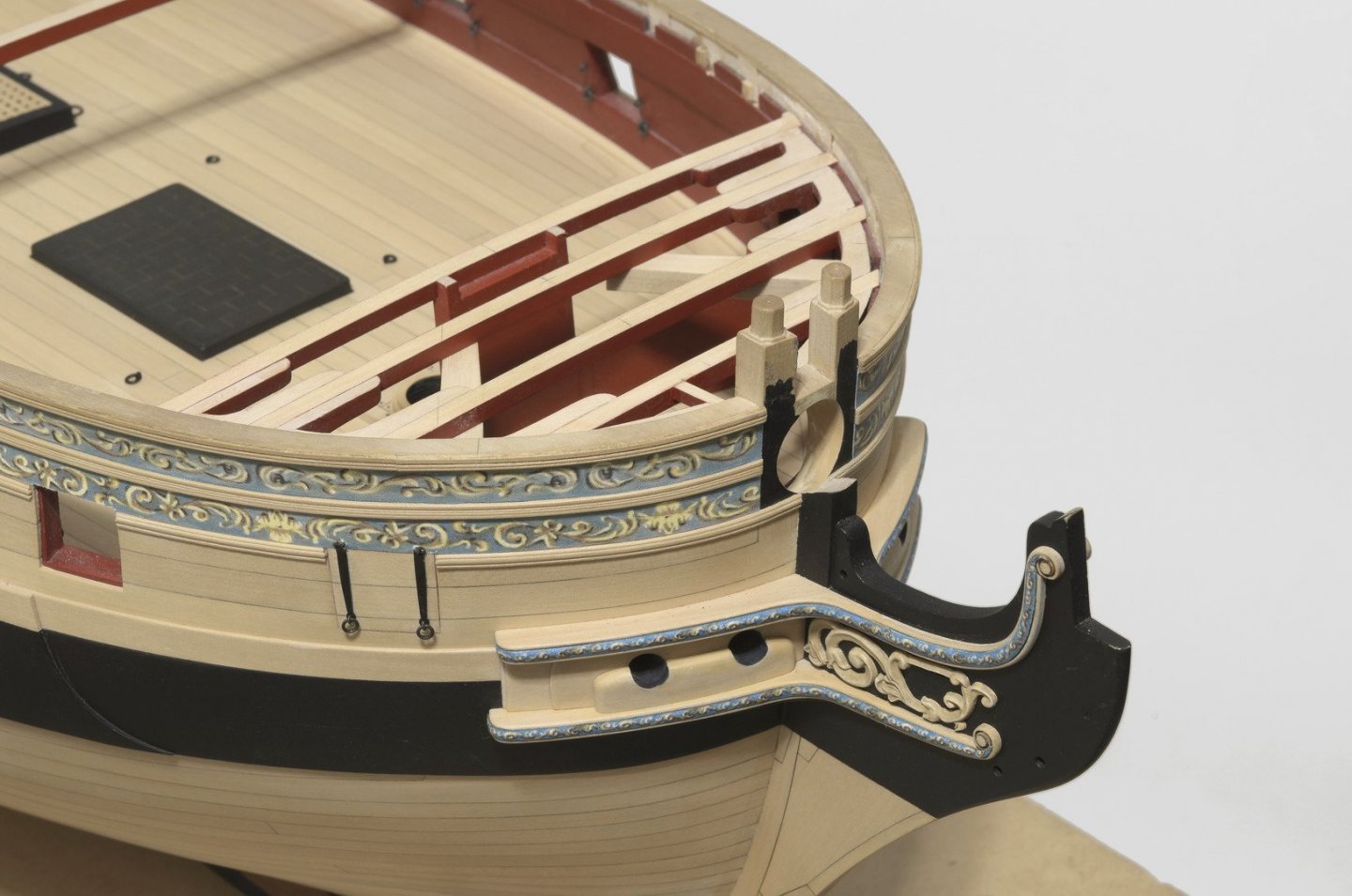
The QD guns are smaller. I started working on the forecastle area of the ship. The first four beams are in along with lodging knees, hanging knees, carlings, cat tails and the manger. To my count there were 32 individual pieces needed for the work so far. The manger which consists of 12 pieces was assembled as one. A card stock template along with layered blue masking tape was used to establish the location for the boards which will sit on the deck. Btw, those char lines on the bowsprit step are no longer visible. They were blocked out with some boxwood color mix that was applied before painting the manger red. Also, those arrows show where I drilled for the next gun carriage. Mike

- 607 replies
-
- 28
-
-
-
- winchelsea
- Syren Ship Model Company
- (and 1 more)
-
Nice progress and beautiful work as always. Attention to detail makes all the difference. Mike
-
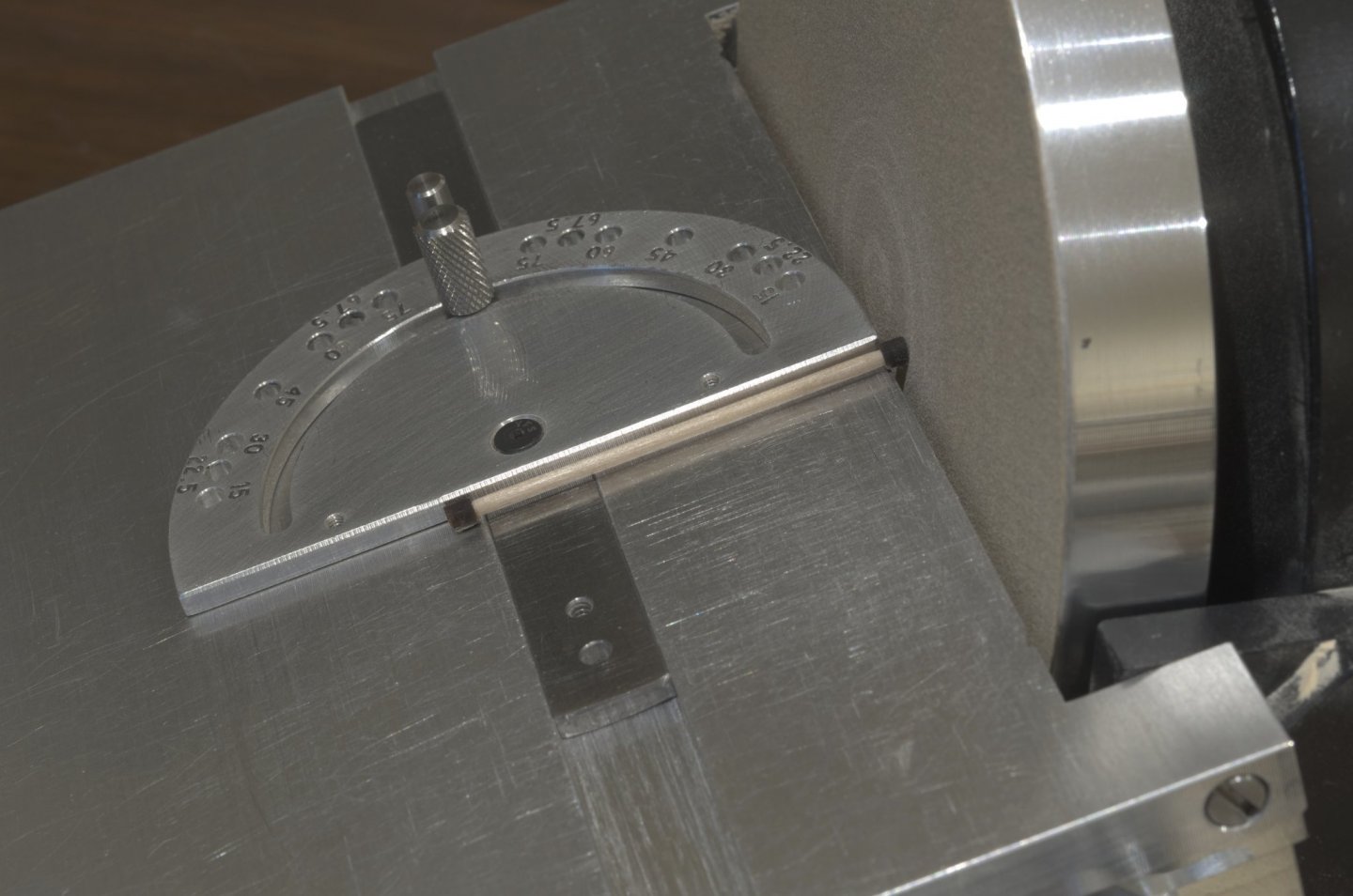
I forgot to mention this in my last post. . I made the angle for the drain pipes by placing a drain on each side of a toothpick and then sanded the desired angle. Mike
- 607 replies
-
- 3
-
-
- winchelsea
- Syren Ship Model Company
- (and 1 more)
-
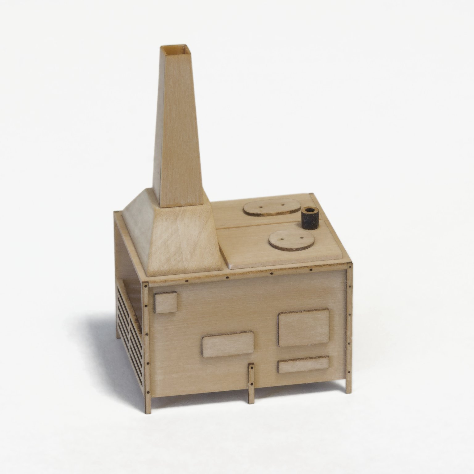
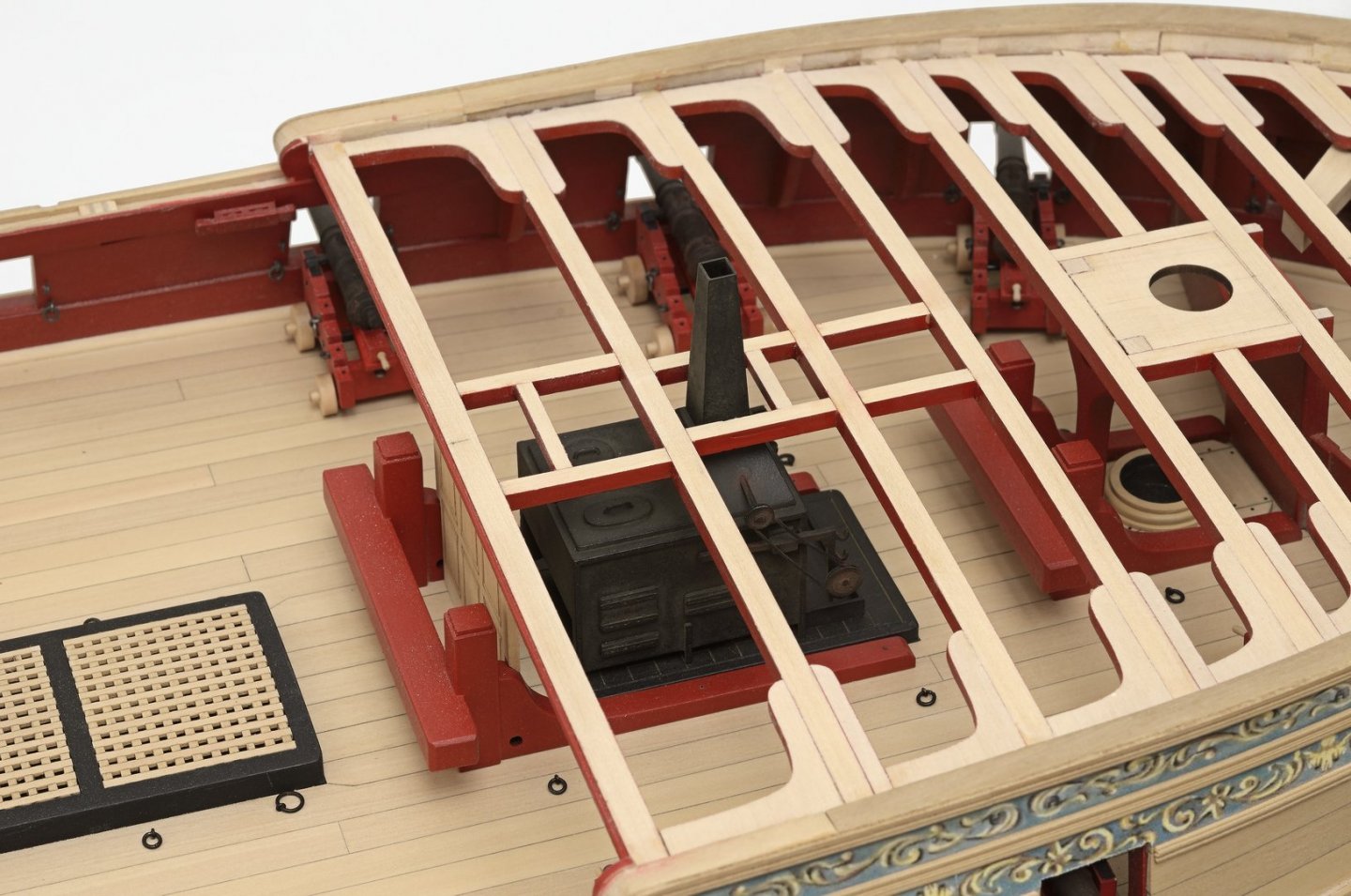
Been working on the stove kit. Just want to say that Chuck has done a masterful job of precision cutting these parts. Everything fits with little or no sanding required. The stack has been thinned down at the top to about 1/64". I forgot to photograph the drain pan. Anyway, here it is ready for paint. Mike

- 607 replies
-
- 14
-
-
- winchelsea
- Syren Ship Model Company
- (and 1 more)
-
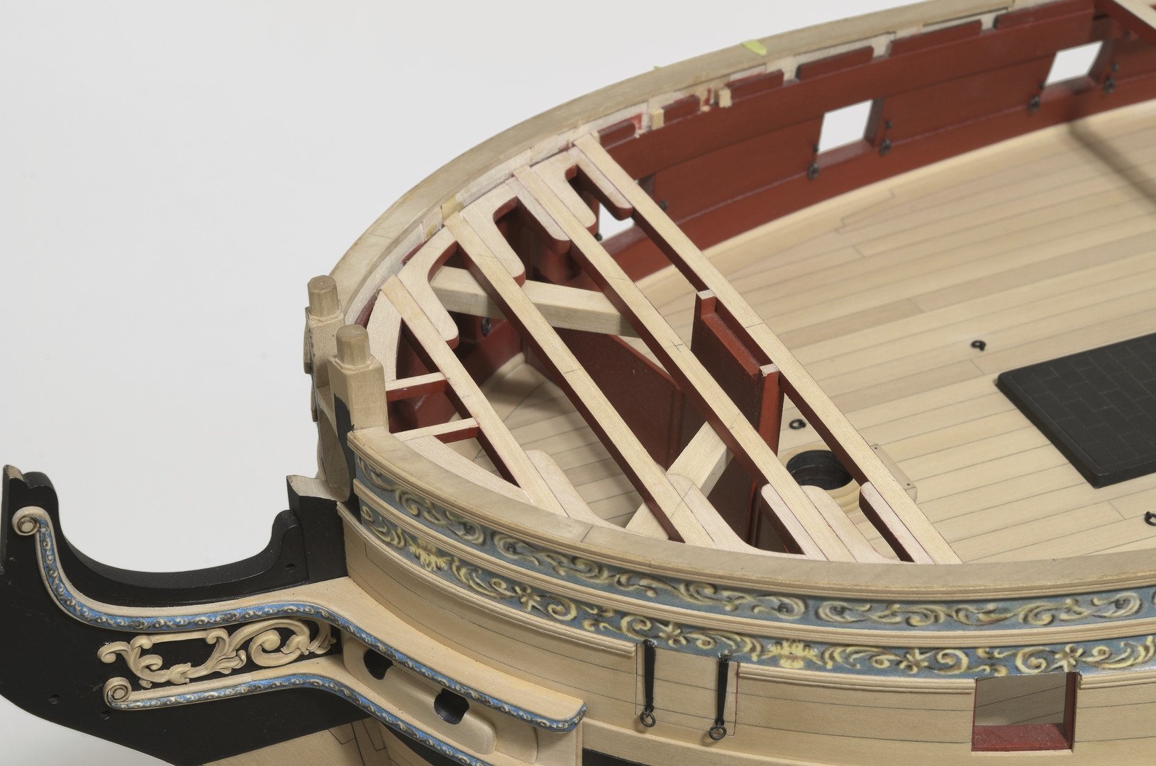
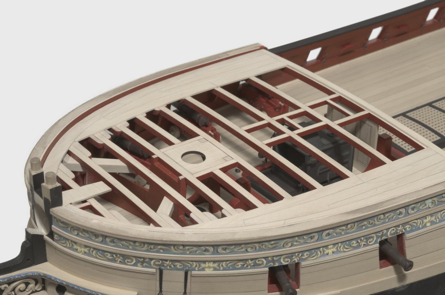
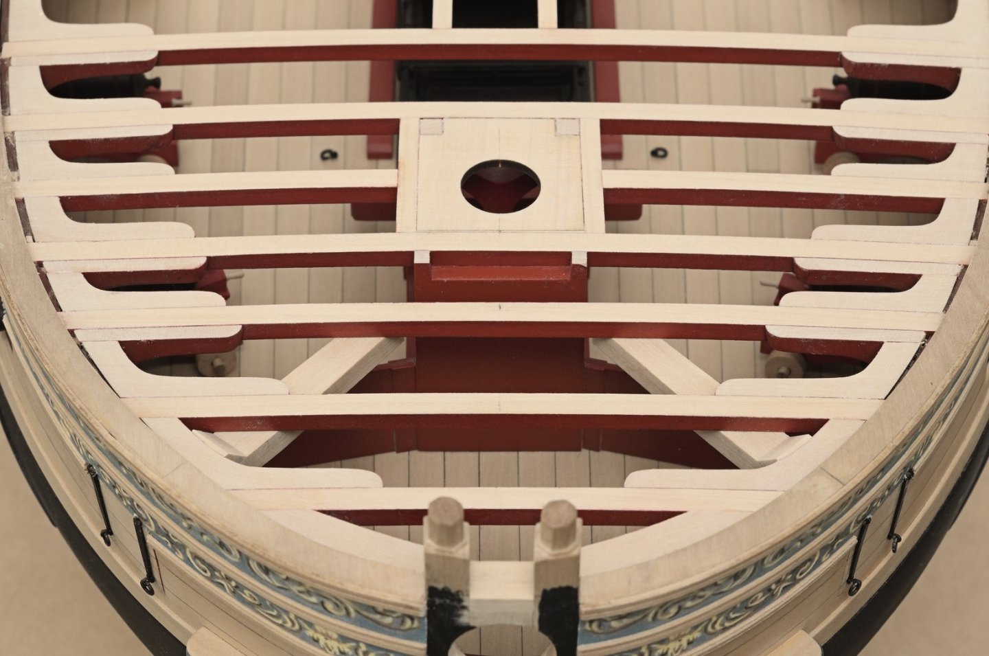
Chain pumps. . . I decided to make the 4 Rhodings from 1/16" x 1/64" brass strip. The square portion of the crank handle is only 3mm in length. Any longer and I think they would look out of scale. After blackening the brass rod I used some weathering powder to age the look of the metal. After that I added the the decorative moulding to the forward edge of the breast beam. Then came the elm pumps and QD bulwark planking. For the carlings I made simple wood templates that fit between the beams in order to position the carlings equidistant from the center of the deck. Mike

- 607 replies
-
- 21
-
-
- winchelsea
- Syren Ship Model Company
- (and 1 more)
-
Really nice work there! Love the colors too. So, what's next? Mike
- 70 replies
-
- 3
-
-
- Lowell Grand Banks Dory
- Finished
- (and 1 more)