HOLIDAY DONATION DRIVE - SUPPORT MSW - DO YOUR PART TO KEEP THIS GREAT FORUM GOING! (Only 27 donations so far out of 49,000 members - C'mon guys!)
×


Stuntflyer
-
Posts
1,197 -
Joined
-
Last visited
Content Type
Profiles
Forums
Gallery
Events
Everything posted by Stuntflyer
-
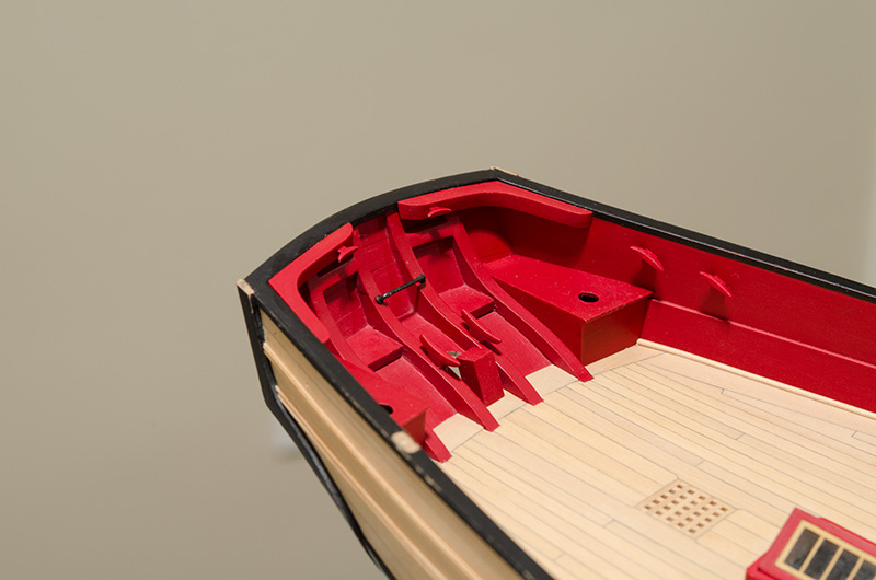
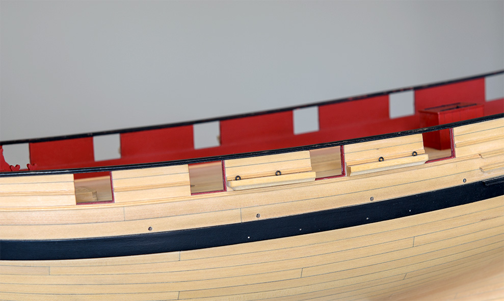
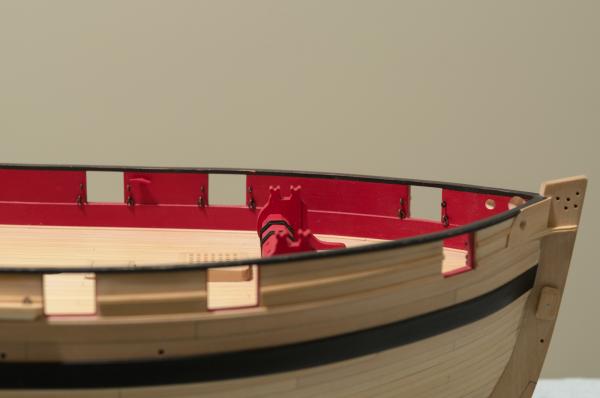
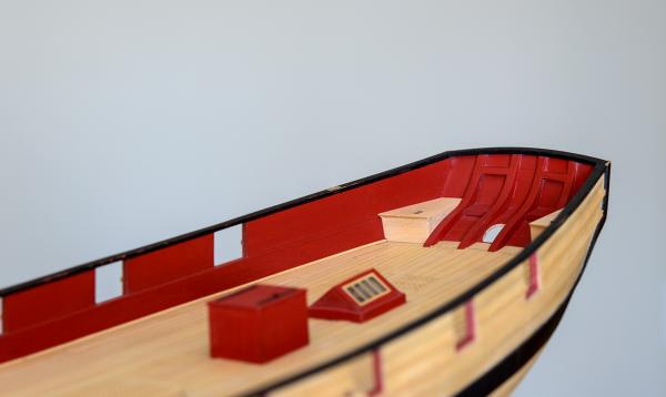
 I was able to complete the inboard stern details today. The knees with 5mm cleats, 9mm cleats on the stern frames, 22 gauge wire horse, false stern post and seats were added. There are tiny washers at the base of the horse made from 28 gauge wire. After forming them they were flattened with a plier. The outside diameter is only .065 so they are quite small. Being very hard to handle a few did end up as a permanent fixture in the carpet.
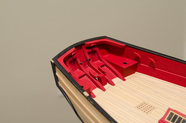
- 452 replies
-
- 19
-

-
- cheerful
- Syren Ship Model Company
- (and 1 more)
-
druxey, Thank you so much for the kind words. Chuck, I read your post #667 on making the breech rope after I had installed all the ringbolts. Funny thing though, I never made the connection that I would need to take them out. Anyway, they are all removed with no damage to the hull or the ringbolts. Thanks for the tip, Mike
- 452 replies
-
- 5
-
-
- cheerful
- Syren Ship Model Company
- (and 1 more)
-
I was just advised by Chuck to pull those eyebolts with the rings from the bulwarks. Its easier to seize them to the ends of the breech line first and then insert them into the holes. Otherwise it will be impossible to seize the rope to it while its in the bulwarks. Update: Luckily, I was able to use my old monokote heating iron to heat an eyebolt and easily remove one. Only 27 more to go. Aaaargh!
- 452 replies
-
- 4
-
-
- cheerful
- Syren Ship Model Company
- (and 1 more)
-
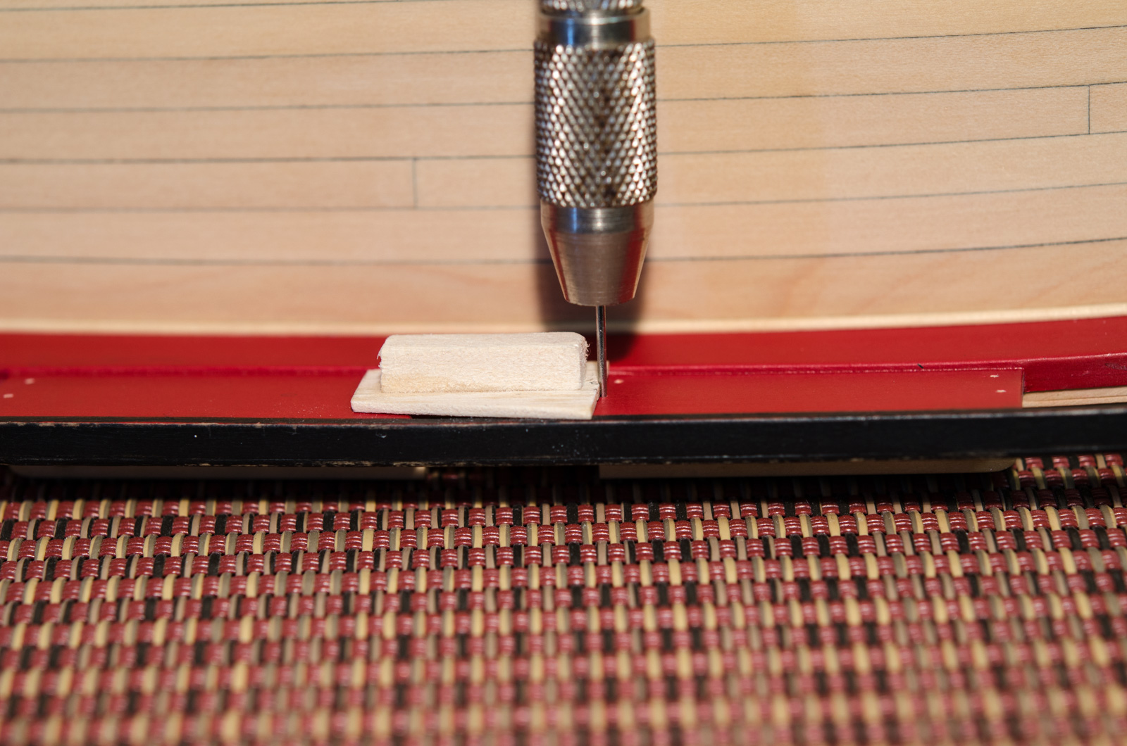
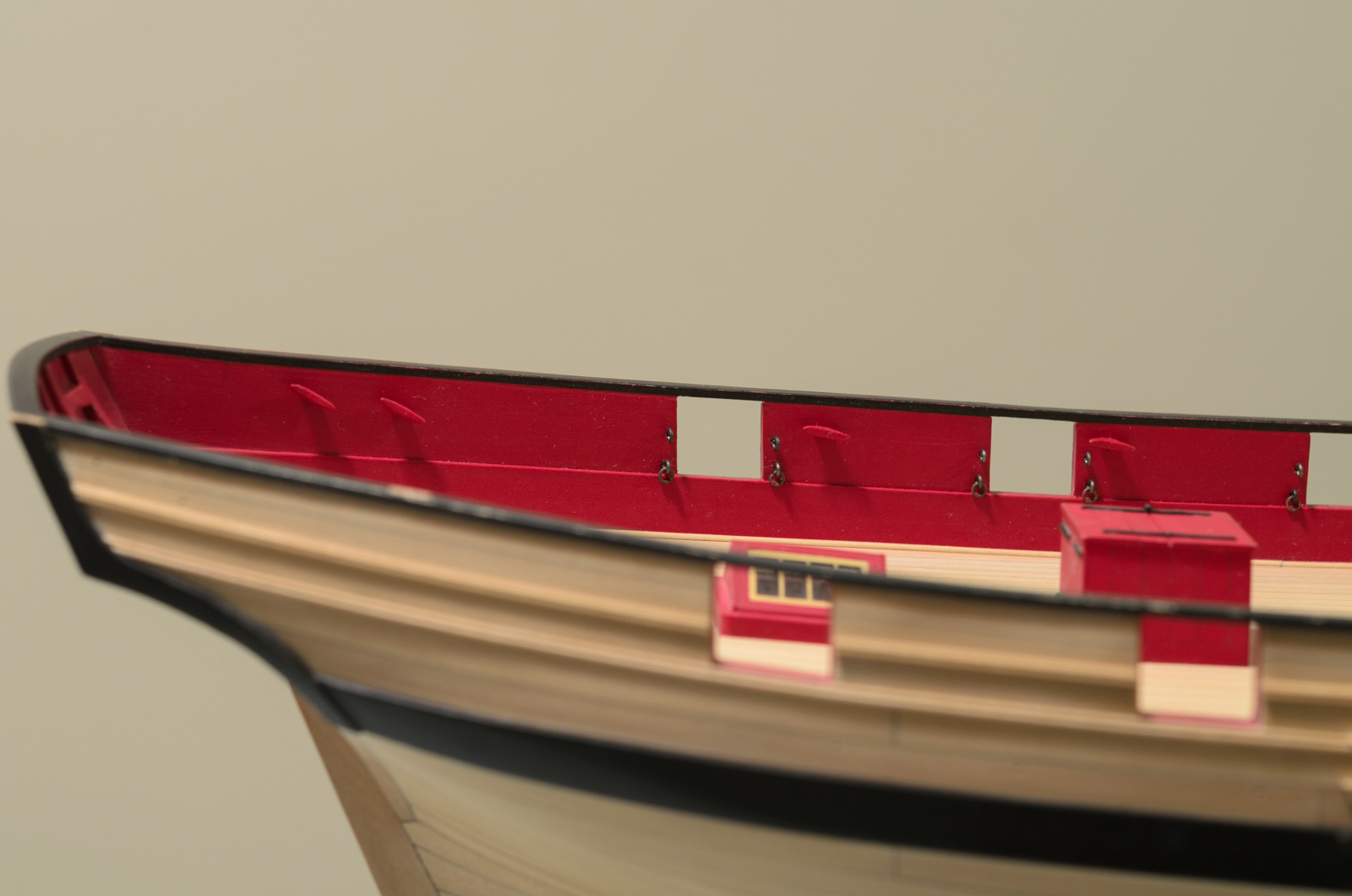
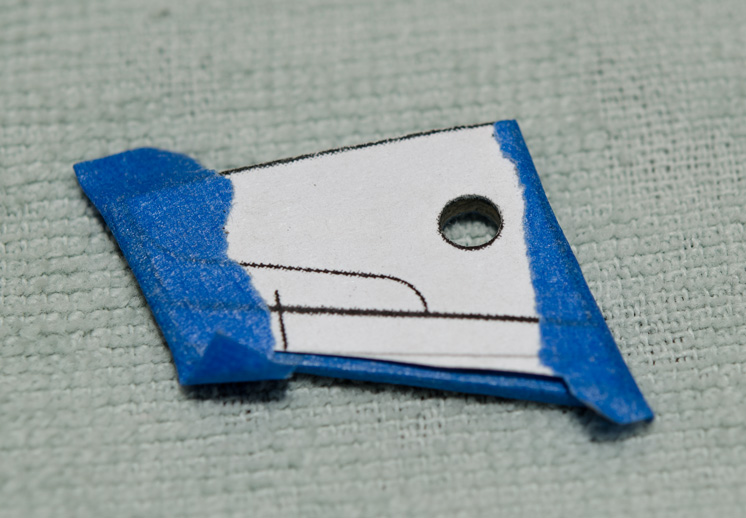
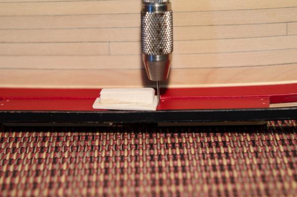
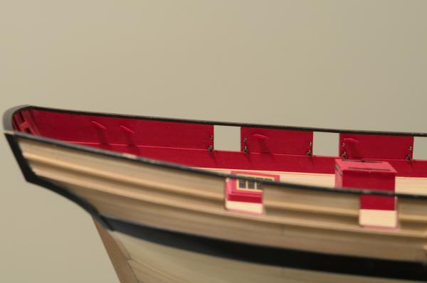
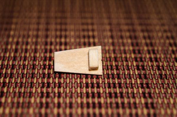
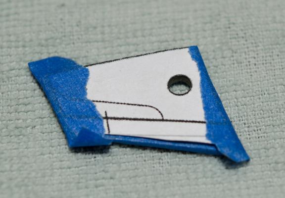
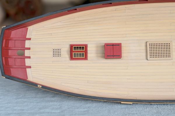
Today's post is the result of the last two weeks work. A little embarrassing perhaps since it seems that little was accomplished. Still, I'm pleased with the result so I really can't complain. The eyebolts and ringbolts were made from 24 gauge dark annealed wire. For consistent positioning I made a simple jig. The wedge shape allows the jig to angle so the ledge on the bottom can sit tight against the gunport. The small piece on top is a handle. I was a bit nervous about using CA here for fear of messing up the paint so I used slow drying epoxy. I placed a tiny bit onto a pin and worked it into the hole. The cleats along the bulwarks are all 7mm from Chuck. They were pinned and painted. Again, they were glued in with slow drying epoxy.
- 452 replies
-
- 15
-
-
- cheerful
- Syren Ship Model Company
- (and 1 more)
-
You're building one awesome looking ship, Druxey. Mike
- 641 replies
-
- 4
-
-
- greenwich hospital
- barge
- (and 1 more)
-
Jason, thanks! The longboat was a fun build. Any questions, please don't hesitate to ask. Enjoy! Mike
- 109 replies
-
- 3
-
-
- 18th century longboat
- model shipways
- (and 1 more)
-
I love your attention to detail and it shows in your work. At what point you finally say "good enough" is a choice only you can make. I think that your ability to "slow down" will result in a beautiful ship. Mike
-
Wonderful work as usual, Chuck. It's great to see where I will eventually be going. Mike
- 1,051 replies
-
- 5
-
-
- cheerful
- Syren Ship Model Company
- (and 1 more)
-
Movin right along, Rusty. Looks good to me! You could just tape it off and skip the freehand.
- 310 replies
-
- 2
-
-
- cheerful
- Syren Ship Model Company
- (and 1 more)
-
Looking very good! Had the same problem only I'm glad you were able to catch and fix the over faired area early on. Those pesky stern gun ports tested my patience as well. Mike
-
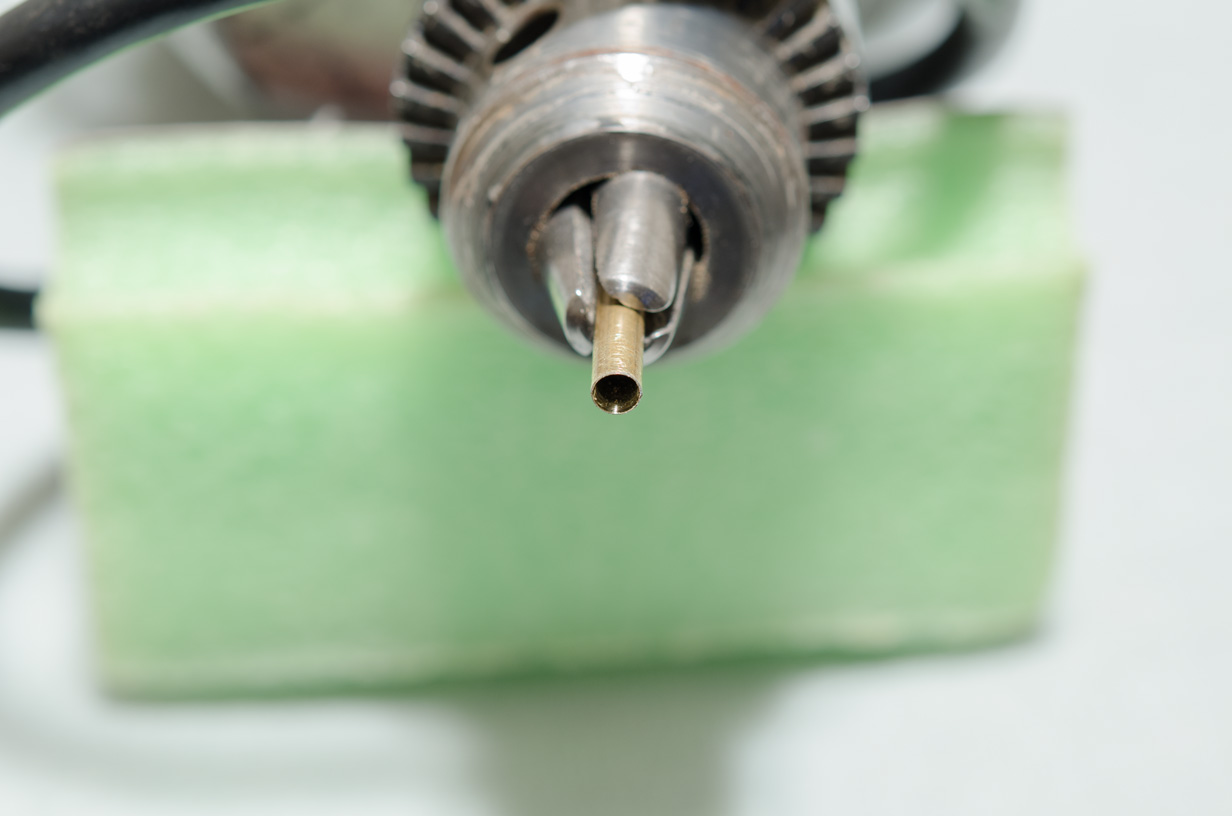
Over the past few days I managed to get the seats shaped and the channels installed. The holes for the seats were drilled using 5/32" O.D brass tubing. After placing the tubing in a hand drill, a #11 blade was used to taper and sharpen the inside of the tubing to a sharp edge. The tubing was placed in a drill press for drilling. Both sides of the seats were drilled at the same time for uniformity. Making them and fitting them was time consuming and a bit fiddly, but worth the effort. The seats will be spray painted off the ship along with the other inboard stern details. . I'm going to notch the channels after double checking the angle of the chain plates in relationship to the hole markings in the wales. The eyebolts were formed from black 22ga. wire. To avoid having to use oversize holes in the channels the eyebolts were made by a simple shaping of the wire. A tiny notch was filed into the channel to allow the eyebolt to sink in a bit. Since the wire was not twisted, I used 3 hour Epoxy to glue them in.

- 452 replies
-
- 17
-
-
- cheerful
- Syren Ship Model Company
- (and 1 more)
-
I wish I had thought of this when I was at this stage, Rusty. Mike
- 310 replies
-
- 2
-
-
- cheerful
- Syren Ship Model Company
- (and 1 more)
-
Thanks guys! It feels good to be able to work on the ship without all the saw dust. druxey, I don't think that pinning the windlass is needed here. Mike
- 452 replies
-
- 2
-
-
- cheerful
- Syren Ship Model Company
- (and 1 more)
-
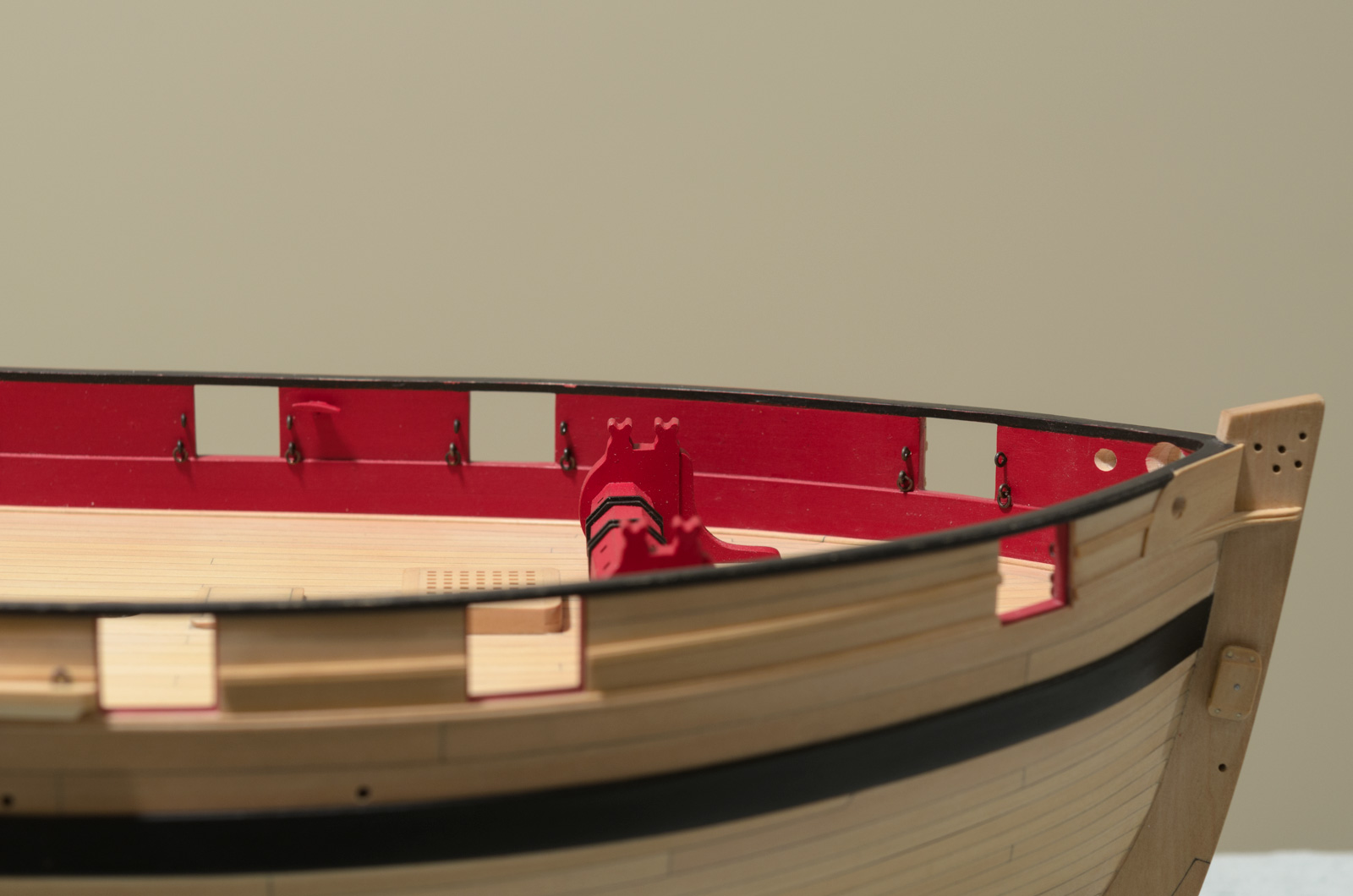
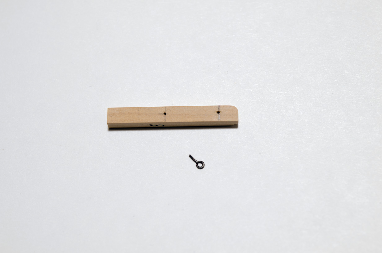
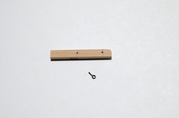
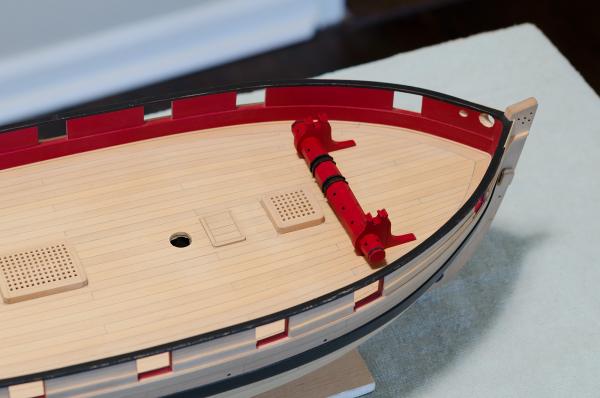
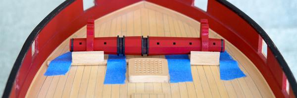
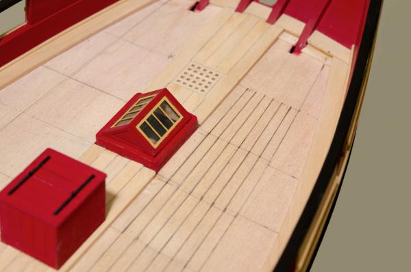
Just a small update. . After applying a coat of W-O-P to the deck I decided that it was a good time to attach the windlass. The most important thing was to get the windlass centered and parallel to the other deck structures like the coaming directly behind it. Varying plank widths at the bow meant that I couldn't use those joints as an additional guide for alignment. With this in mind and not trusting my eye, I decided to make a jig. The jig was made from a stick ripped to the width of the distance from the coaming to the back of the windlass. Vertical pieces were then glued to the stick for the windlass to back up to. After heat bending the jig was I taped it down to the deck against the forward edge of the coaming. Aligning the windlass was a simple matter of centering it and backing it up to the jig while holding it down for a few minutes until the glue set. Still need to clean up some of the dust remaining inside th ports.
- 452 replies
-
- 23
-
-
- cheerful
- Syren Ship Model Company
- (and 1 more)
-
Thanks guys! Your coments and "Likes" are very much appreciated. Now its back to sanding! Mike
- 452 replies
-
- 2
-
-
- cheerful
- Syren Ship Model Company
- (and 1 more)
-
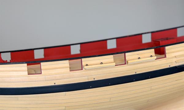
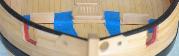
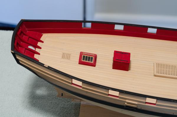
Hello Everyone, Normally I like to do a final sanding and a coat of W-O-P before posting. Today I'm just too excited as I have finally finished all the deck planking. Much of it was done with the aid of Dewalt Trigger Clamps. As space became tight I reverted to using wedges cut from 1/16" basswood or scrap boxwood sheet. The wedges allow for as much pressure as needed to close gaps. PVA was used throughout. The Bulwarks where masked of to prevent any damage to the red paint. As you can see in the photos, I have started sanding the starboard side. There is much more to do so I will spend the next day or two finishing up. Will post some photos once the W-O-P is applied. Yippee!
- 452 replies
-
- 23
-
-
- cheerful
- Syren Ship Model Company
- (and 1 more)
-
I like the tool you made for drawing the reference line.
- 310 replies
-
- 3
-
-
- cheerful
- Syren Ship Model Company
- (and 1 more)
-
Cutter Cheerful 1806 by rafine - FINISHED
Stuntflyer replied to rafine's topic in - Build logs for subjects built 1801 - 1850
A milestone for sure, Bob. It really does look great with all the deck fittings in place. Looking forward to your posts on rigging.- 525 replies
-
- 5
-
-
- cheerful
- Syren Ship Model Company
- (and 1 more)
-
Great start Deon, I will be following. . . Mike
-
Great to see you building again Rusty. I've had a great time building Cheerful and I'm sure that you will too. Please keep those photos coming. Mike
- 310 replies
-
- 4
-
-
- cheerful
- Syren Ship Model Company
- (and 1 more)
-
This is definately a first for me Druxey. I have never had the pleasure of following any of your build logs. Let's just say that I'm very excited to see this one. Mike
- 641 replies
-
- 4
-
-
- greenwich hospital
- barge
- (and 1 more)
-
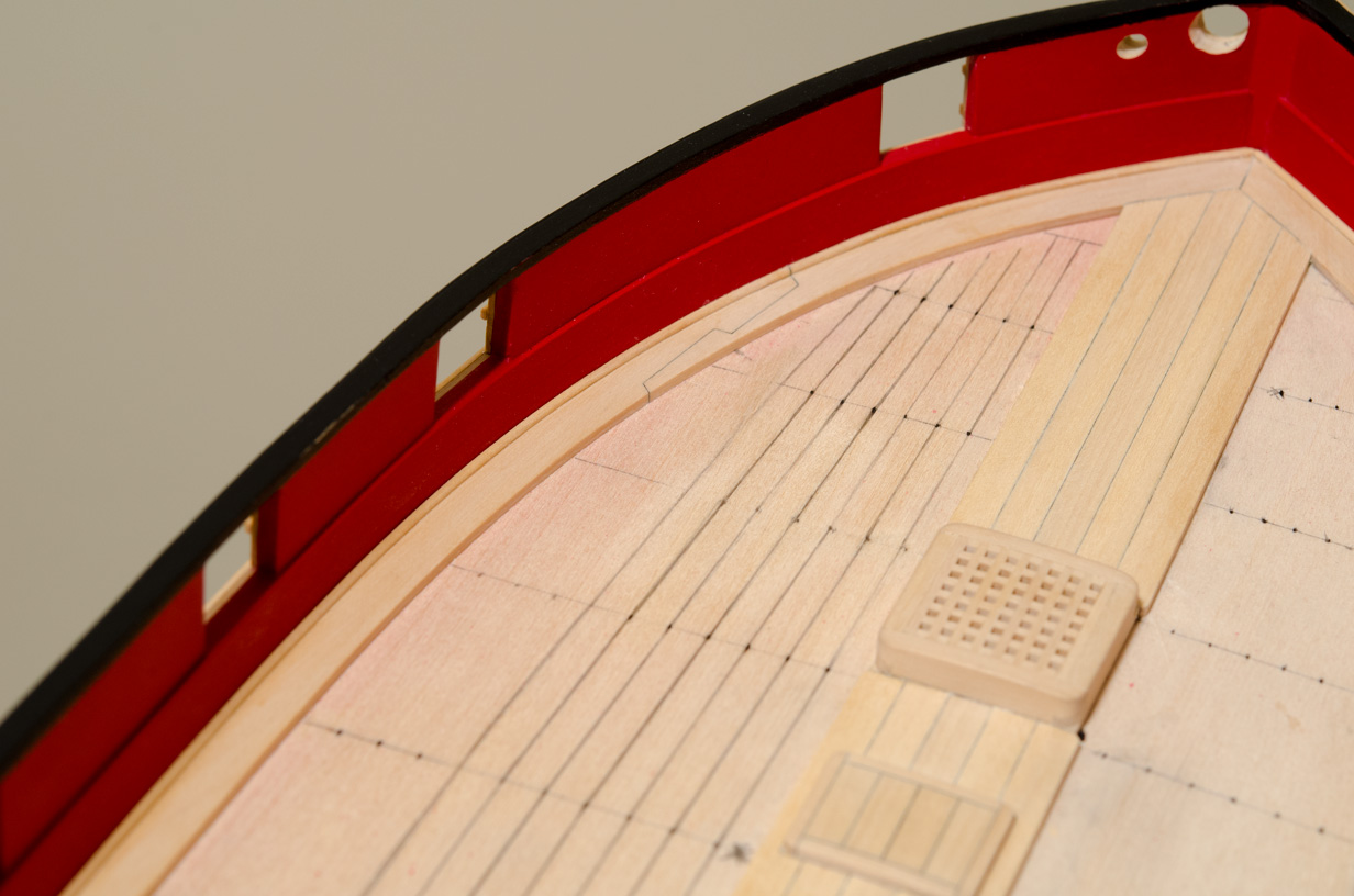
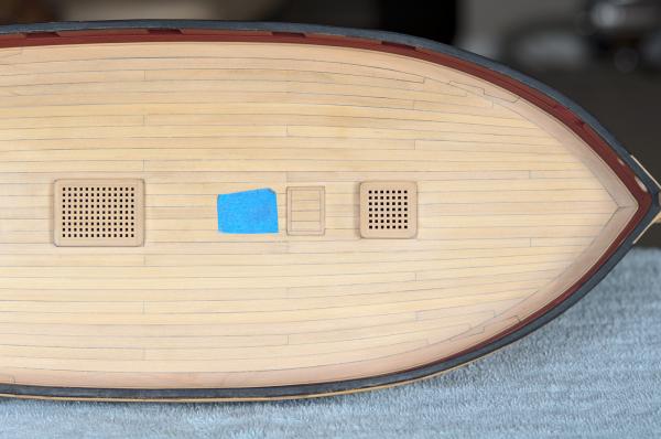
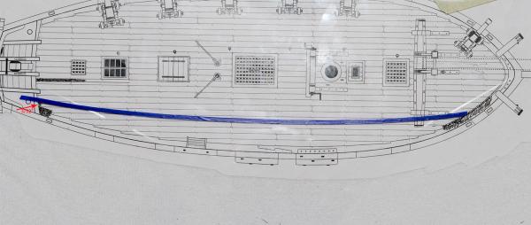
I started lining off the deck today. . . Using a tick strip, the deck beam reference line on the fore side of the main hatch was divided into equal segments. Mine needed eleven, each segment being slightly under 3/16". I divided the eleven spaces into two belts seven inner and four outer. To establish the two belts down the length of the hull I decided to get the initial curve from the plan and adjust it later if needed on the deck itself. I had already made a copy of the plan sheet showing the deck. I made a few changes to the plan to correspond to the actual build. I placed a thin sheet of glass over the plan and used a ships curve and a fine line marking pen to draw the curve. Once I was satisfied with the run of the curve I placed 1/8" tape along the line directly to the glass. A photo was taken and printed so the curve could be glued to card stock. Placing the curve on the deck showed that only a slight adjustment was needed at the location of the tick mark which divides the two belts. With the curve redrawn and a line transferred to both sides of the deck, I was ready to complete the remaining tick marks. Connecting the tick marks really helps to see what the run of planks will look like. In a few places I included the planks tab into the measurments and that was enough to throw off the even flow of planks down the hull. If I had not connected the tick marks it would have been very difficult to spot these errors. Mike

- 452 replies
-
- 20
-
-
- cheerful
- Syren Ship Model Company
- (and 1 more)
-
Looks really good! Mike