Stuntflyer
-
Posts
1,197 -
Joined
-
Last visited
Content Type
Profiles
Forums
Gallery
Events
Everything posted by Stuntflyer
-
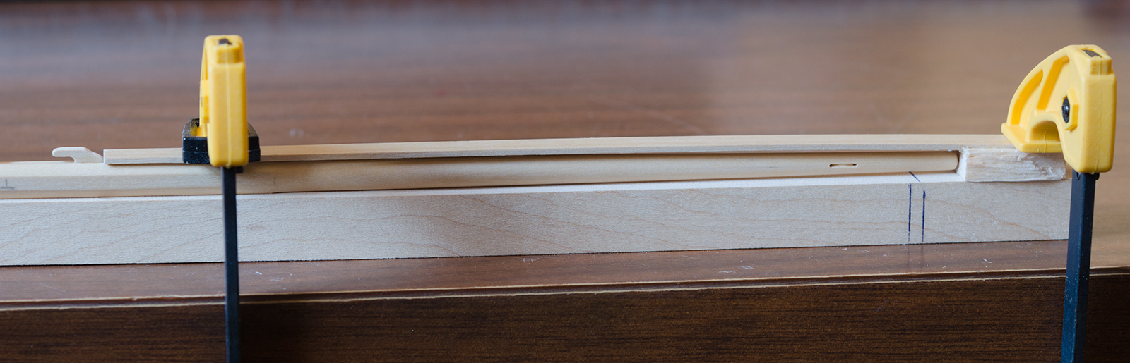
 One of the things I really need to do is to raise the height of my work table to around 44". Sitting while bending over creates too many back issues for me. Once that's done, hopefully later this week, I will start on the bobstay rigging and tackle. Meanwhile I did manage to finish up most of the mast work. Cheeks where made as described in TFFM Vol. 4 pg. 16 Scrap boxwood was glued to a dowel for shaping
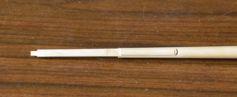


- 452 replies
-
- 22
-

-
- cheerful
- Syren Ship Model Company
- (and 1 more)
-
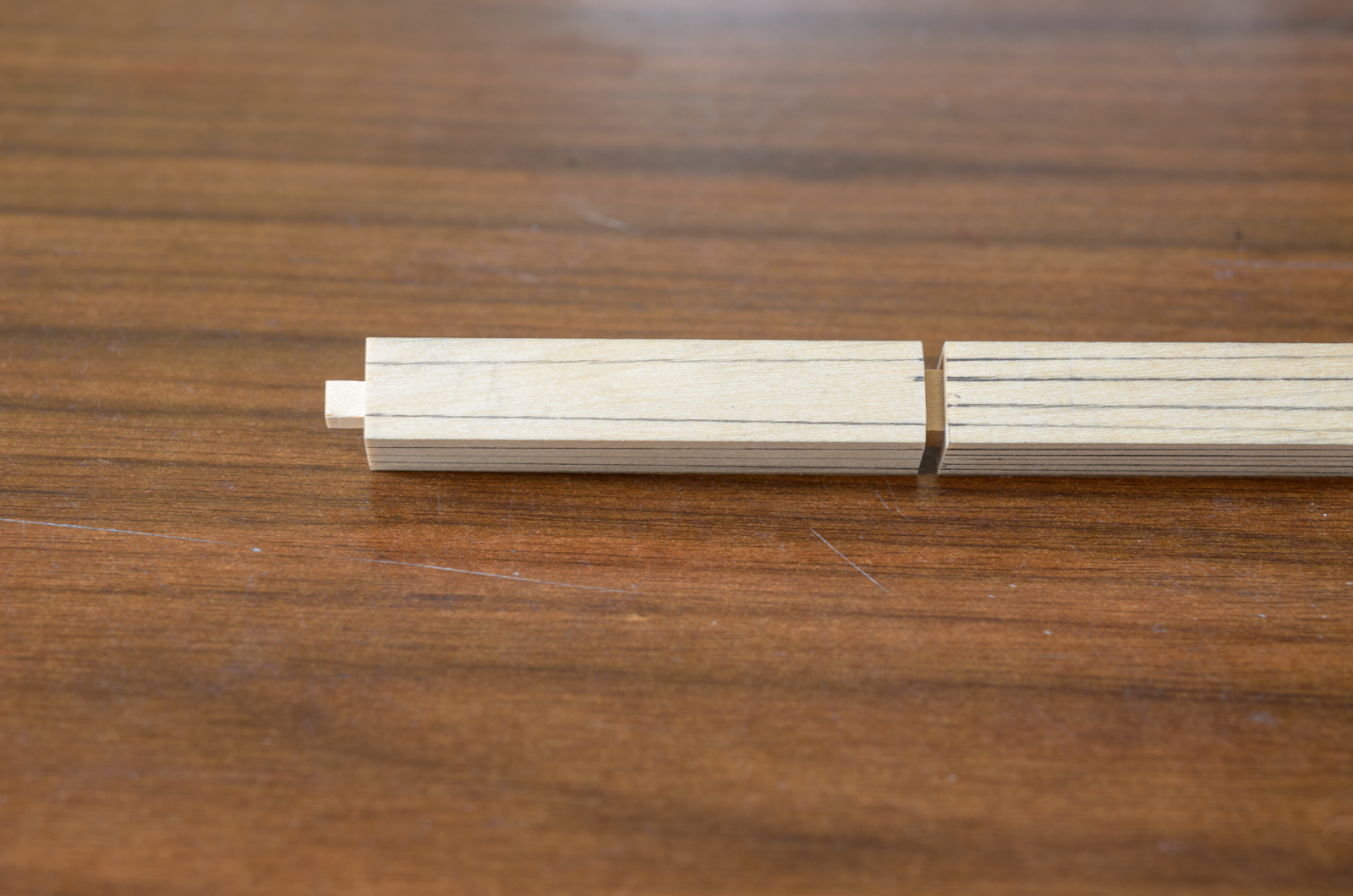
Ken, The mast stick was longer than needed. After cutting the mast to the proper length, I used the off cut from that stick to measure for the proper depth of the square section. Mike
- 452 replies
-
- 4
-
-
- cheerful
- Syren Ship Model Company
- (and 1 more)
-
So sorry for your loss, Erik. Looking forward to your future posts. Mike
-
Thank you Nils, Bob, Steve and for all the "Likes". . Steve, I definitely think that the Model Shipways Mayflower kit is worth considering as a first ship build. You might want to pick one up at the end of the year when a number of their kits are sold at highly reduced prices. The main reason I stopped the build was due to some wood issues I was having. I purchased boxwood from a supplier who, for some unknown reason, had great difficulty cutting a straight piece of strip wood. Each piece had to be painstakingly sanded before it could be used and my fingers were raw from doing so. There was so much waste, 30-40% perhaps, that I no longer have enough wood to finish the build properly. The wood I'm now getting from Jason over at Crown Timberyard is superior in every way but color wise would never match what I was using before. Never say never but as of now it's off the table. Mike
- 452 replies
-
- 5
-
-
- cheerful
- Syren Ship Model Company
- (and 1 more)
-
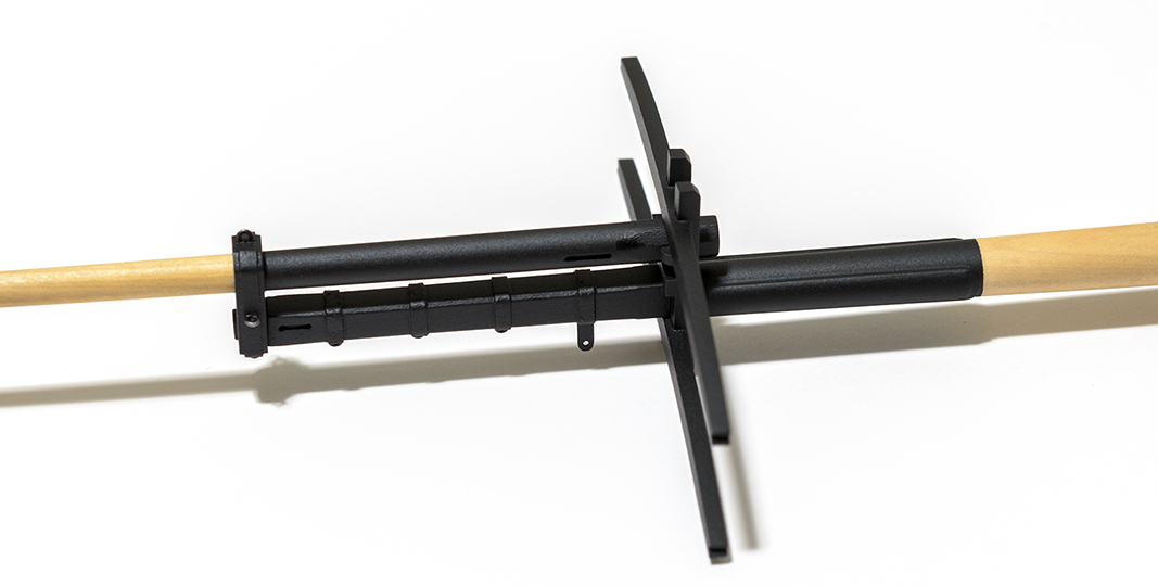
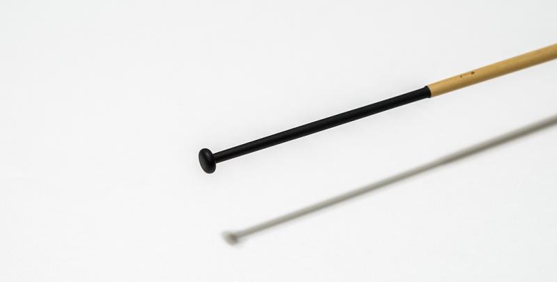
I've been working on the boom, gaff and yards lately. All of these were made from square sticks. I made a simple jig to make sure that the spacing of the cleats were the same from the ends of each yard. These will eventually be painted black. .

- 452 replies
-
- 19
-
-
- cheerful
- Syren Ship Model Company
- (and 1 more)
-
Very nice work Aviaamator! I wish my grandson were a bit older. I could use a helping hand. Mike
-
Thank you so much for the kind words and "Likes". I still need to add the mast hoops, cheeks, etc; before I can complete the mast assembly and its painting. Hopefully this will all get done within the next few weeks. I'm anxious to see it in a completed state.
- 452 replies
-
- 6
-
-
- cheerful
- Syren Ship Model Company
- (and 1 more)
-
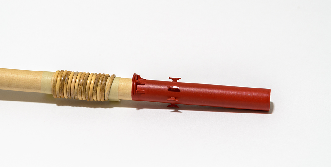
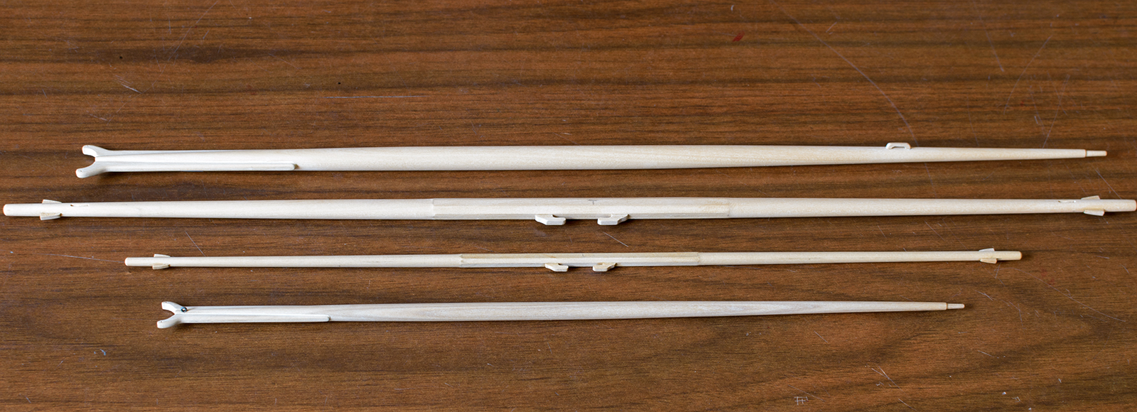
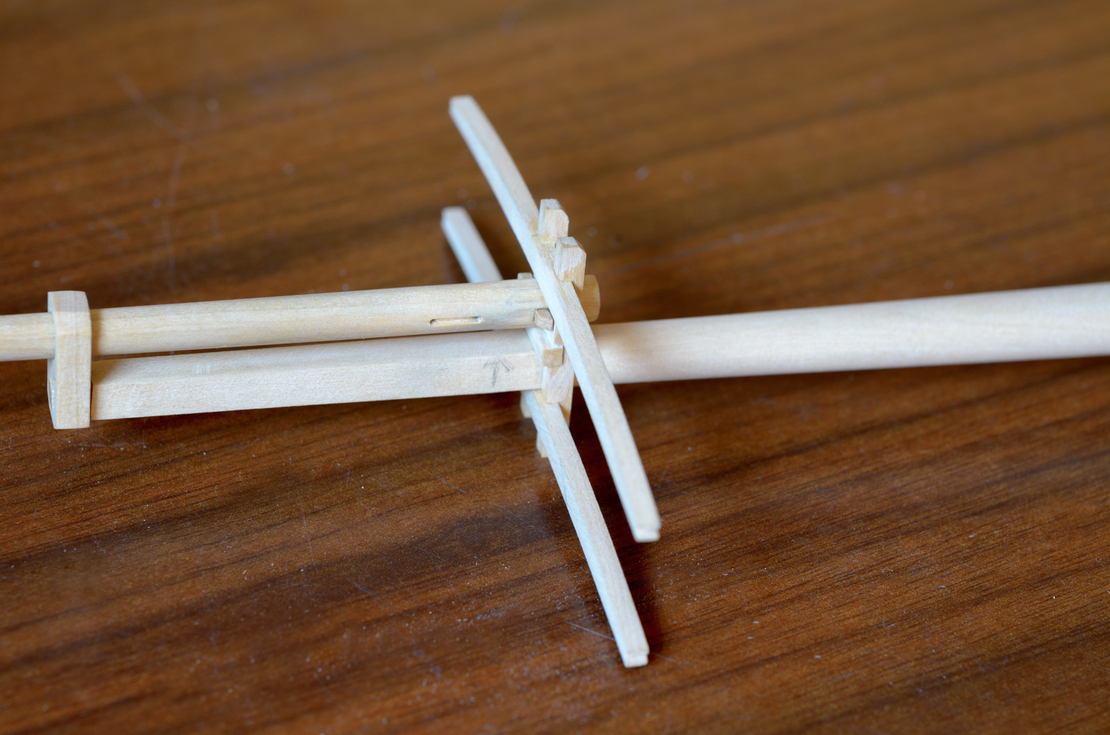
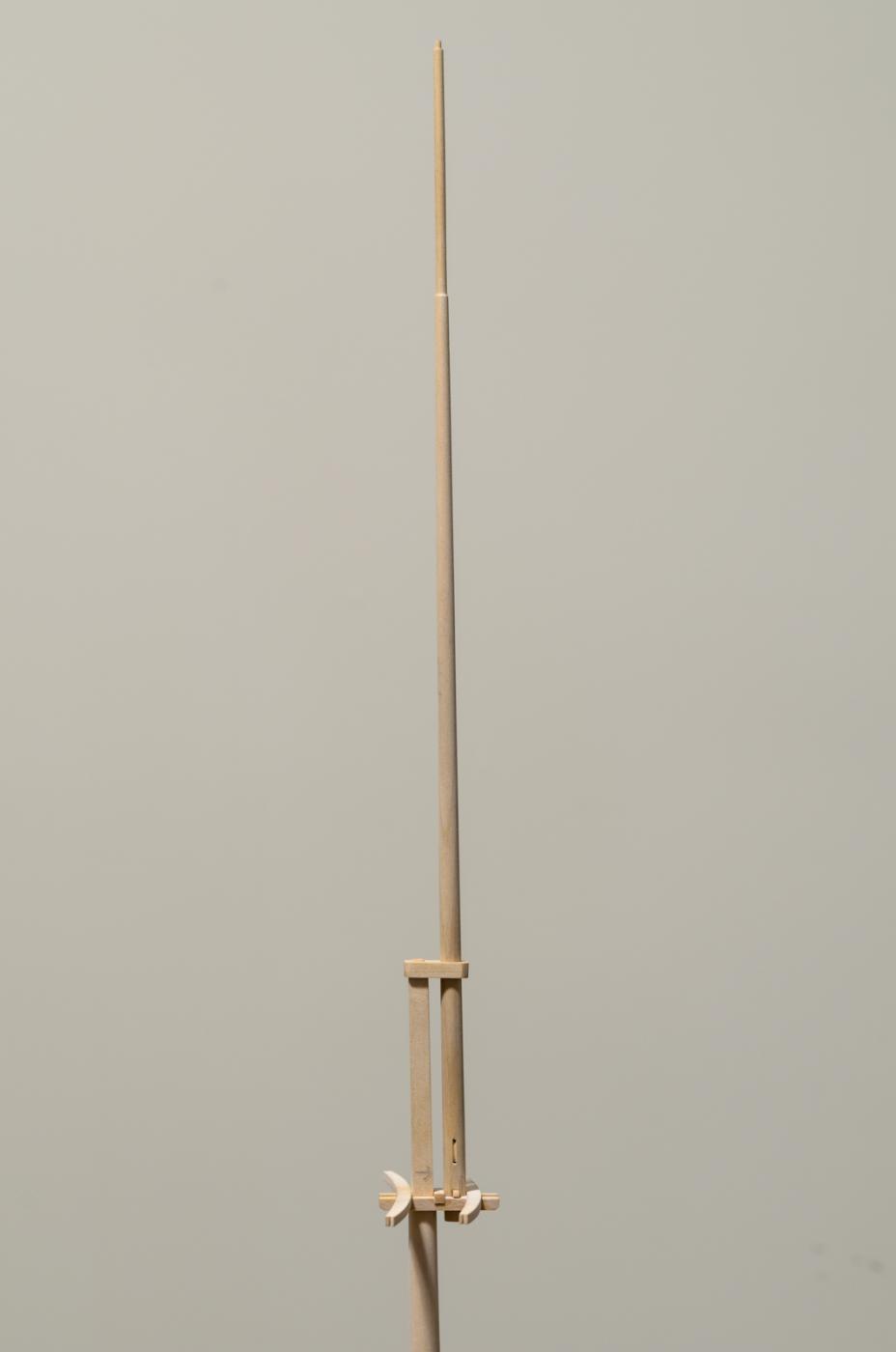
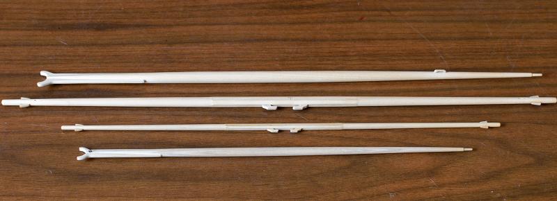
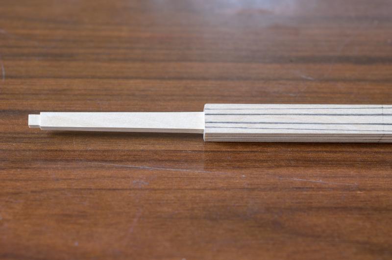
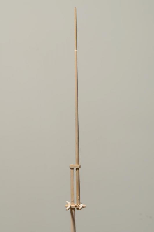
I've been working on the mast assembly over the last few weeks including the trestletrees and crosstrees. Making the lower mast was straight forward with the exception of its square section at the top. I thought it best to try and delineate and complete the square section first before doing any rounding of the lower section. I made the saw cuts being careful not to cut too deep. I used an off cut to establish the proper depth for each cut. Once that was done, I filed between the two cuts to flatten the area just enough to allow the trees to fit nicely over the mast. The trees sit at a slight angle which was accounted for when filing this section. A tenon was later added for the mast cap. The lower section of the upper mast was then rounded off using the same method as described for the bowsprit. The upper mast was then completed. Again care was taken to get a nice fit when the octagon shape at the lower section of this mast is inserted into the trees. There is also a 1/16" strip preventing the mast from falling through the trees. A few more photos showing the boom rest, a few cleats and the upper mast.


- 452 replies
-
- 28
-
-
- cheerful
- Syren Ship Model Company
- (and 1 more)
-
Nicely done, Thomas! One thing I'm not clear on is how you fabricated the chimney foot. If not too much trouble, could you detail that a bit more? Mike
-
Thanks, Erik! The great work of yours and others has inspired me to do better. One of the things Chuck said that stood out in my mind was about how slowly he works and I know it's something that you do too? I started doing this in the last year and I'm glad I did. It seems like every time I start to speed things up the results end up being disappointing. Mike
- 452 replies
-
- 4
-
-
- cheerful
- Syren Ship Model Company
- (and 1 more)
-
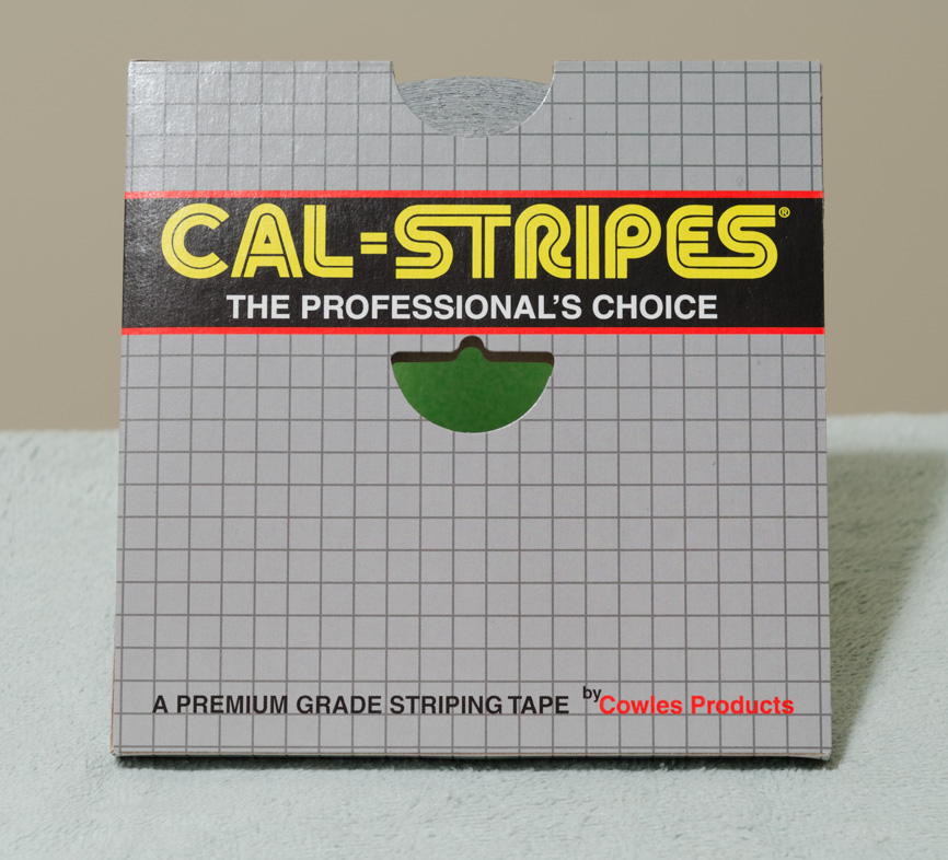
Thank you, druxey! Spreading it out over a four day period made it easier to digest. Oh, I almost forgot. . I used the same striping tape here as I did on the rudder. It was cut to a width of 3/32". The eyebolts are made from 24 gauge black annealed wire. I still need to darken the inside of the sheave and Poly the bowsprit.

- 452 replies
-
- 25
-
-
- cheerful
- Syren Ship Model Company
- (and 1 more)
-
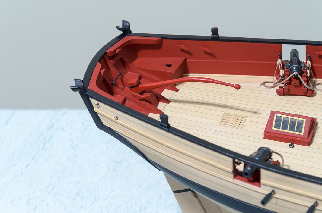
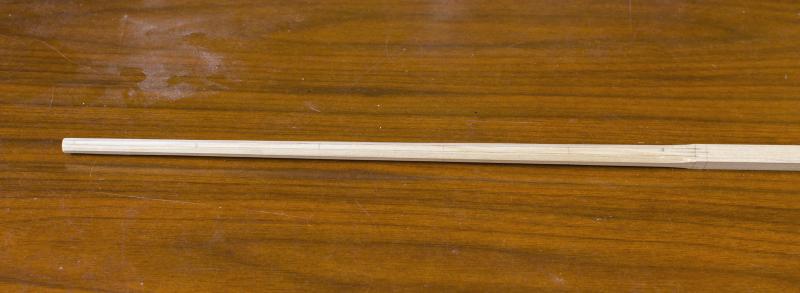
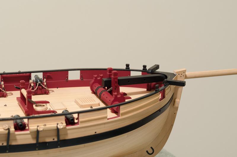
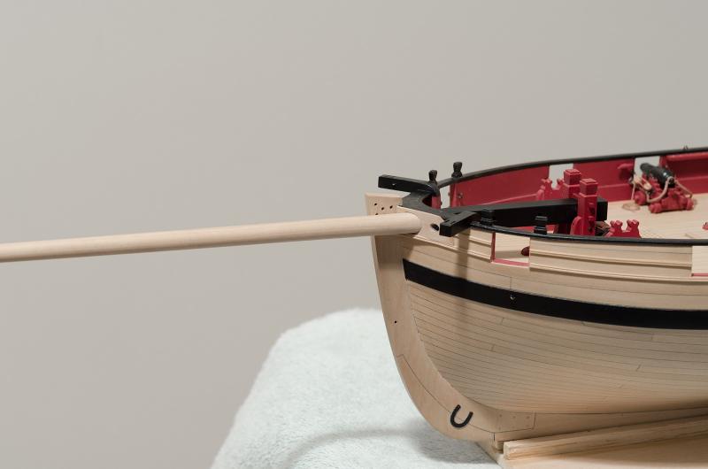
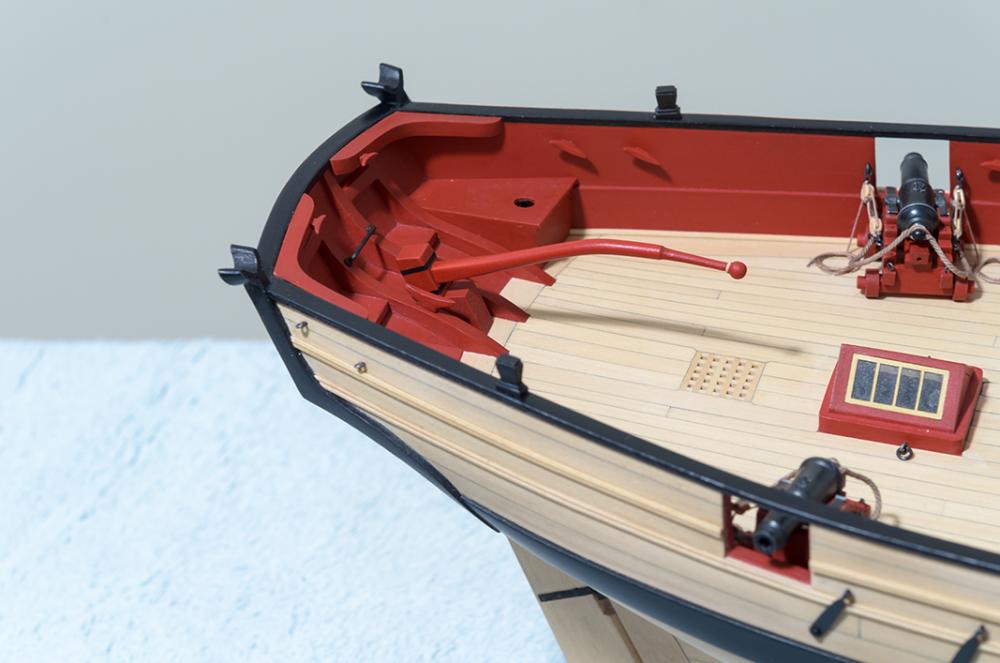
The making and fitting of the bowsprit proved to be a very interesting project along with a few challenges along the way. . The square stick was marked off on opposite sides every two inches for the length of the bowsprit. Using the plan as a guide a 7-10-7 tapered template was used to mark the bowsprit width at each of the 2 inch locations. Then a ships curve was used to join these marks along the entire length of the bowsprit. The disc sander was used to remove the wood outside the tapered line. The process was repeated on the two remaining sides. Using my hobby vise, which now has removable rubber jaws, the bowsprit was filed down to achieve the octagon shape. Care was taken not to file past the lines while keeping the surfaces as flat as possible. The bowsprit was rounded off, a task easily accomplished using the "shoe shine" technique with sandpaper. So far so good, I thought. . Fitting the bowsprit into the hull proved to be a very time consuming process. The bowsprit has to be slid over the deck fittings at a downward angle. Once clear it can be lowered into the bowsprit bit. Problem was, the bowsprit was rubbing on the bottom of the pin rail at the bow making it difficult to move it forward. I had no choice other than to remove the pin rail. Once the hole was completed, the end of the bowsprit could be lowered into the bit. The hole shape was close though there was a bit too much slop where it exited the hawse plate. This was unacceptable, so I removed the plate and made a new one after the bowsprit was affixed to the bit. This proved to be another challenging task as the plate becomes very fragile as the hole is enlarged. I fixed the hole fit inside the hull with some filler and paint. I added a new pin rail from thinner 1/32" sheet which now sits flush with the cap rail. It goes to show that there must be some measurement which was slightly off thus making it difficult to do what would seem to be a straight forward task. Anyway, I'm happy with the result overall.

- 452 replies
-
- 20
-
-
- cheerful
- Syren Ship Model Company
- (and 1 more)
-
Beautiful job, Thomas! The additional work makes it unique. Mike
-
It's always good to have Druxey around helping to keep us on the right path. Mike
-
Thank you very much, again! Matt, I profiled my camera for indoor lighting yet color correction is still sometimes needed. I guess I should blame the camera. WYZWYK, Photos are great for covering up "slight imperfections". druxey, I bet that you have a shoe box full of those cartoons. Keep 'em coming. Mike
- 452 replies
-
- 4
-
-
- cheerful
- Syren Ship Model Company
- (and 1 more)
-
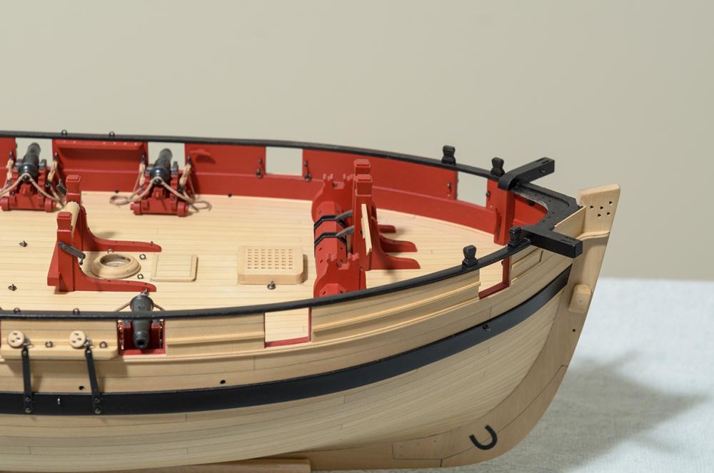
What's that old adage, "measure twice cut once". That's what I should have done while making the bowsprit. Luckily Jason over at Crown Timberyard had another stick to send me. That's my next project. Meanwhile the bowsprit step is now painted and in temporary position. I still need to weather the windlass gears, while being careful not to get any of the powder on the deck. Should be fun. Matt, if your looking in, This is closer to what the deck color really looks like.

- 452 replies
-
- 22
-
-
- cheerful
- Syren Ship Model Company
- (and 1 more)
-
Thanks guys! I've been recovering from some back issues, hence the late reply. Matt, I'm using Winsor & Newton "Crimson" red mixed with their "Burnt Umber" in a ratio of 10 to 1. For the black, I'm using Grumbacher "Mars Black". I started with the same color from W&N before switching to Grumbacher. For some unknown reason It goes on smoother and dries better than the same color from W&N. Looking at the photos I see why you would think that I'm using Holy for the deck. Nope, the deck is Boxwood with some Wipe-on-Poly applied. Mike
- 452 replies
-
- 3
-
-
- cheerful
- Syren Ship Model Company
- (and 1 more)
-
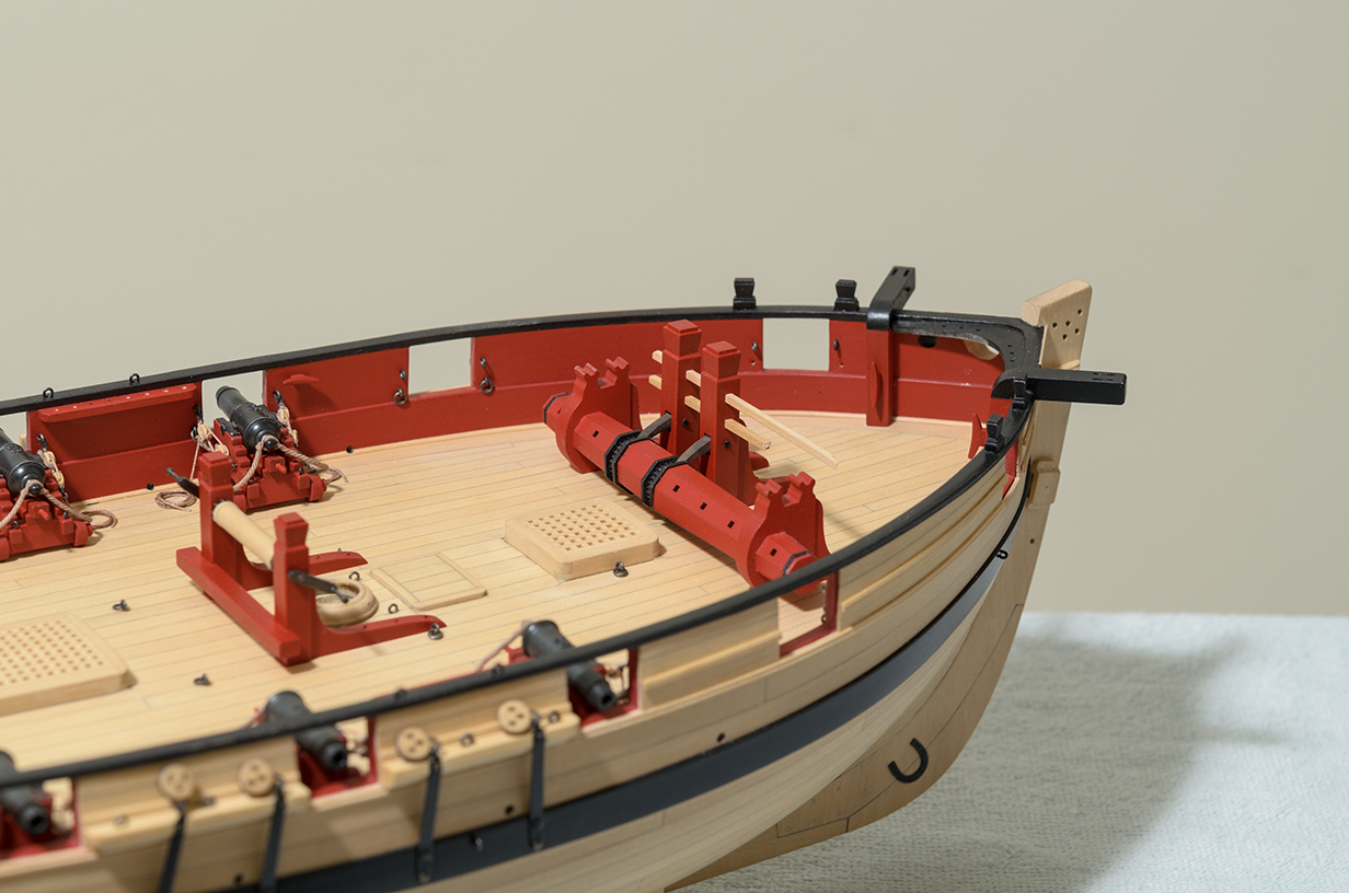
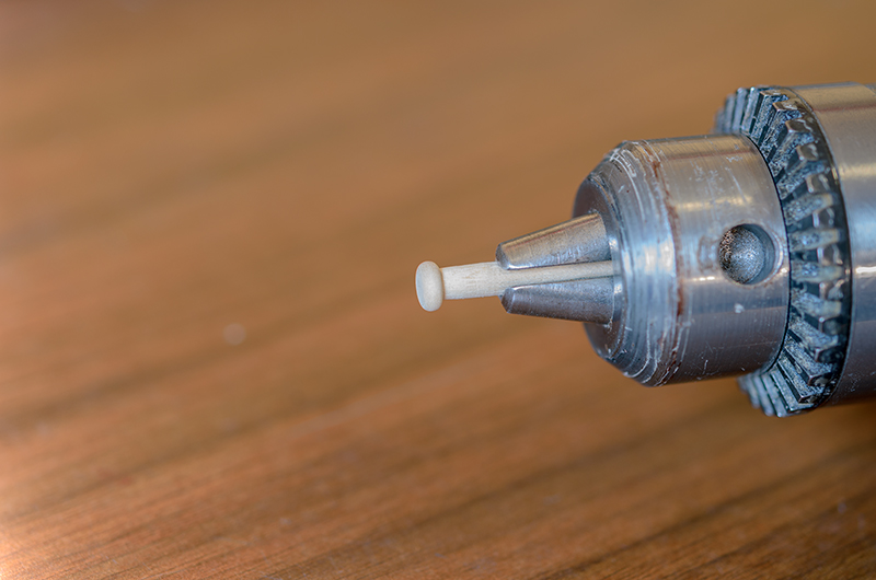
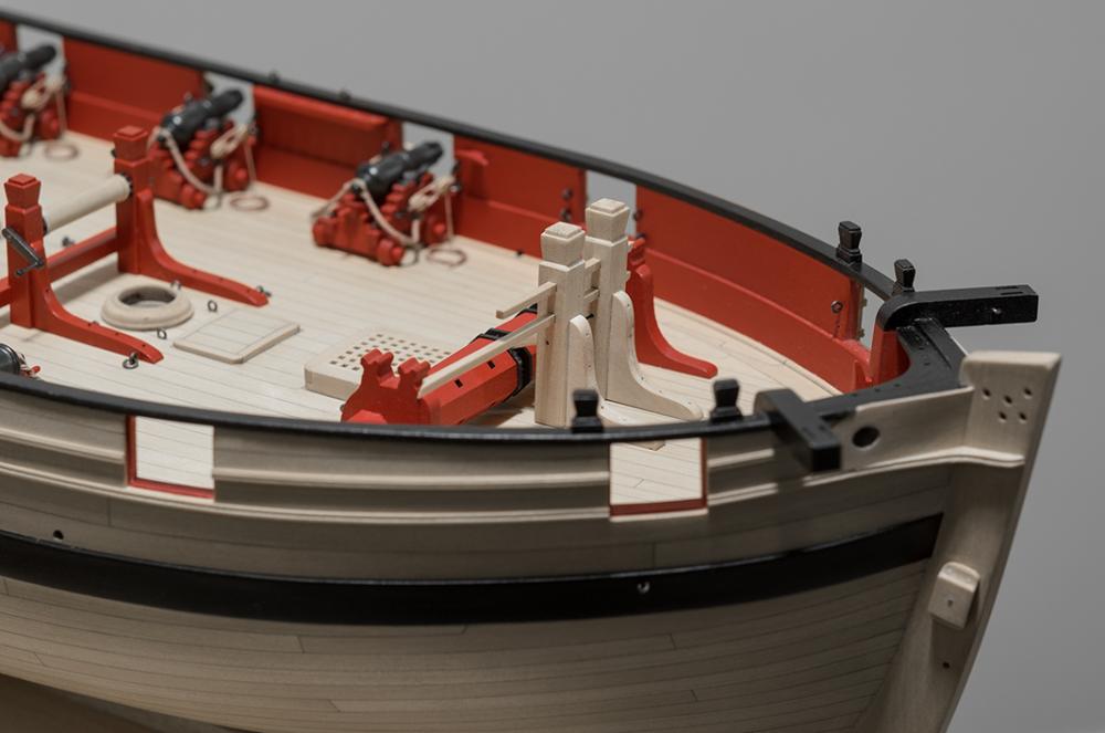
Hello everyone! Just a small update. The Quoin handles are now on the carriages. They are very small measuring 3/64" wide and 1/8" long. They were turned on the Dremel from 8mm boxwood belaying pins purchased from Model Shipways (also sold by Amati). The bowsprit step is scratched using Chuck's method as a guide. The only difference being that the beam holes in the middle post were drilled oversize 3/32", thus making it easier to file the square holes on the two outer posts. Some red paint, pins and washers will be added to complete the part.

- 452 replies
-
- 31
-
-
- cheerful
- Syren Ship Model Company
- (and 1 more)
-
Moving along. . . Still need to scratch the bowsprit step and then hopefully onto the bowsprit.
- 452 replies
-
- 24
-
-
- cheerful
- Syren Ship Model Company
- (and 1 more)
-
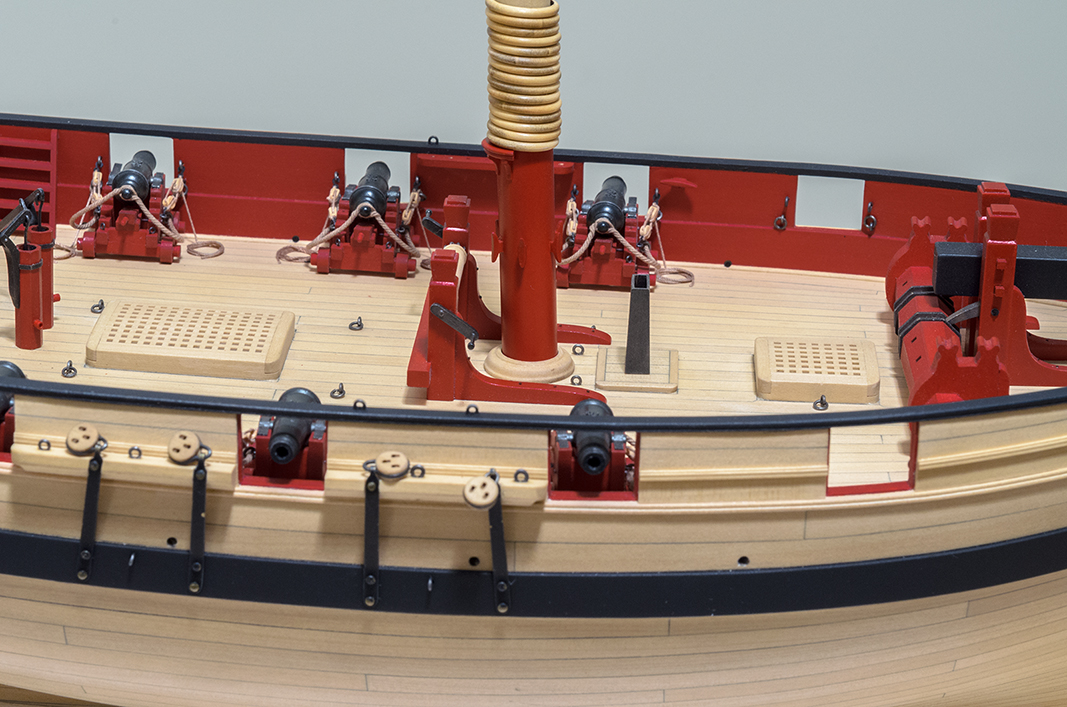
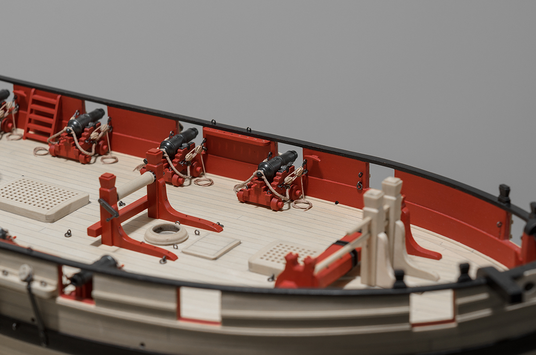
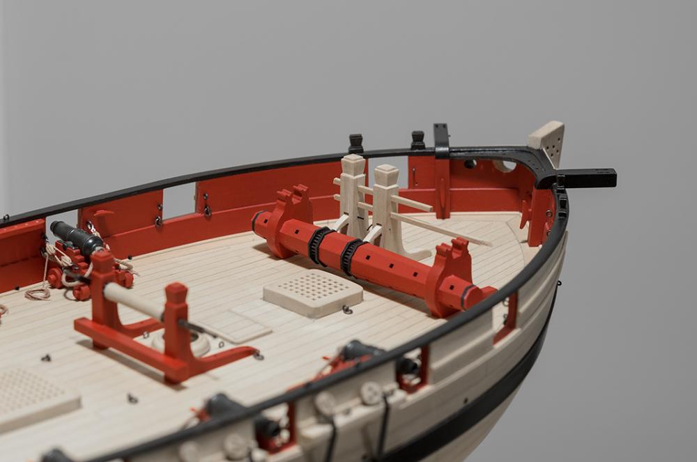
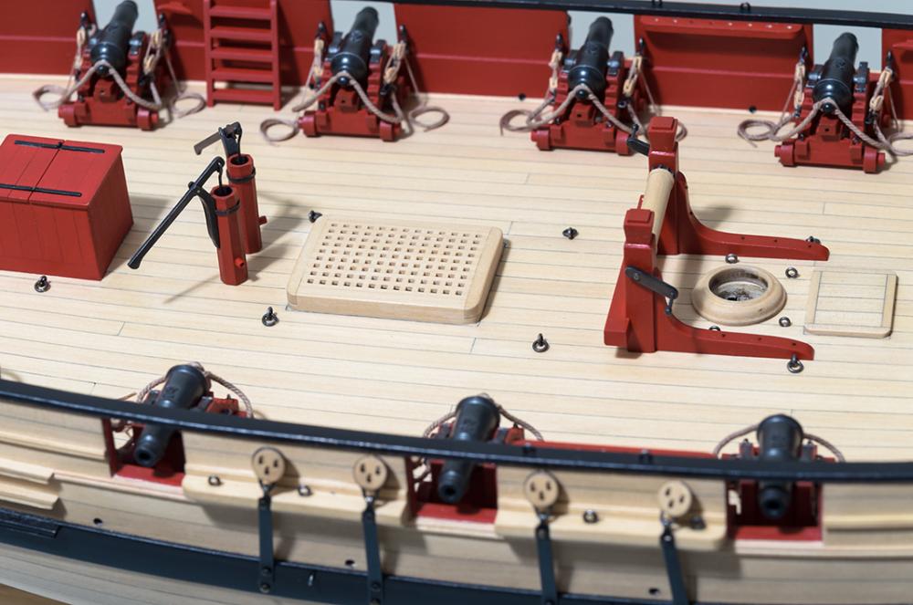
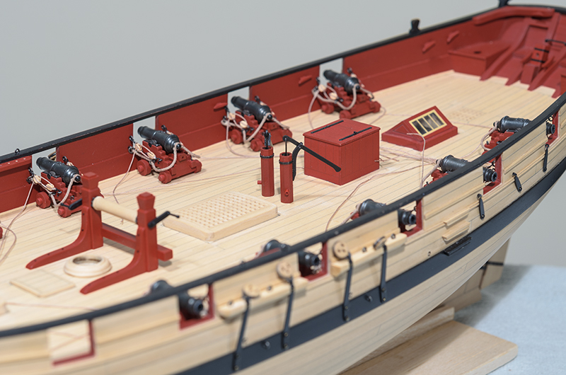
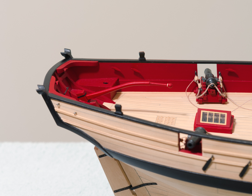
Got a few more tasks completed before I move onto completing the gun tackle. The pumps were made from Chuck's kit and the winch was scratch built. I had a blast while working on the winch. It consists of 12 separate pieces of wood. These parts are shown here in temporary position only and will be removed before I start to work on the gun tackle. I don't trust myself working in tight areas around somewhat fragile parts.
- 452 replies
-
- 22
-
-
- cheerful
- Syren Ship Model Company
- (and 1 more)
-
Coming along nicely, Brian I boxwood framed the forward chase ports too. I did it mainly to get a clean looking port instead of relying on having to shape the ply fillers. Either way, I think it would look fine since the port is thin enough to mask any minor shaping errors. Mike
-
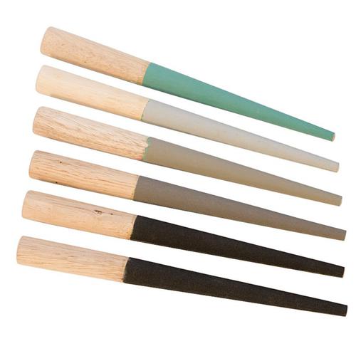
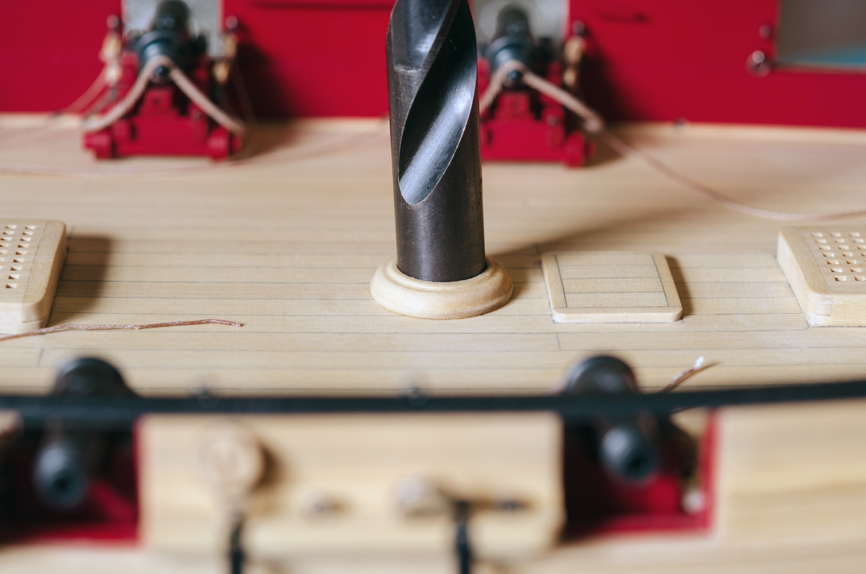
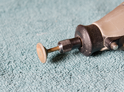
Thank you all for the comments and "Likes". To make the mast coat a boxwood disc was centered to the face of a Dremel sanding wheel with a drop of CA, spun at fast speed while filing in the shape. Afterwards, the part was soaked in acetone to release it from the wheel. The mast sits at a 4° angle, as near as I can measure. To allow the mast to tilt, I used a round emery sanding stick grit #2 inserted thru the bottom of the mast coat. Because the stick is tapered, I was able to remove material without damaging the top of the mast coat. http://www.esslinger.com/round-emery-sanding-sticks/ A 13/32" drill was used to check the angle.
- 452 replies
-
- 21
-
-
- cheerful
- Syren Ship Model Company
- (and 1 more)
-
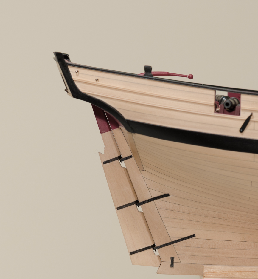
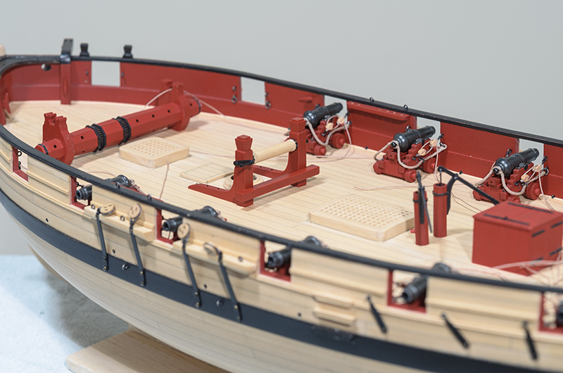
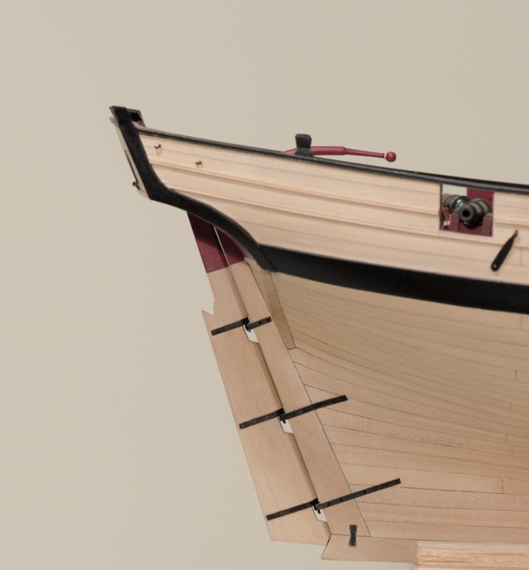
I guess I have been slackening off a bit lately, but I have somehow managed to work on a number of different Cheerful projects at the same time. Here is the first update. The carriages were rigged with the 3mm blocks. I still need to finish off the rope and do the coils. The rudder was scratch built. The straps were made from Chucks kit, using the thinner laser board and not the thicker wood straps. I used 24 gauge wire for the nails. After trying the wire on the rudder, I decided to try and find something that didn't require painting afterwards. Remembering something I had read on one of EdT's build logs, I was able to find black monofilament on Amazon with the suitable thickness. The hull strap nails were done with the mono. I found it much easier to work with, at least for me. https://www.amazon.com/gp/product/B00PA9MRFC/ref=od_aui_detailpages00?ie=UTF8&psc=1. In addition, the tiller was completed. I used striping tape (razor cut on glass to 1/16") for the straps around the tiller. This tape was easy to work with, has a flat finish and is hi-tack as well. Both parts will be permanently attached after I finish the carriage rigging
- 452 replies
-
- 20
-
-
- cheerful
- Syren Ship Model Company
- (and 1 more)
-
Bob, Can you please tell me what the overall base dimensions are? Mike
- 277 replies
-
- 2
-
-
- model shipways
- 18th century longboat
- (and 1 more)
-
FWIW, I have found that lightly scraping the char edge with a #11 blade just enough to lighten the char (remove the loose stuff only) leaving some of it there on the edge, works nicely. Mike
- 269 replies
-
- 5
-
-
- Queen Anne Barge
- Syren Ship Model Company
- (and 1 more)