


Peterhudson
-
Posts
97 -
Joined
-
Last visited
Content Type
Profiles
Forums
Gallery
Events
Posts posted by Peterhudson
-
-
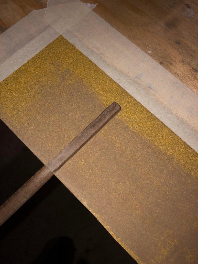
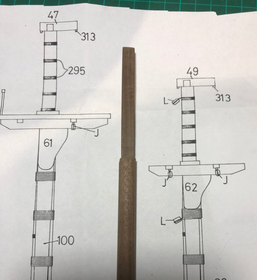
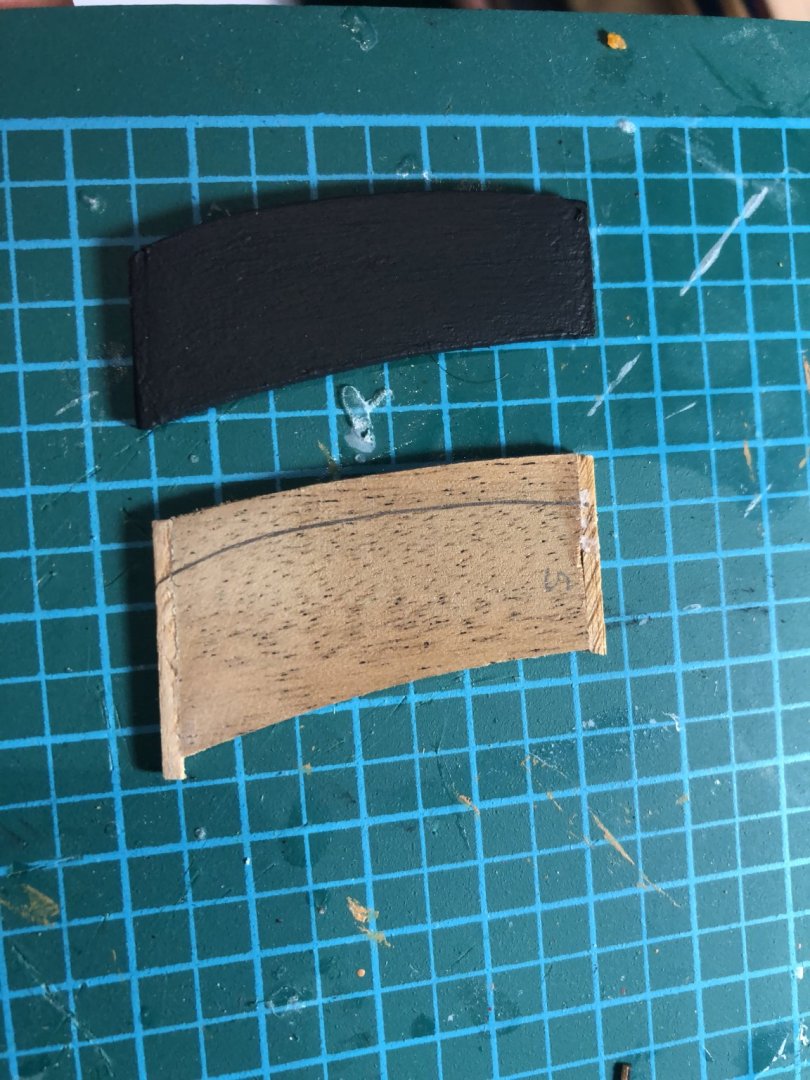
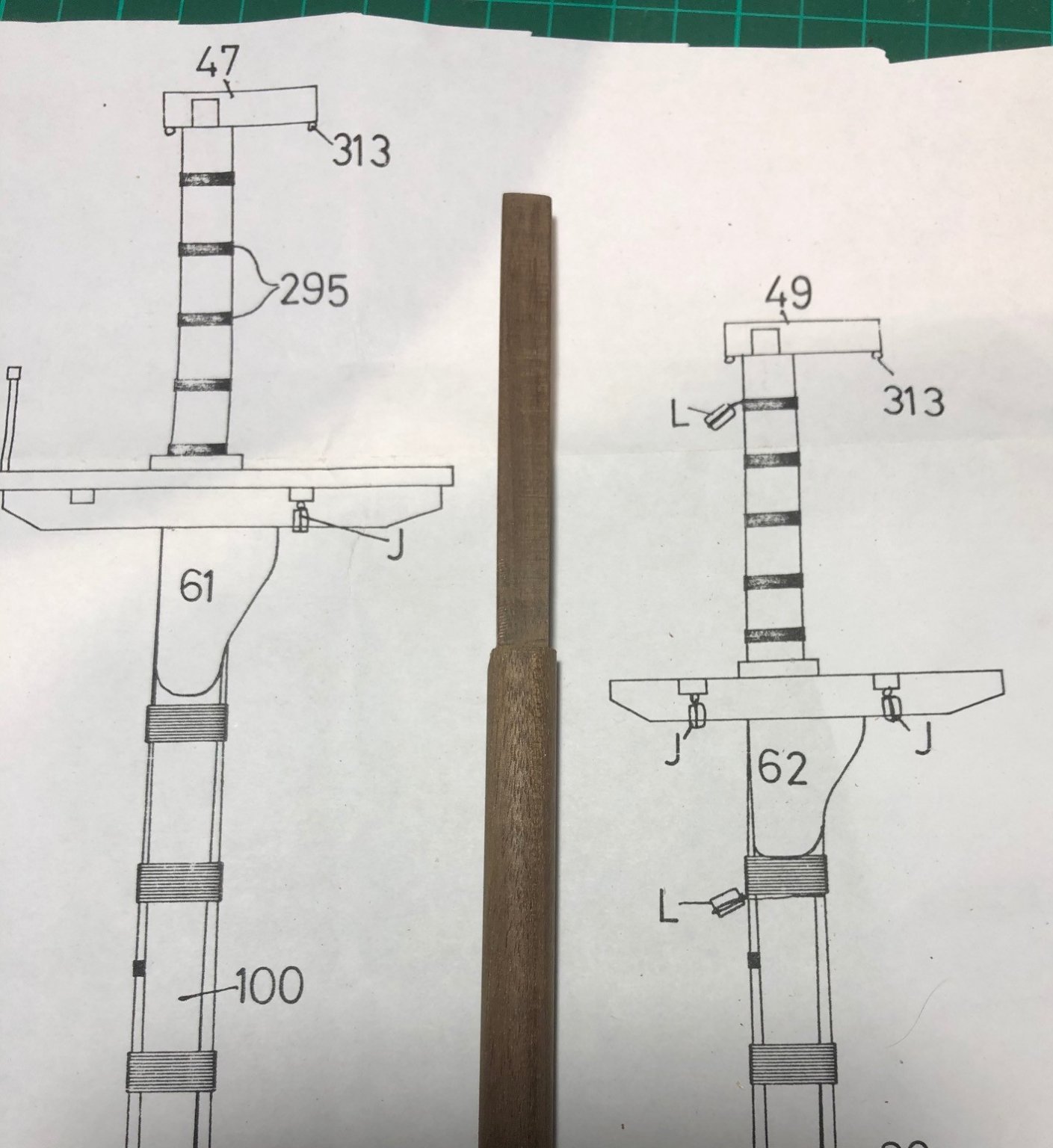
I then shaped the mast to receive the various cheeks, bibs and forward strengthening strip. I used a small razor plane to create the flat sections, painted the parts, and glued them all together having first attached the iron mast bands made from the black cartridge paper. I soaked the paper strips in water then washed them with 50% PVA which allowed them to slip and slide into position with ease.

-
Okay - 6 weeks have passed from since my last update; I guess the fact that I just grab and hour here or an hour there is not conducive to regular detailed blog entries. To be honest, I sit in the shadows watching the slickness of Rob's (ETHALION) and Jason's (JASON) efforts, complemented with stunning photos, that I'm not sure I have that much to add!
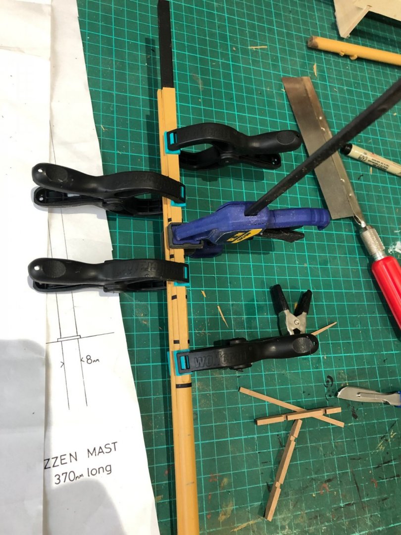
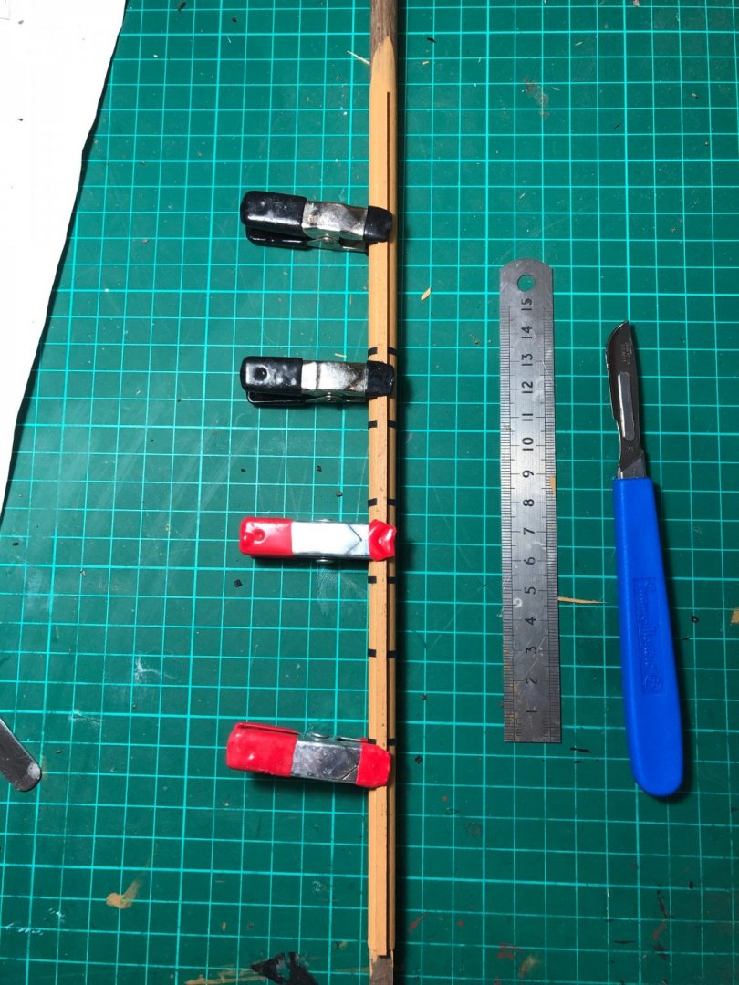
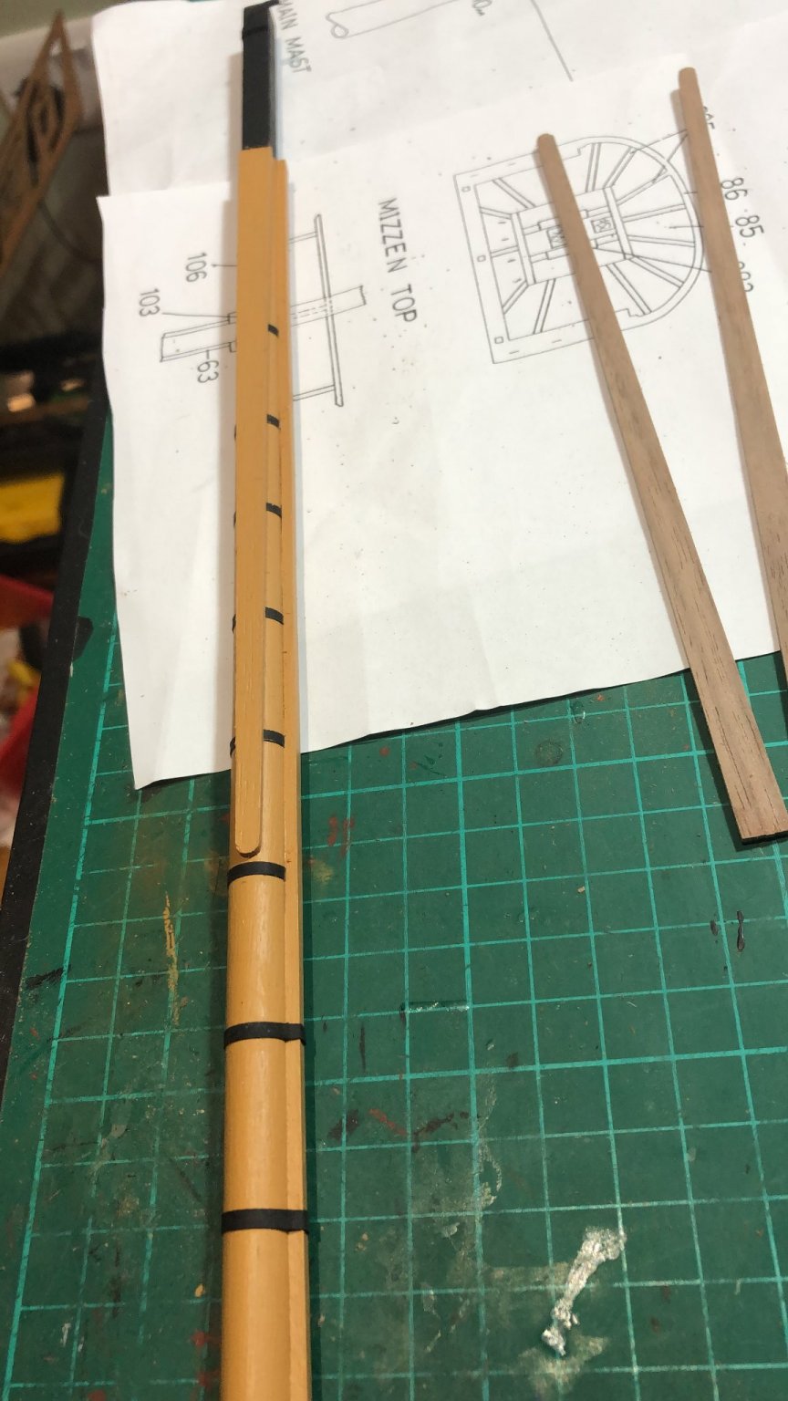
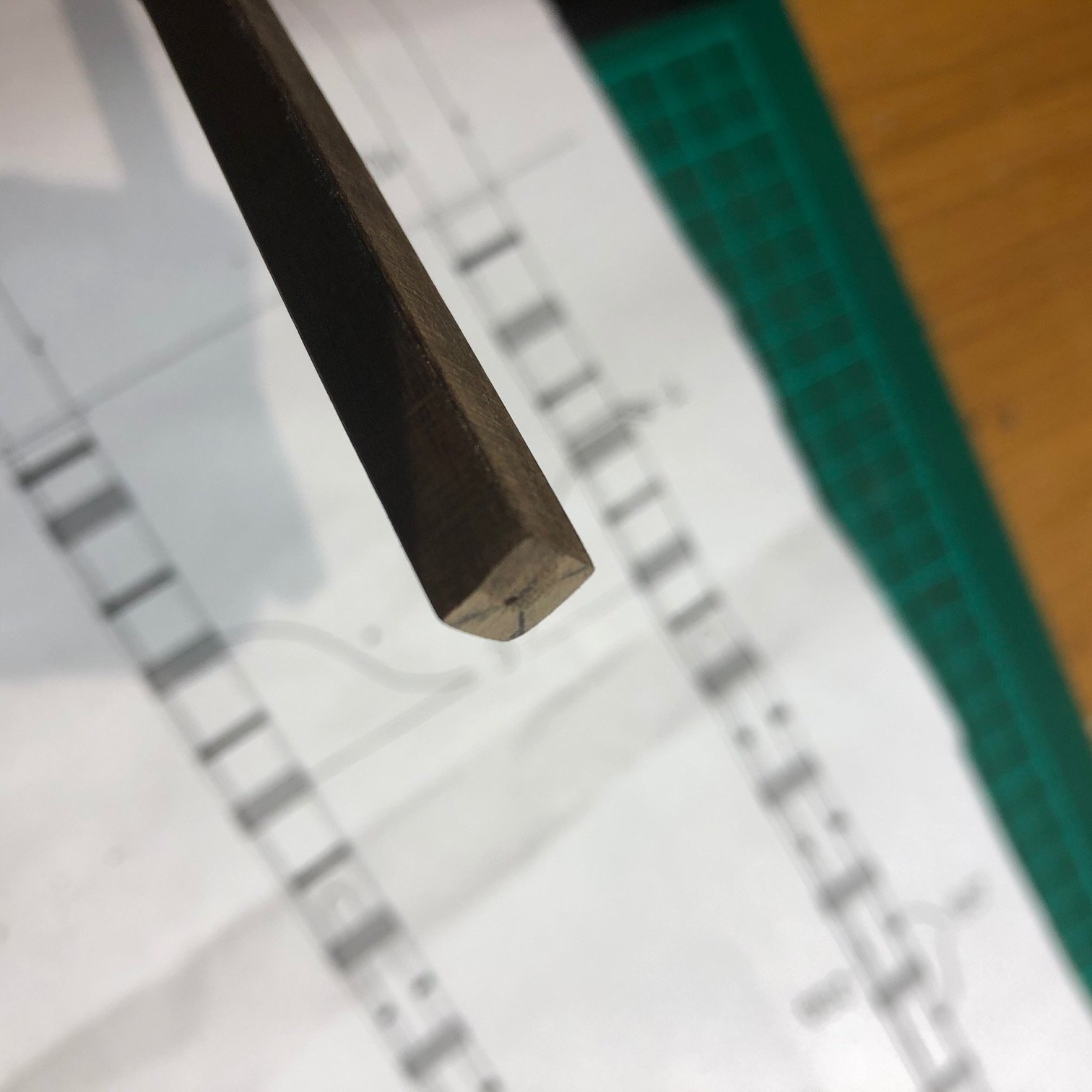
Anyway, I have finished the bulk of the hull - lots of tiddling up to do - so I have moved onto the masts...the boats can wait! I haven't made masts of this stature before so it was a journey of discovery trying to work out how to make square ends, octagonal sections and to taper masts to the correct diameter size.
I started with square ends at the mast head. To cut? to plane? to sand? I did the latter. I found the centre of the dowel and then marked (using my little lathe) the parallel lines that formed the square., cutting the four shallow arcs with my razor saw to help guide the process I then sanded carefully, constantly checking the line was not being overstepped and that the shape was correct. Patience was rewarded and they came out okay.


-
Thank you Bill and Vince for your advice. I will certainly try this method, especially transitioning via an octagonal shape however, I do have a lot of good quality walnut dowel which ideally I would like to use. The advice in one of my modelling books is to file the end square - again this seems a little rough and ready. I’ll continue to mull this one over.
Peter
-
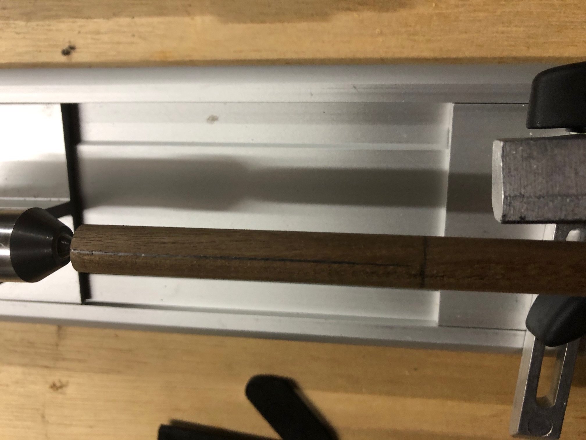
I am halfway through a Kit model of HMS DIANA (progress in the build blog section) - I have arrived at the ‘making the masts’ section. I can work most of the processes out and read up methods in various guides, I have a small lathe to allow me to shape the spars and yards and will experiment in due course. The area that perplexes me is the method by which the top section of the mast is cut square so that the main top and cross trees/trestle trees can be attached to the mast. I want the top section to be neat and correctly square so doing it by eye is fraught with danger. Any clues on how to turn the top section of 10mm walnut dowel into a true square?? Peter
-
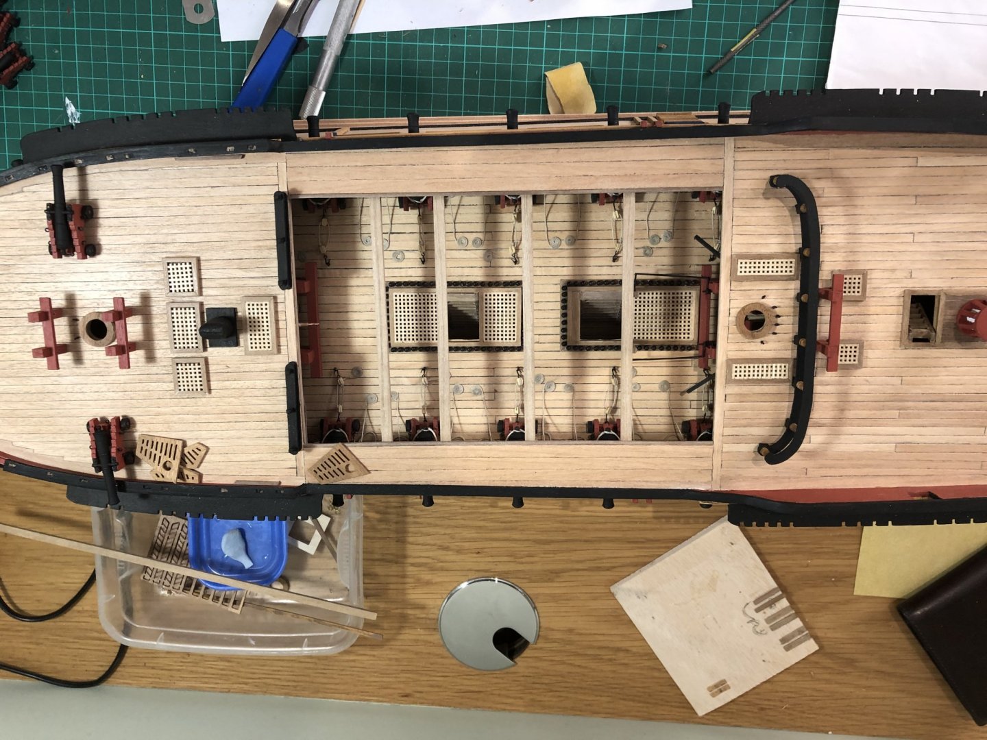
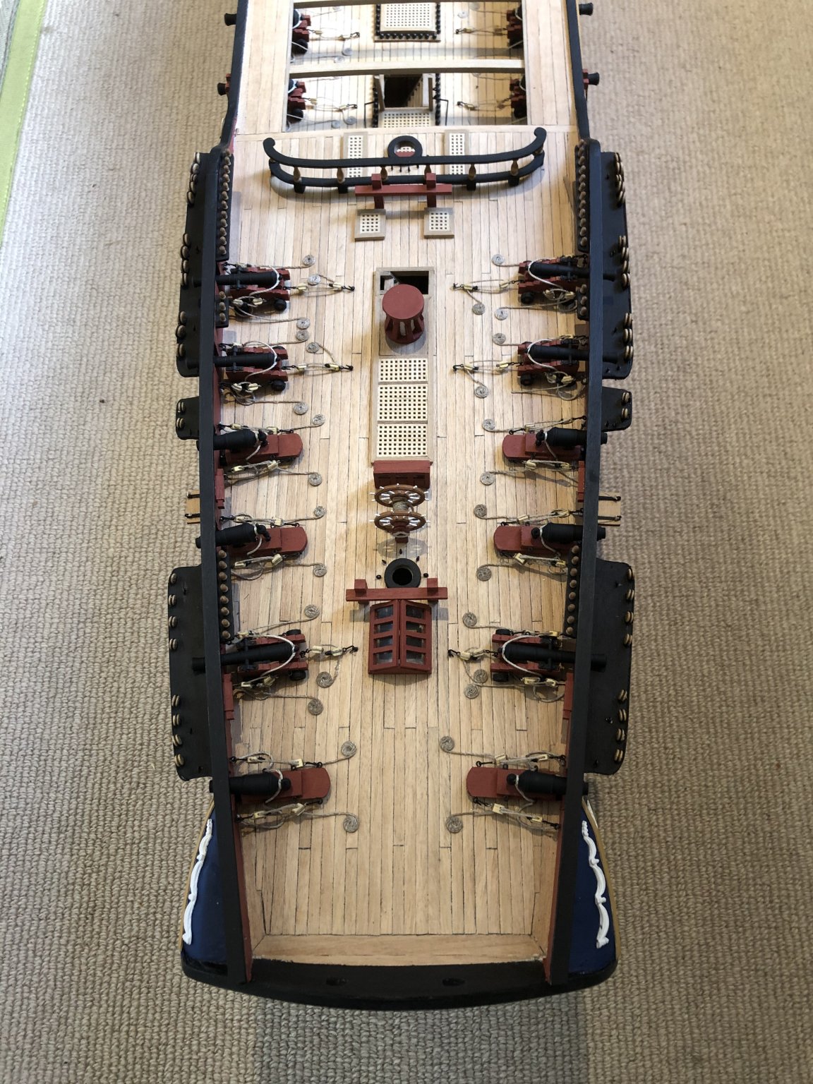
I have been remiss in updating the blog. Apologies so here are a few catch up pictures. I have completed the main deck, securing all the cannons, carronades and deck fittings and am now moving on to the bowsprit and masts... Ill try to be a little more diligent with my updates. Peter


- robdurant, p.hoek, Captain Poison and 8 others
-
 11
11
-
How is it going? Ill update my DIANA blog this week - hope all is on track. Peter
-
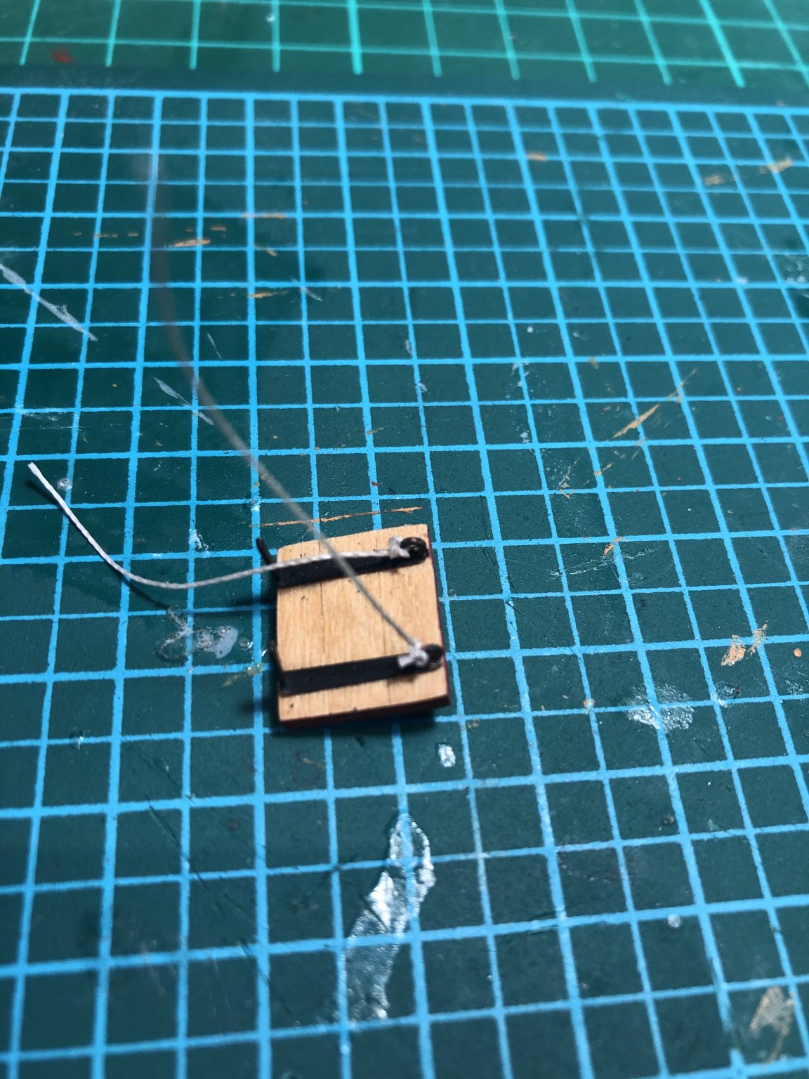
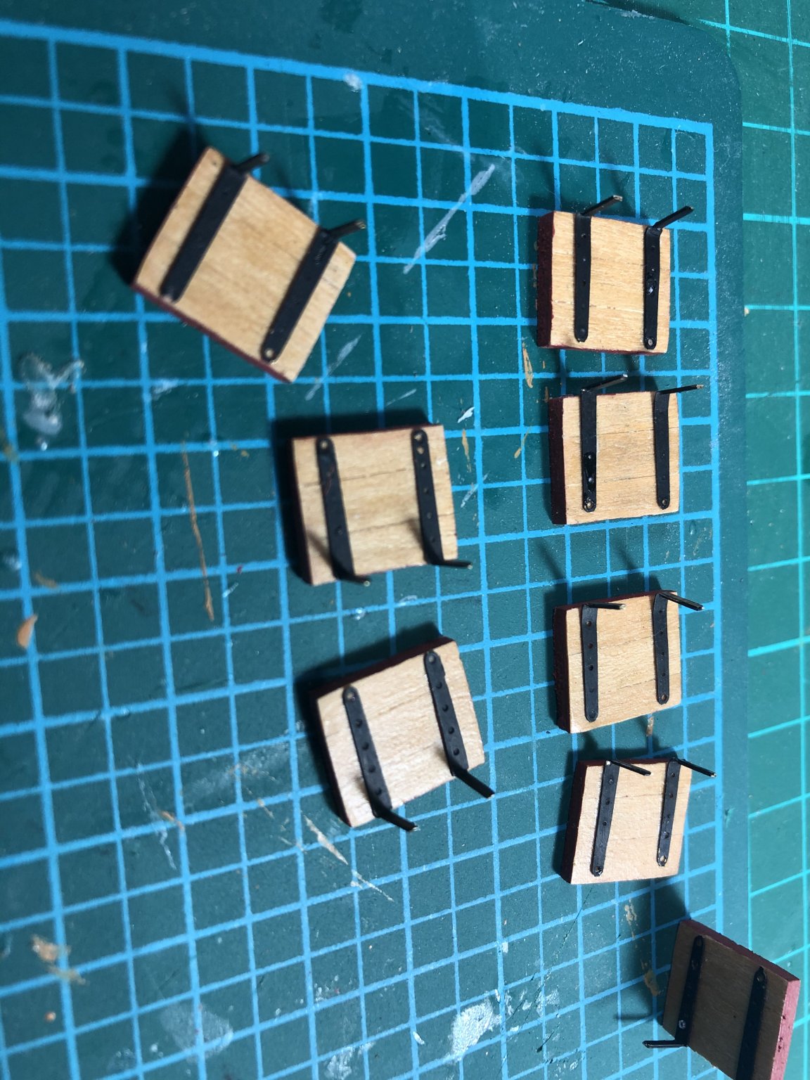
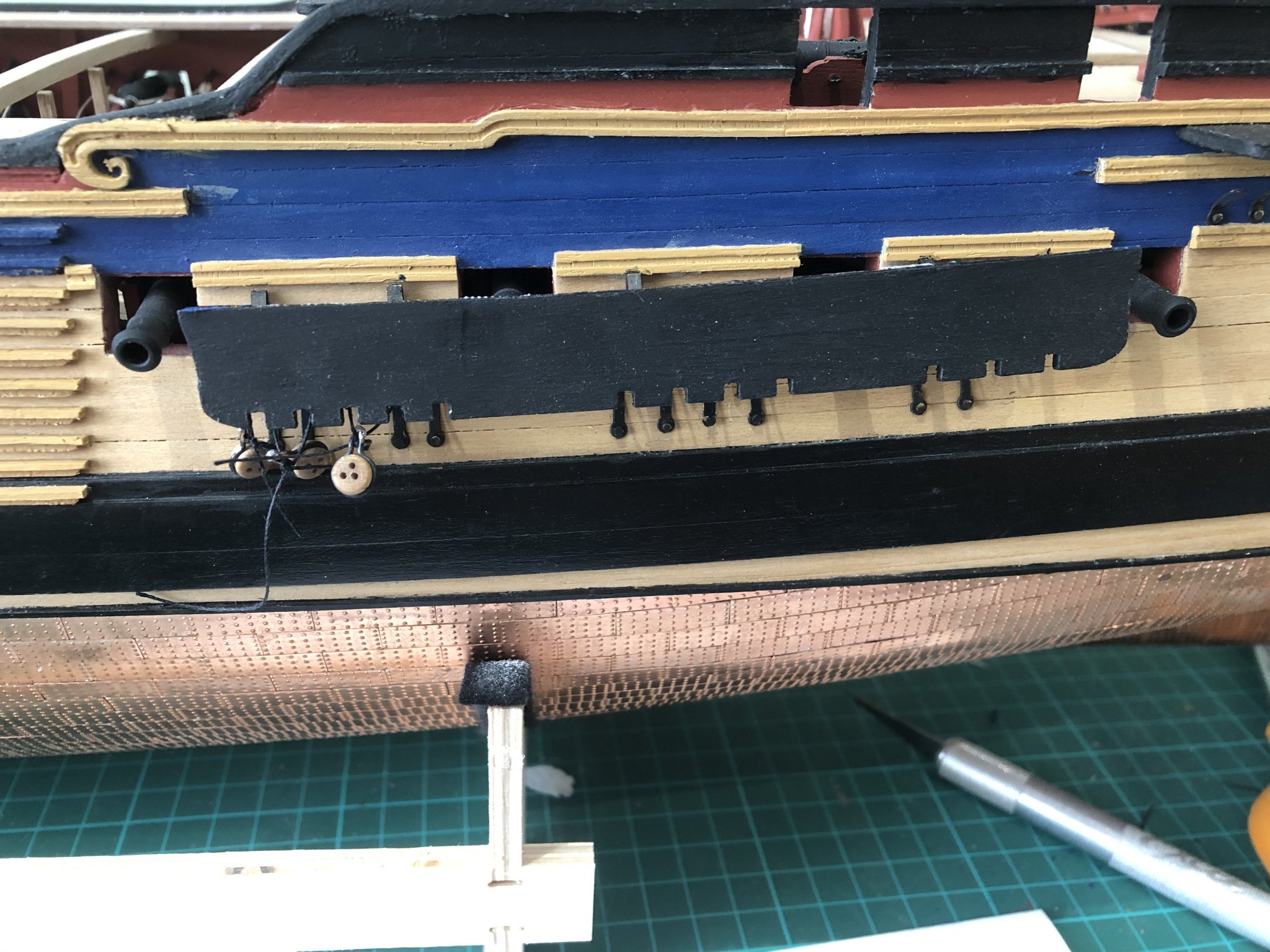
so with lining boards corrected, I attached the gunport lids. Fairly straightforward ….except the top of the forward gunport was too close to the sheer rails (the alignment problem again) which meant the lowering ropes would be either be very close to the lid or would enter the hull via the sheer rail which I don't think is accurate: I left them off. I used a little PVA glue on each line which, when it dried, meant the line was stiff enough to feed through the side-side holes and also look under tension (ish).
I'll finish the head rails next.
Keep smiling.
Peter

- mort stoll, Beef Wellington, p.hoek and 3 others
-
6
-
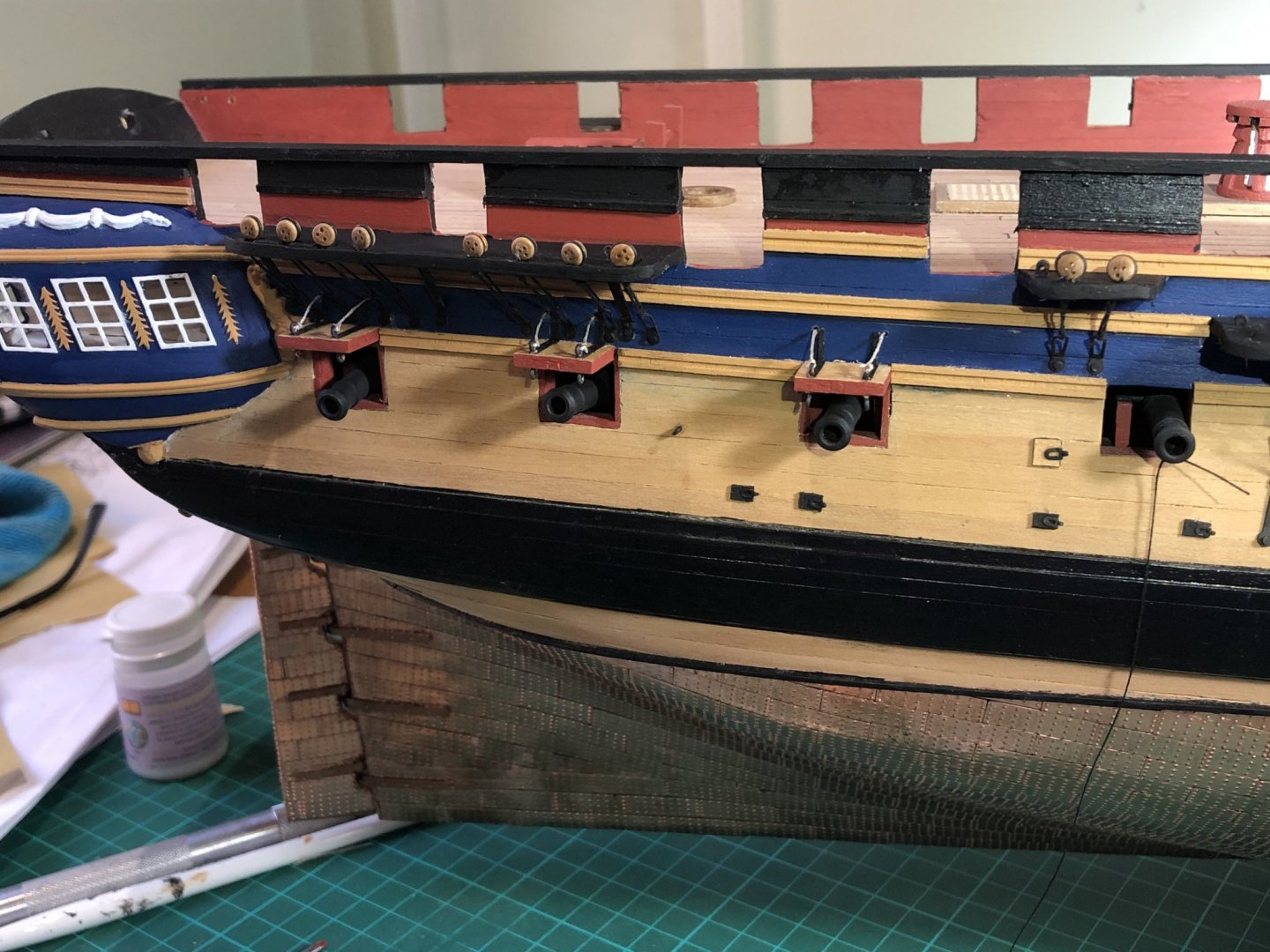
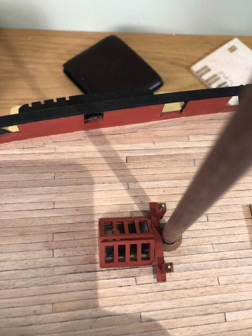
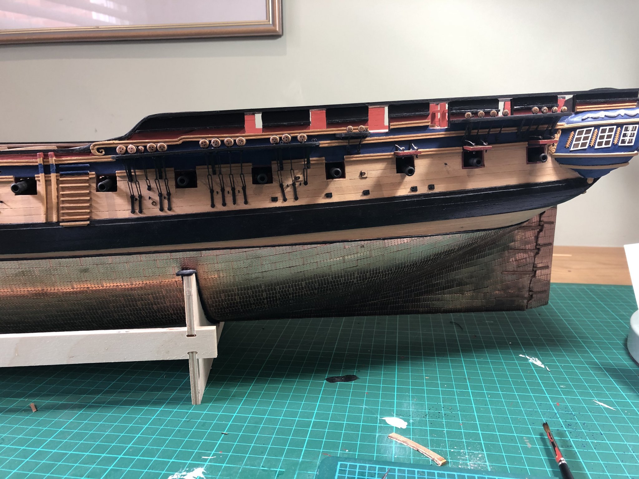
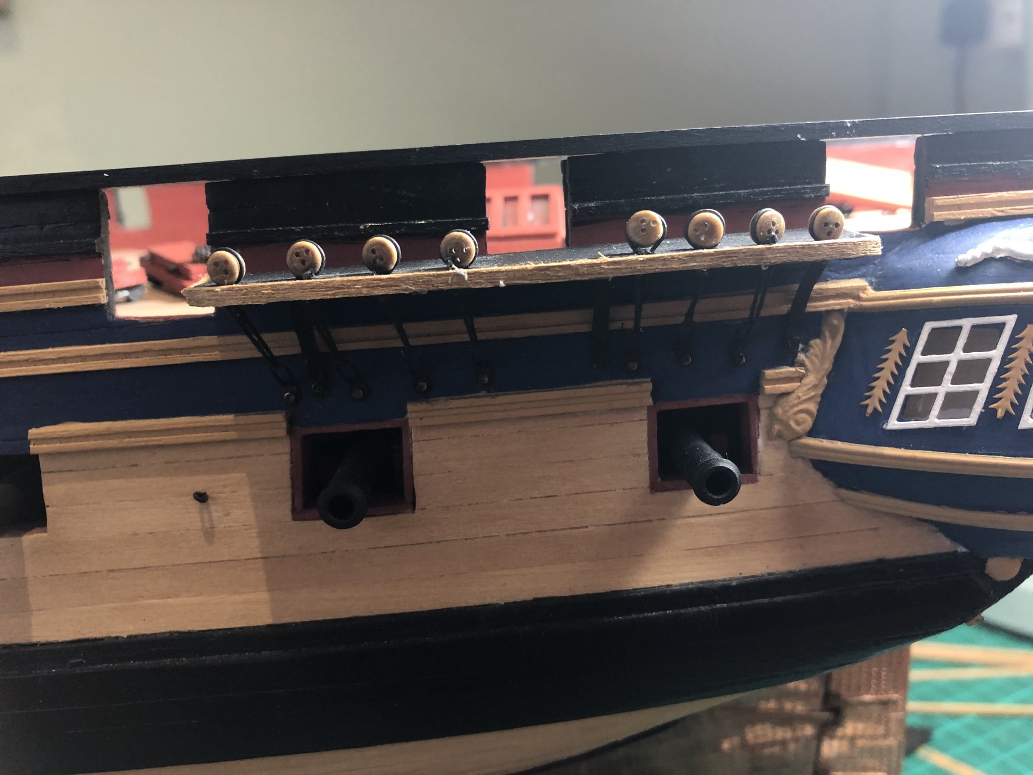
I then attached the various ship side fittings - scuppers, ventilator scuttles and oar ports. I used box wood to match the side...still haven't mastered the brass blackening process; it still seems to rub off with undue ease....so a combination of watered paint and partially blackened fittings. Next step was to fit the anchor linings which wasn't as easy as it should have been largely because of the slight misalignment of gunwale and the mizzen channel - the gap was too large, in addition the channel was too close (by 2mm) to No 1 gunport as a consequence of jiggling to ensure the various chain links didn't cross the gun openings. Can't be helped. I trimmed the lining to achieve the right size whilst also fixing 1x2mm wood strips to plug the gap and which also allowed room for the stunsail boom brackets to be fitted later. To compound it all, I then fitted the linings the wrong way round, well it is a learning process - start again, remove, replace!

-
An update. I persevered with the various channels and deadeye block fitting and before long they were completed. The smaller 3mm deadeyes blocks do rattle in the slots which made securing awkward, I needed a tiny piece of blu-tack to hold them whilst tying the note; once under tension they held their place. I also needed to be careful to not to try and force the 5mm deadeyes into the slots in too hard a fashion, unfortunately I did so on one occasion, rushing and not adjusting the size of the strap and the inevitable happened - the channel broke away from the ships side! Repairs were completed and blocks inserted properly. I covered the outside of the channels with trimmed 3x0.5mm walnut to close the deadeye slots, then sanded and painted it black. They don't look too bad....


-
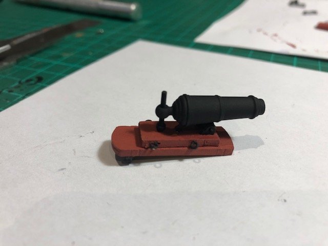
I inserted four of the eyebolts and attached the slide to the base and attached the rear wheels. The carronade sits on the central spigot allowing rotation whilst elevation is controlled by brass elevation screw - I have yet to fit the handle. I will then work the front of the carronade and insert the rest of the eyebolts.
Progress is maintained - 5 of the 8 made so far.
P
- Shipyard sid, GrandpaPhil, Richard44 and 1 other
-
4
-
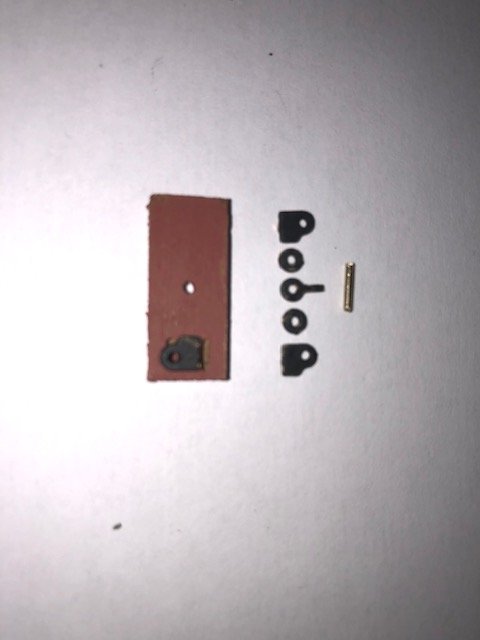
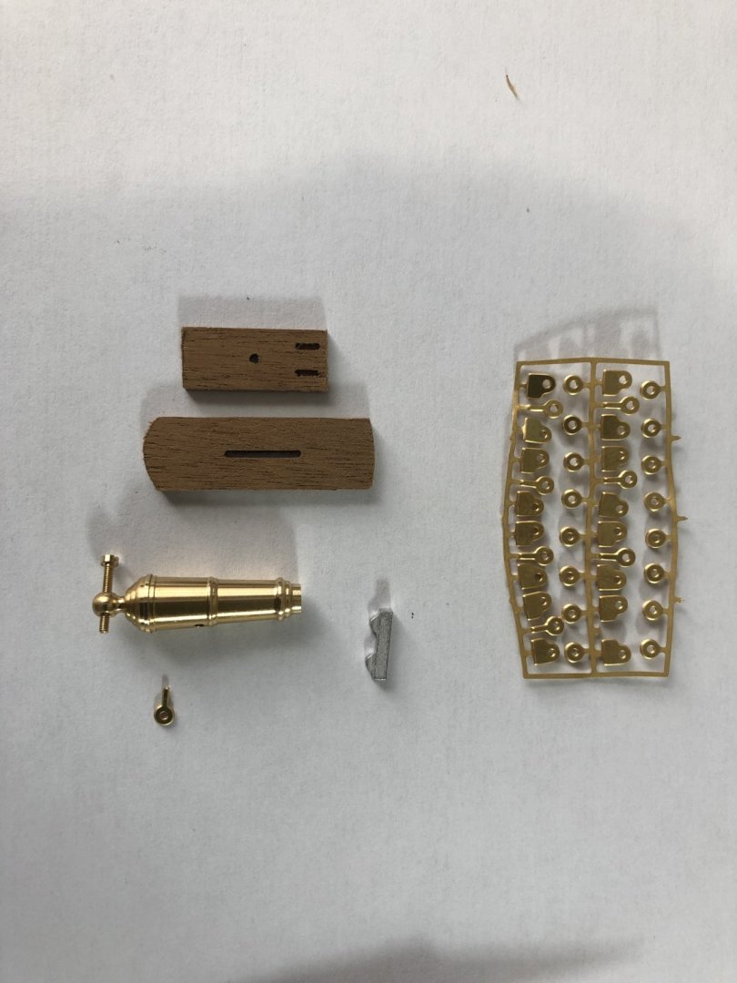
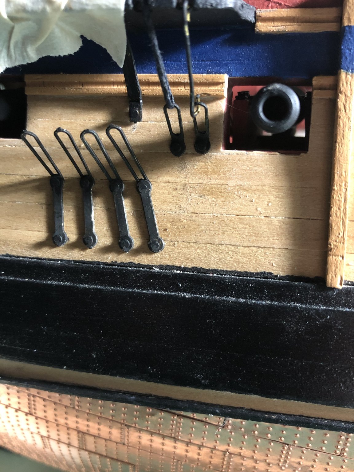
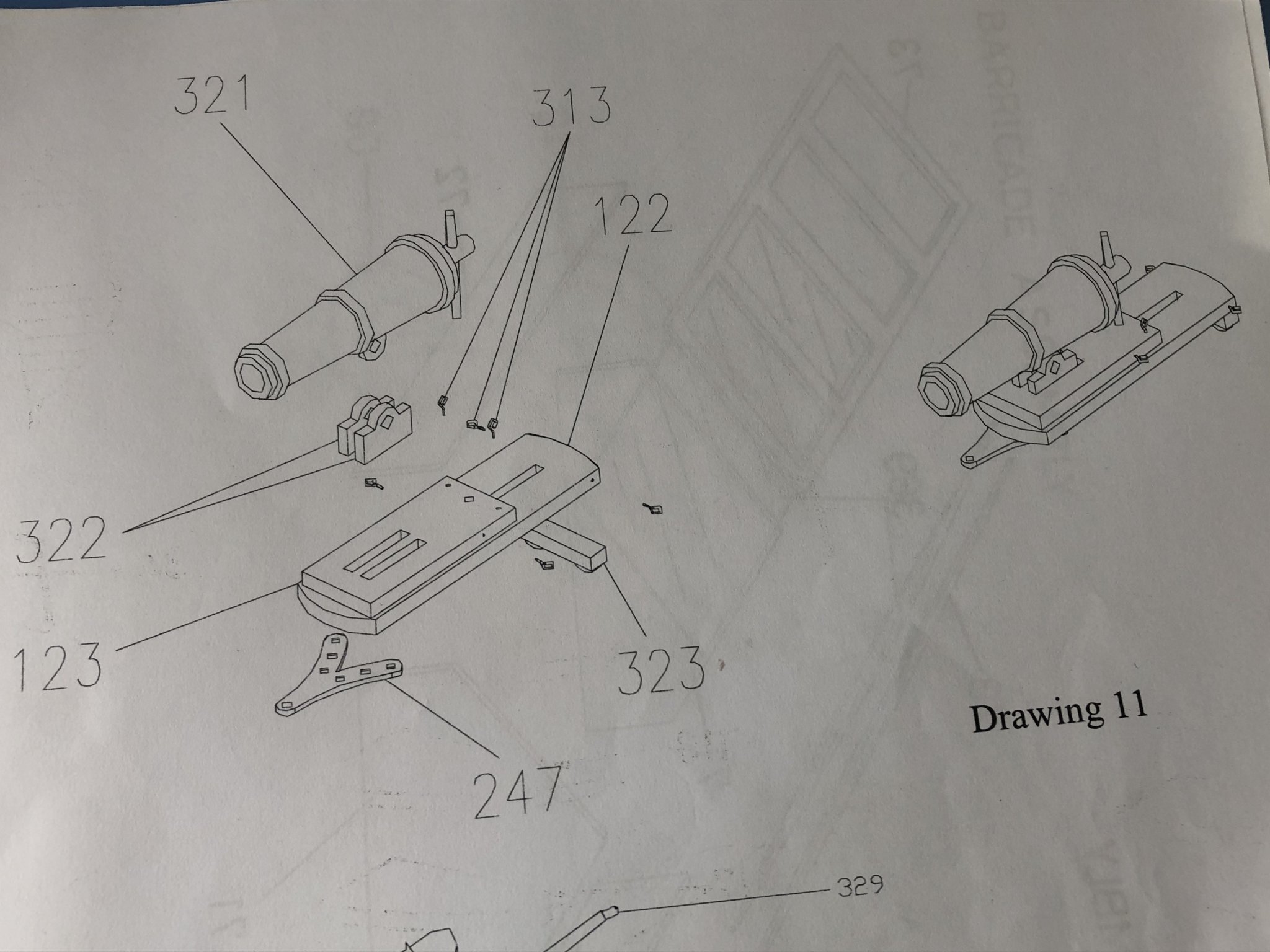
Tying blocks is a little repetitive so for variety, I cracked on with the carronades. As I mentioned above the instructions and supplied parts didn't align, however Jason forwarded to me a revised set (see below) which helped clear up the confusion. The assembly is a little fiddly but reasonably straight forward.
https://modelshipworld.com/applications/core/interface/file/attachment.php?id=610306
I followed the sequence in the attachment and the product (not complete) looks good. Remember to drill out the brass holes with a 1mm drill - the fittings are tight and easily jam therefore this saves much frustration. The fittings for the trunnion brackets on the slide are too tight and I had to length them gently with the 1mm drill; likewise the 1.5mm wire fits neatly through the slide but the hole in the main carriage is only 1mm wide - again needs rejigging.
I painted the components before removing from the brass sheet...it came off in assembly! No problem - touch up at the end.
P

-
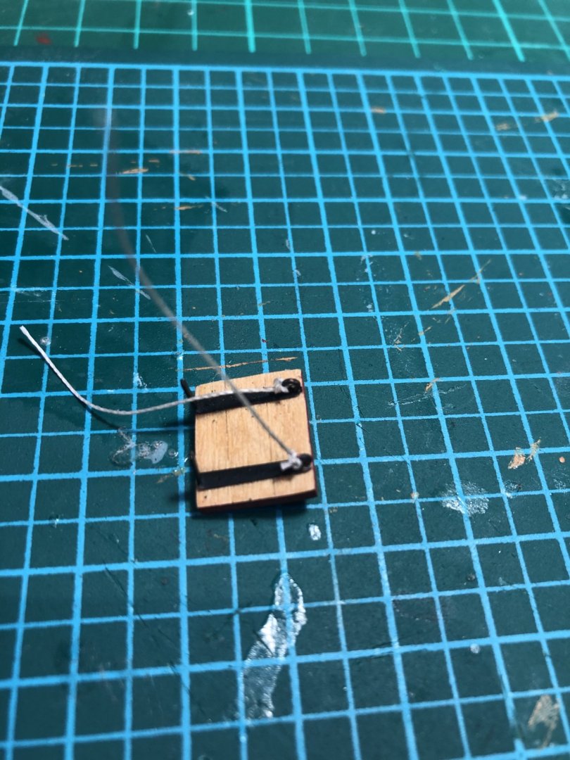
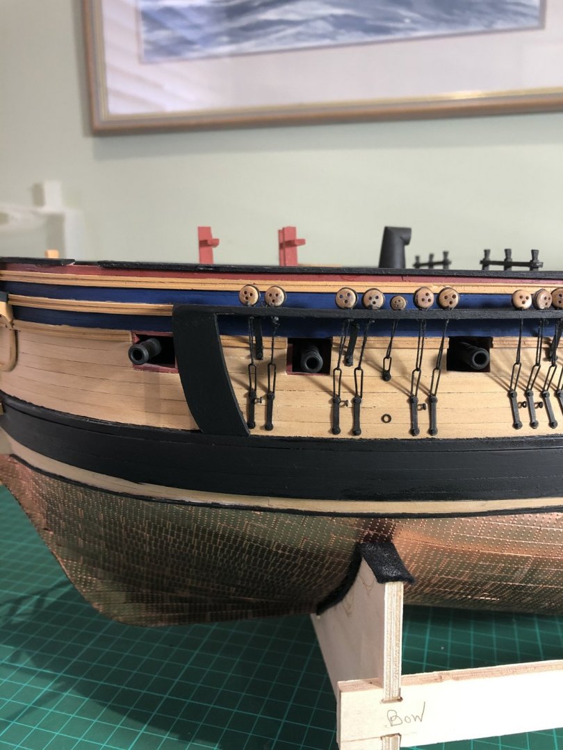
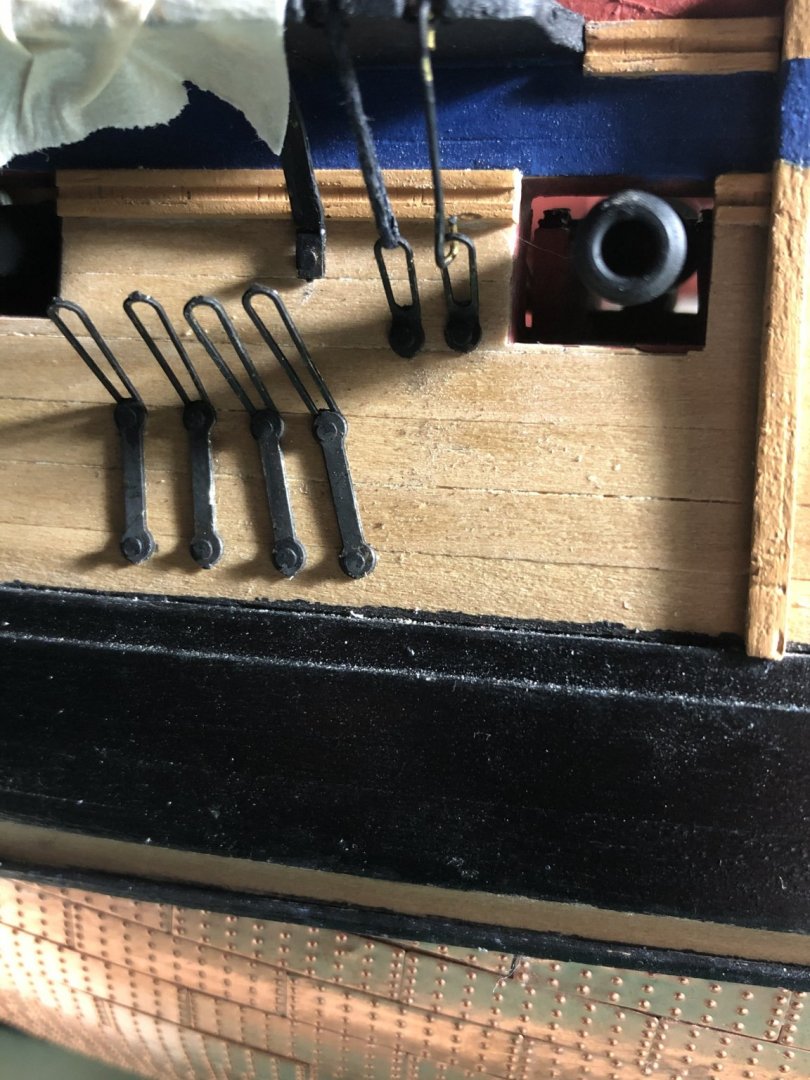
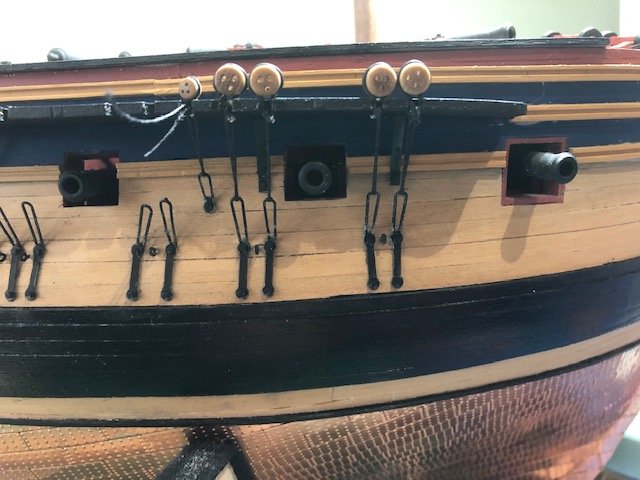
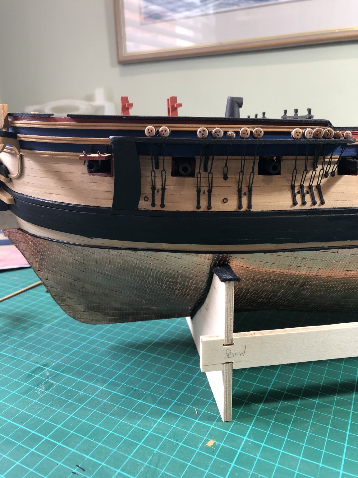
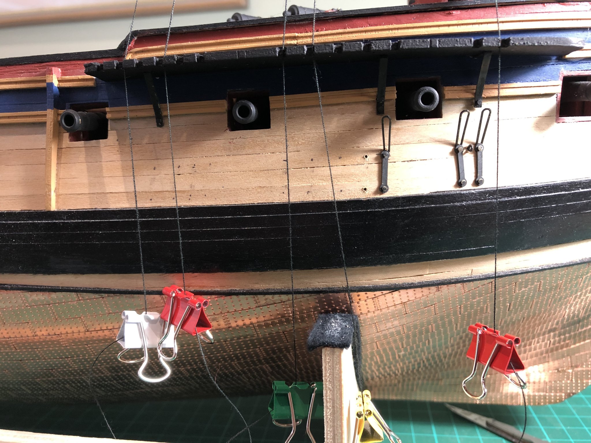
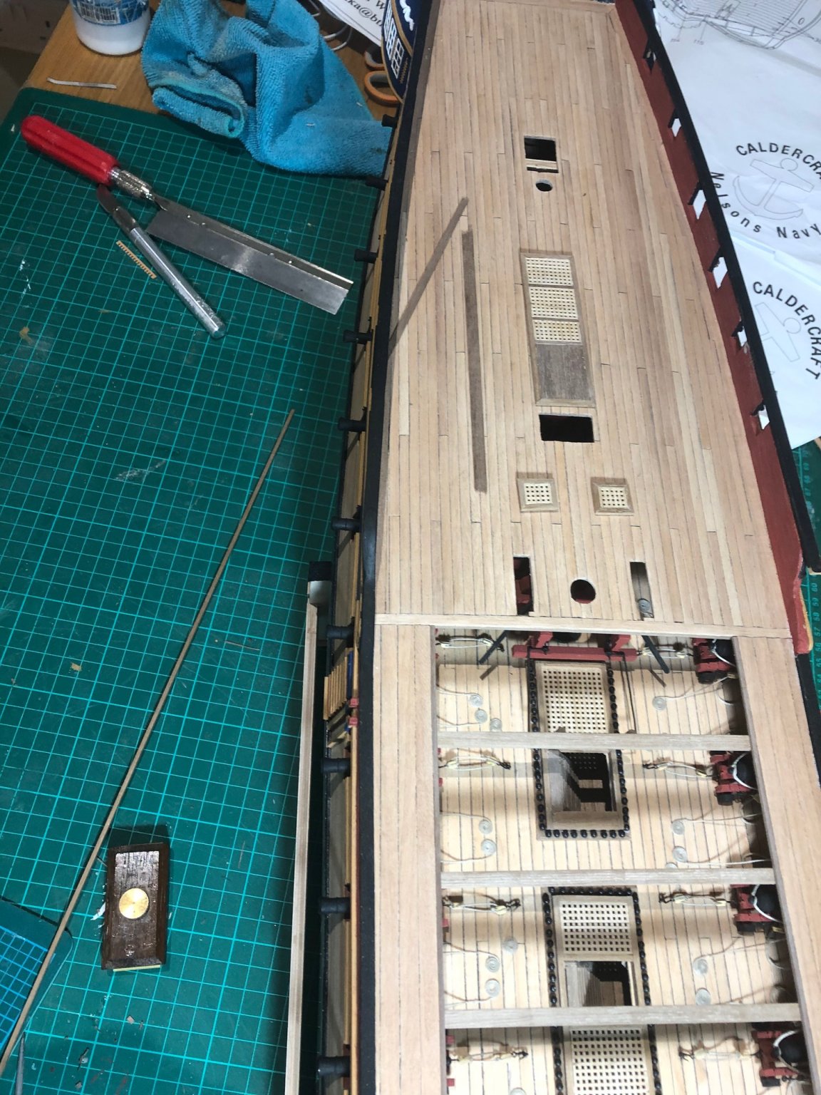
A couple of weeks since the last post so time for an update. progress has been slow but steady...we inch forward! I completed the chain links on both sides of the hull and then inserted the deadeye blocks into the strops - not all fitted well as can be seen. I then soldered (actually my son did) the eyes closed.
The choice was how to attach the block to the upper chain links. The instructions direct the use of 0.5mm wire; I tried this but could not get a uniform line, the all had very slight kinks, were uneven in shape and were all of differing lengths - marginal but apparent to the eye. I therefore followed Ray's advice and used 0.5mm black cordage. By tying a slip note at one end, the line can be pulled under tension to give a even set of upper chain links. Once they are all complete I will wash them in dilute PVA which will help preserve the tensions. Not perfect yet, for a first time, they are not too bad. I have completed the stbd side and will crack port over the next few days.
You might notice that one gun has a line around its barrel; the glue has been dislodged and it is now loose on the gundeck! arrgghh! I didn't want it to fall into the innards of the ship, hence the line. I will have to think about how to re-secure it!
Peter
.jpg.dd50bc36ea1f6b5edadaeafc32f09226.jpg)
.jpg.a0f3f50854c095f2470db355c8fbe9b6.jpg)
-
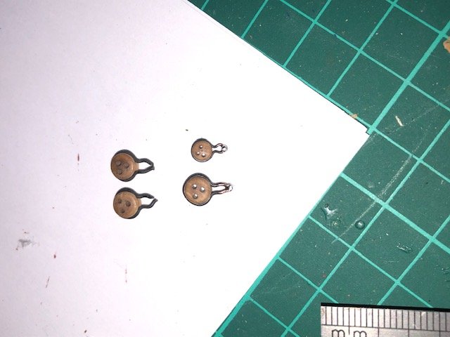
Hi Jason. Thank you for the advice - I will await the response from the guys at Caldercraft. I think I have your very nice brass carronades - they are certainly different to the ones shown in Rob and Ray's build blogs - the threaded screw is well made and fits beautifully. On the underside of the barrel, in the middle, is a single hole, this indicates to me there should be a some sort of hinge that could then connect onto the gun base via the D shaped trunnion brackets and a short axle piece of brass wire (1mm). Unfortunately the small ring with a short leg is too small to fit into the underside and would be too weak to carry the weight of the barrel (it will flop) , the threaded screw (for adjusting the elevation) doesn't align with the hole on the base but perhaps it shouldn't and the hole is the location for the thick wire you referenced above that would allow the top section of the base to slide back when reloading! I don't know what the additional brass rings are for...washers?
Hmmm not immediately clear! I'm in no rush - I can wait.
Peter

- GrandpaPhil and JpR62
-
2
-
Quick update.
Jason - thank you for your advice on the mizzen mast. I am going to adjust the position of the Skylight aft very slightly (will infill the deck planking) to open up a little more space for the pin rail; I think there is room for the wheel. I need space to be able to secure the rigging and retain the visual proportions. I don’t have any extensive tools other than a drill, vice and a few sharp modelling knives! If I decide to do another I might invest in a couple time saving devices - I’ll come back for guidance in due course! The ladder will do.
I have paused on the main deck fittings as the carbonnades have perplexed me and I have sought advice from Caldercraft. The parts supplied don’t match with the instructions booklet and I can really work out how to secure a comparatively heavy carronade to the wooden gun base in a manner that would have been in the real world. I have therefore started attaching the preventer links to the side as well as some of the other fittings. I have a little soldering iron enroute from Amazon after which I will work out how to secure the brass wire to the dead eyes.
Onwards! Peter

-
-
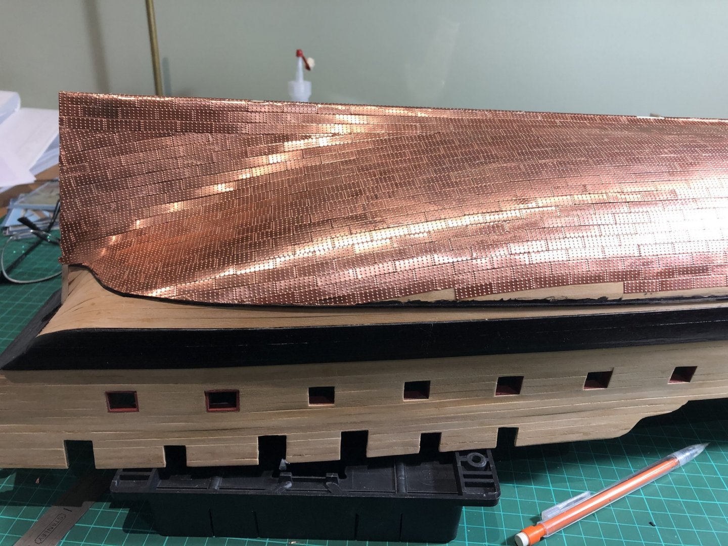
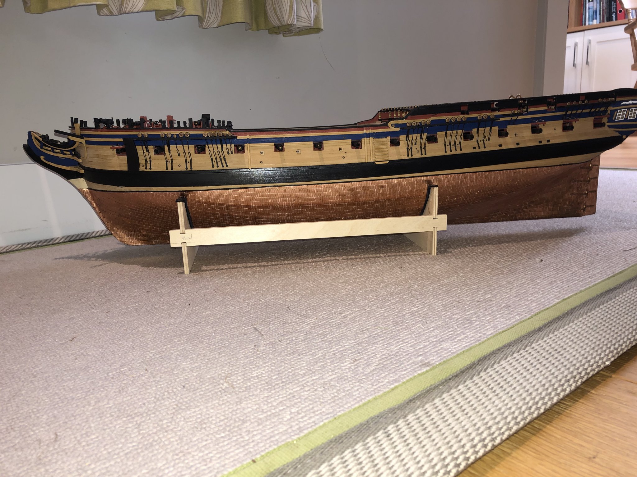
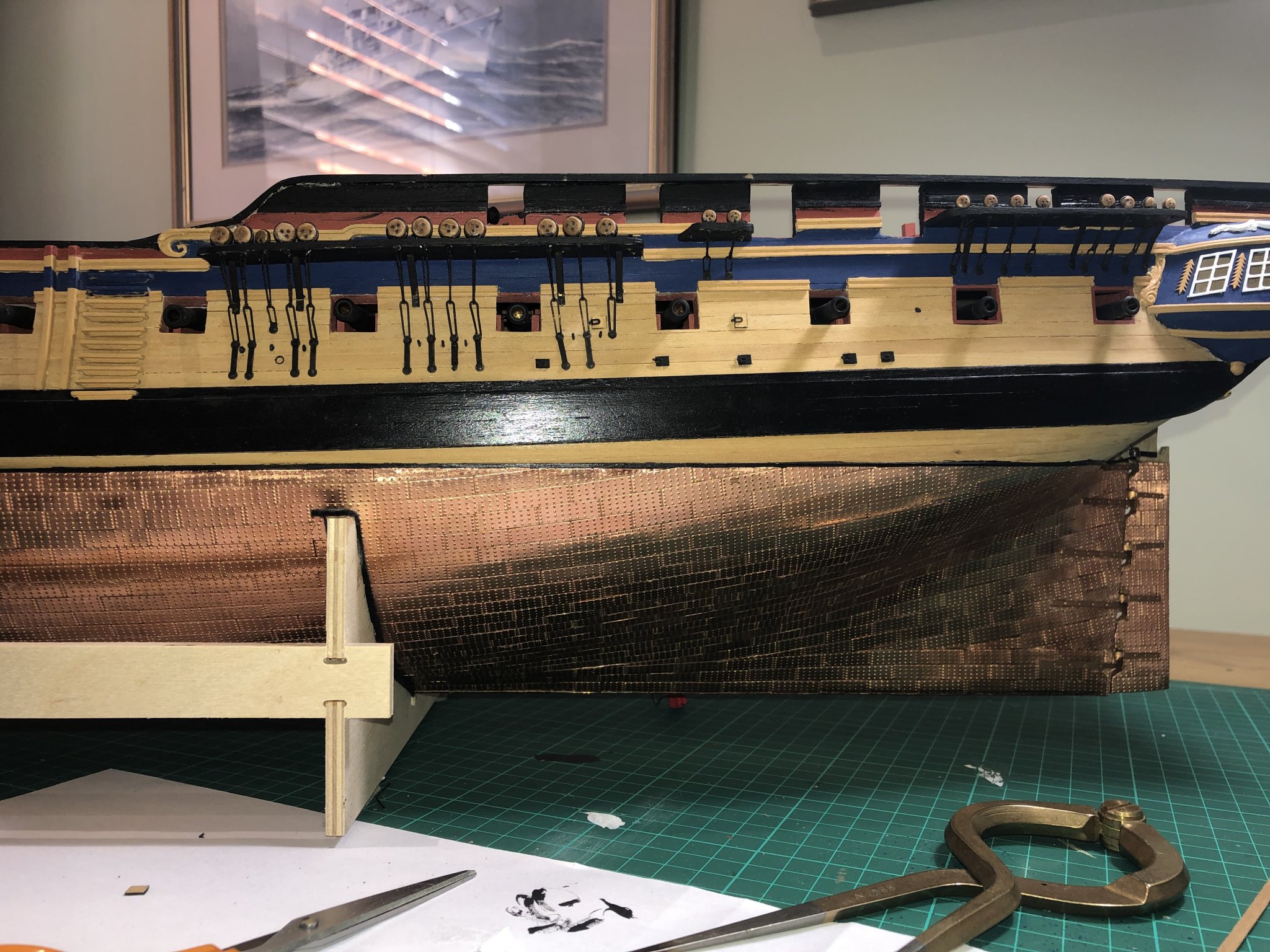
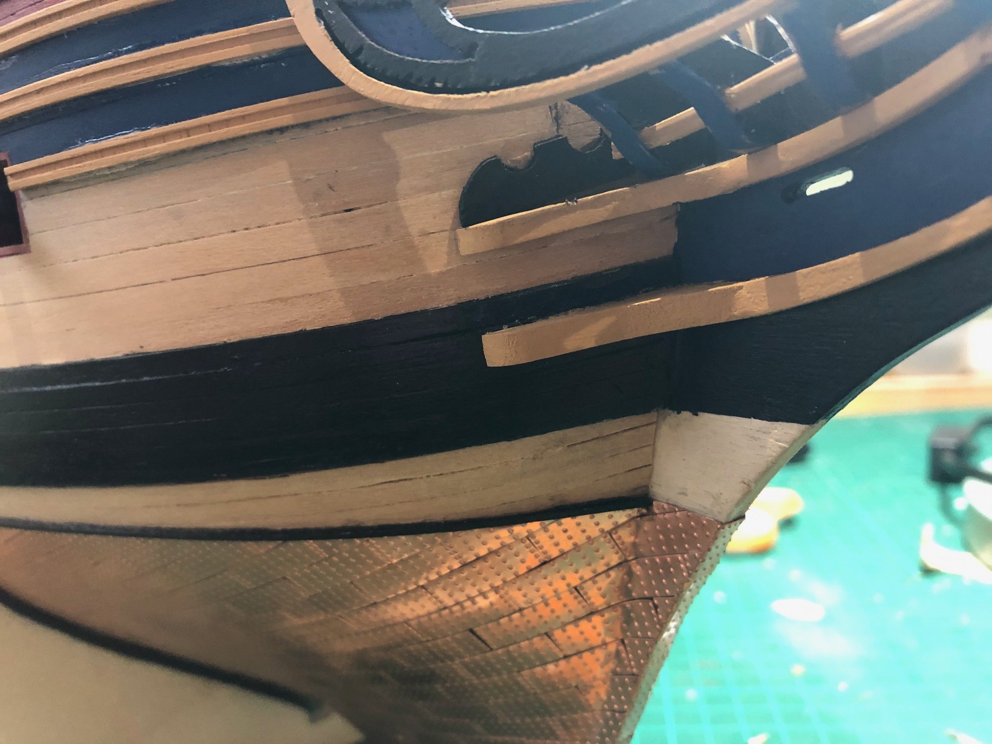
David - the copper work takes time and I was not particularly good or patient. I used a very mild cyno glue, had a bottle of acetone nearby to remove any excess and then just ploughed though it very steadily. 100 tiles or so would make me booz eyed so, I took lots of breaks and did other things to add variety - in my case the guns. I also fixed a 1x1mm piece of wood on the waterline to give a neat edge for the tiles to abut to. 'Slowly, slowly catch the monkey' as my Dad used to say! It does look good when it is finished.
- BenD, gieb8688, Shipyard sid and 2 others
-
5
-
The next task was attaching the quarterdeck fittings. On the plans, the skylight and the bitts are very close the mast; almost touching. To check the alignment, I inserted the mizzen mast …..hhmmm! In the plans the mizzen mast does lie aft - presumably by design so that the mast takes the tension created by the force of the wind whilst transferring the force into the hull through he stays (all the masts lie slightly aft). The main mast and foremast nest neatly into the precut slots - the mizzen is very tight and doesn't drop into the slots easily, I ma sure I checked it when the gun deck was fitted, however something seems amiss and seems overly skewed...I think it should be close tot he vertical. Not sure what to do here. Any thoughts?
When in doubt, stop...do something else whilst mulling over things.
Peter
-
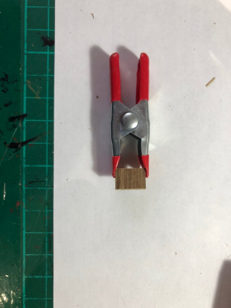
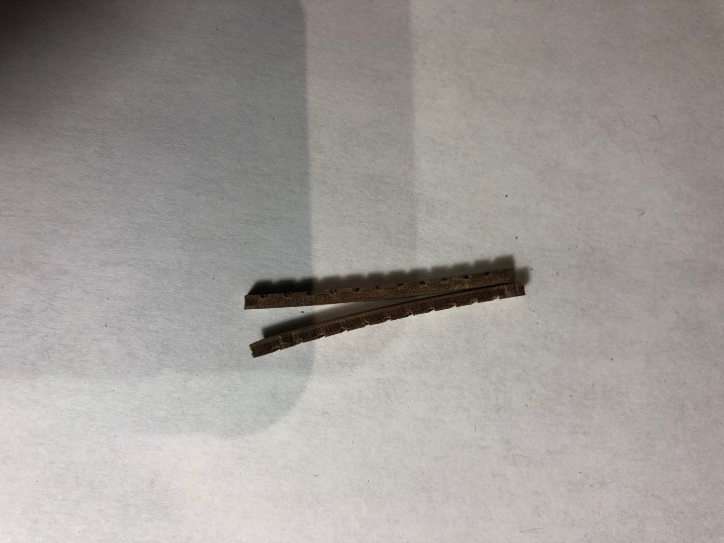
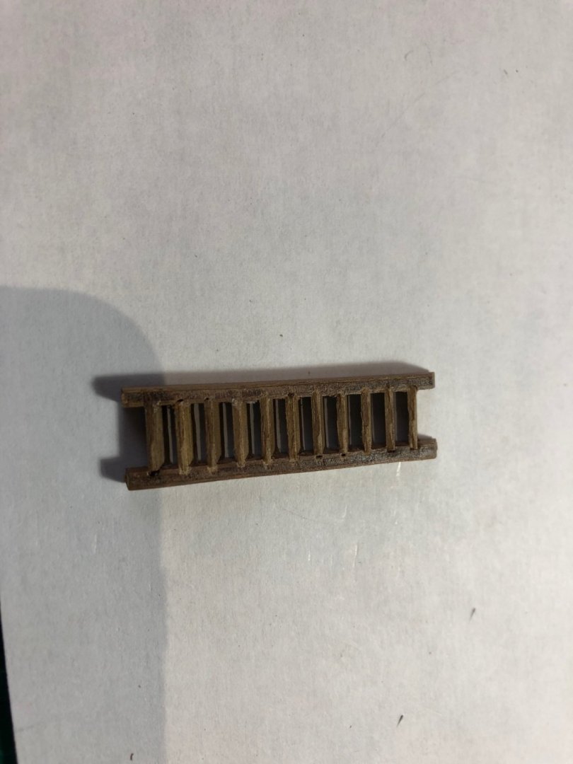
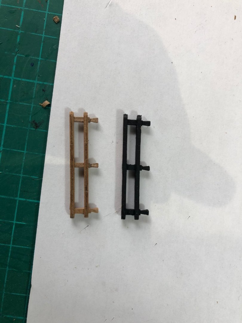
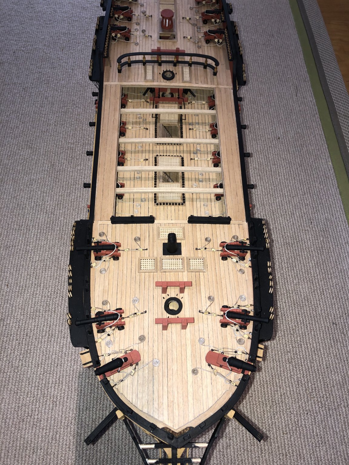
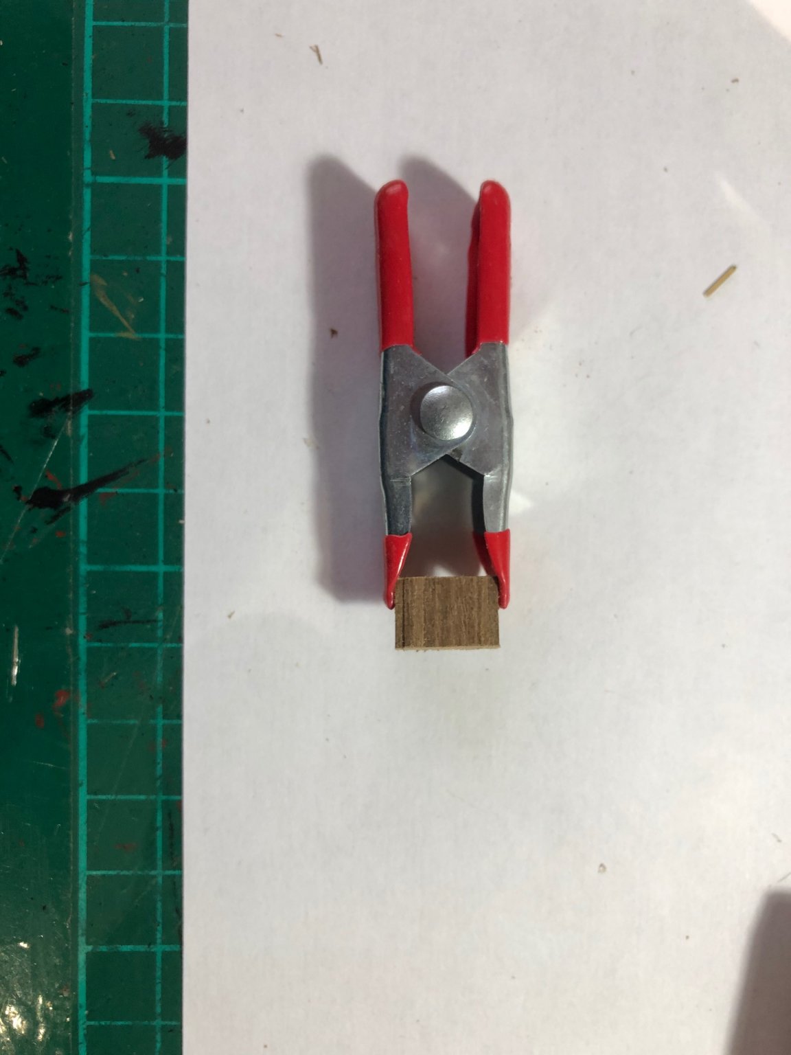
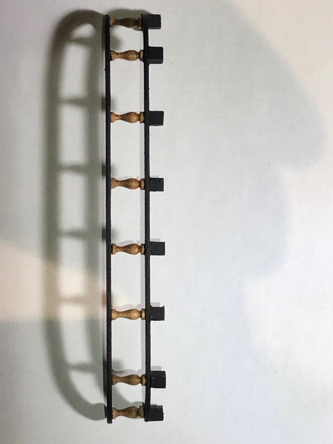
Things that didn't go so well. I have to say, I have problems with ladders in this kit - I don't like the wood, the cut or ...the final look! Sadly, I don't have the machinery to make alternatives so I have had to persevere with the items supplied. I have been careful to cut the ladder steps to the exact size and have tried to straighten the ladder side wood but they are too fragile and tend to delaminate easily. I managed to attach the top and bottom steps, then inserted the part assembled ladder into a small vice to hold the tension, and to stop the sides popping open, as each step was inserted (they are quite stiff fittings) - I used some superglue to ensure the fittings held. It looks coarse and clumsy even with a fine sand and a light varnish....good job it is hidden away!
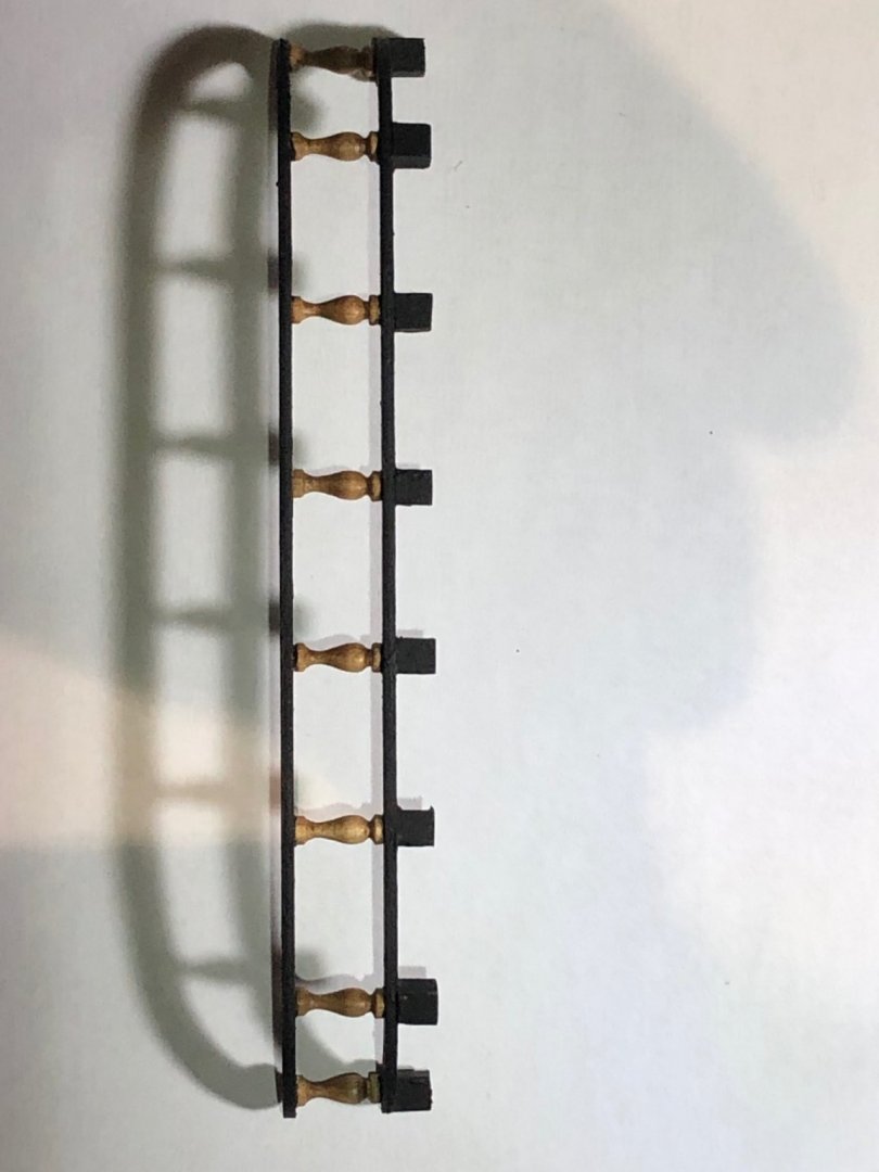
More pleasing was the central barricade - I decided to leave the central columns unpainted (just a light varnish0 which I think makes a more pleasing fitting.
Forwards...backwards!
- p.hoek, mort stoll, GrandpaPhil and 2 others
-
5
-
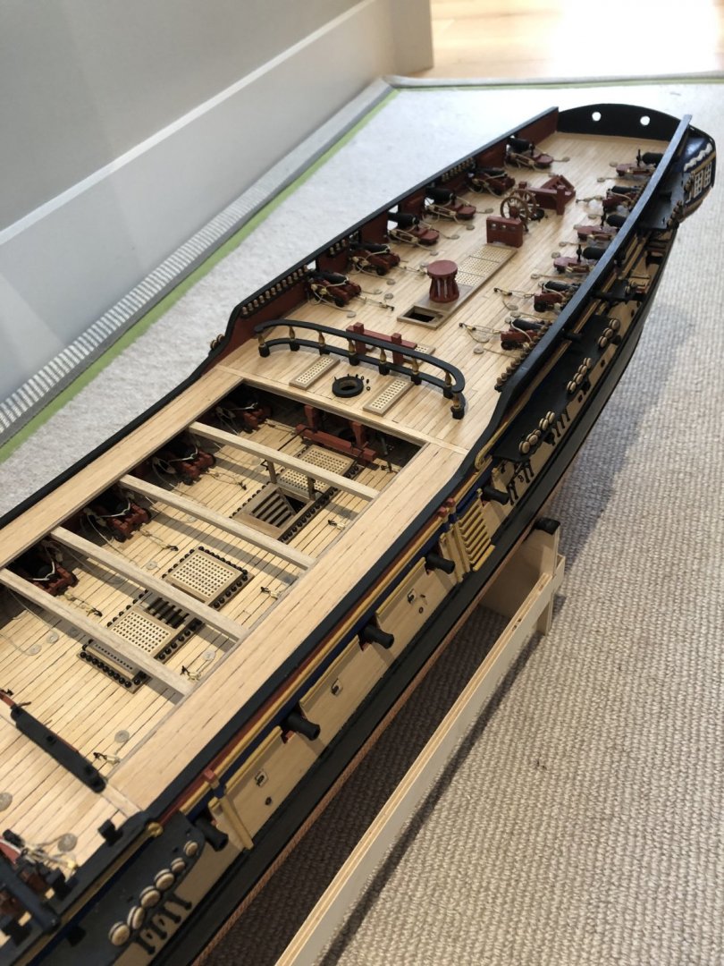
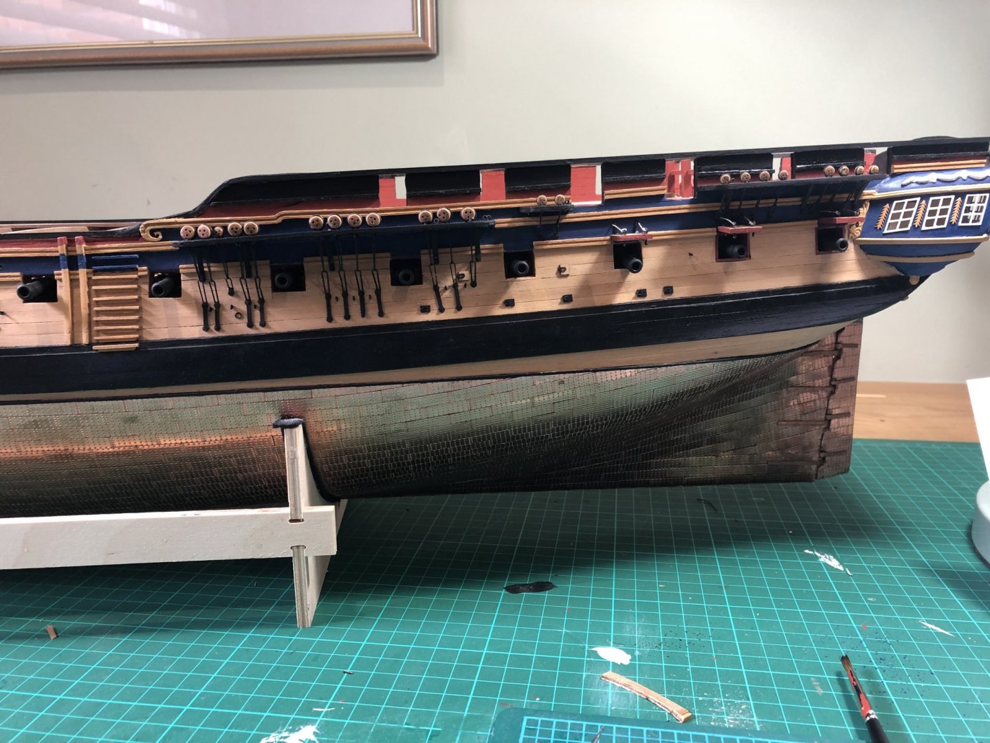
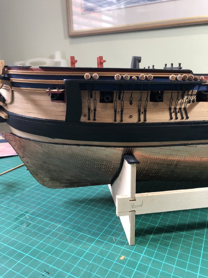
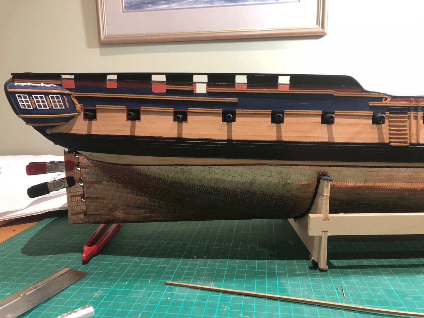
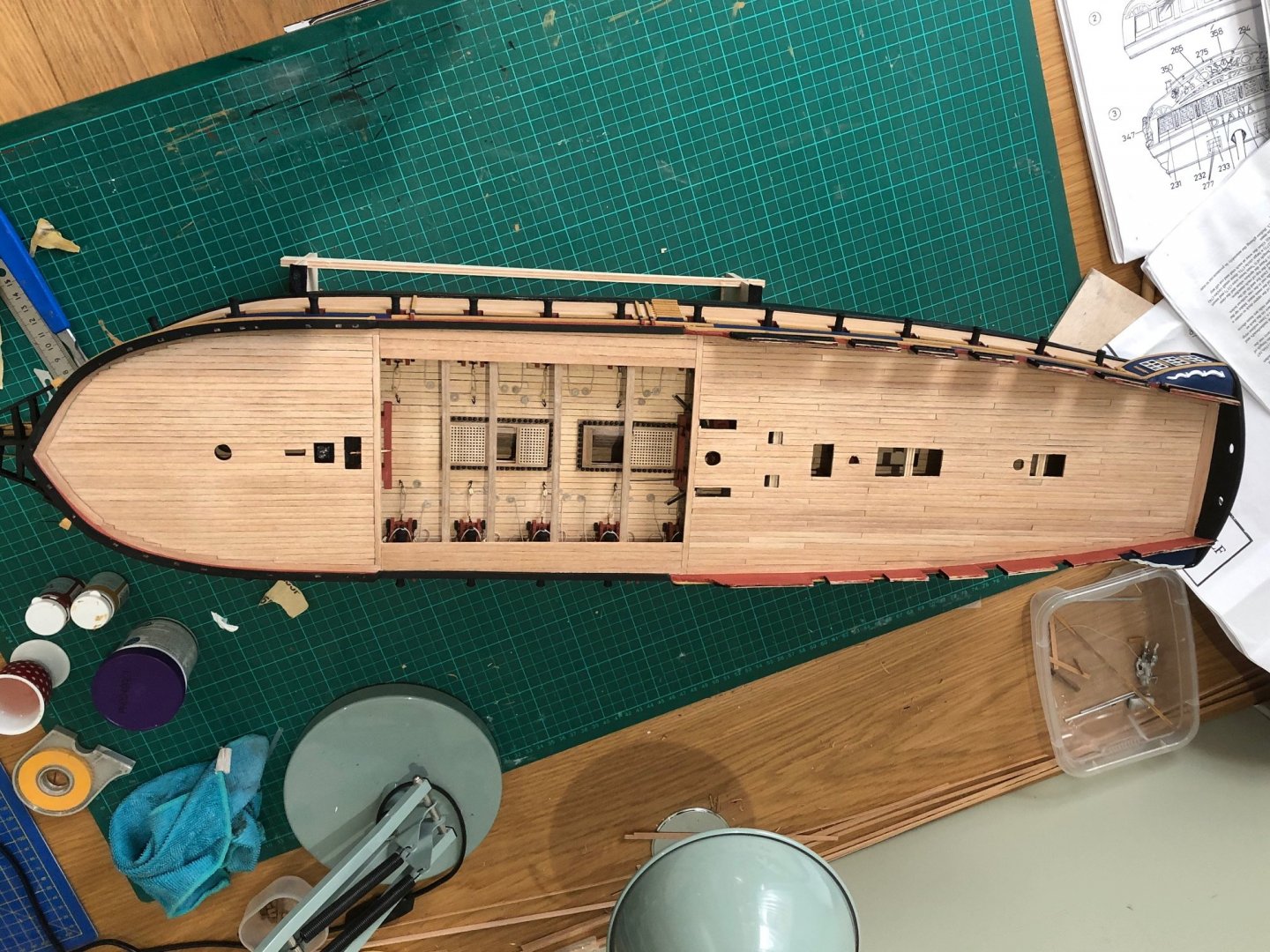
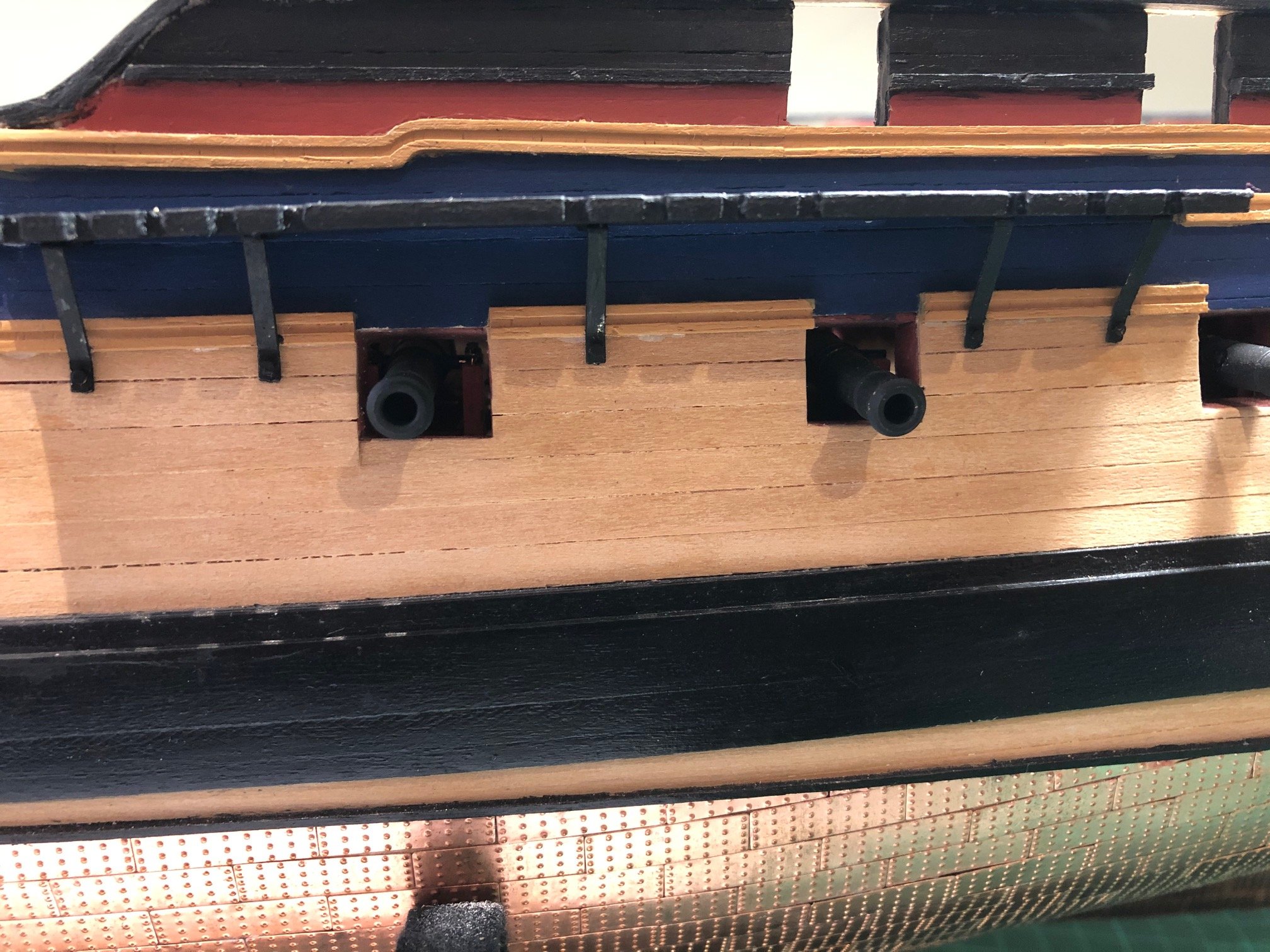
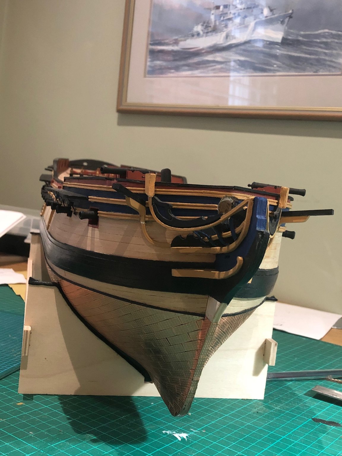
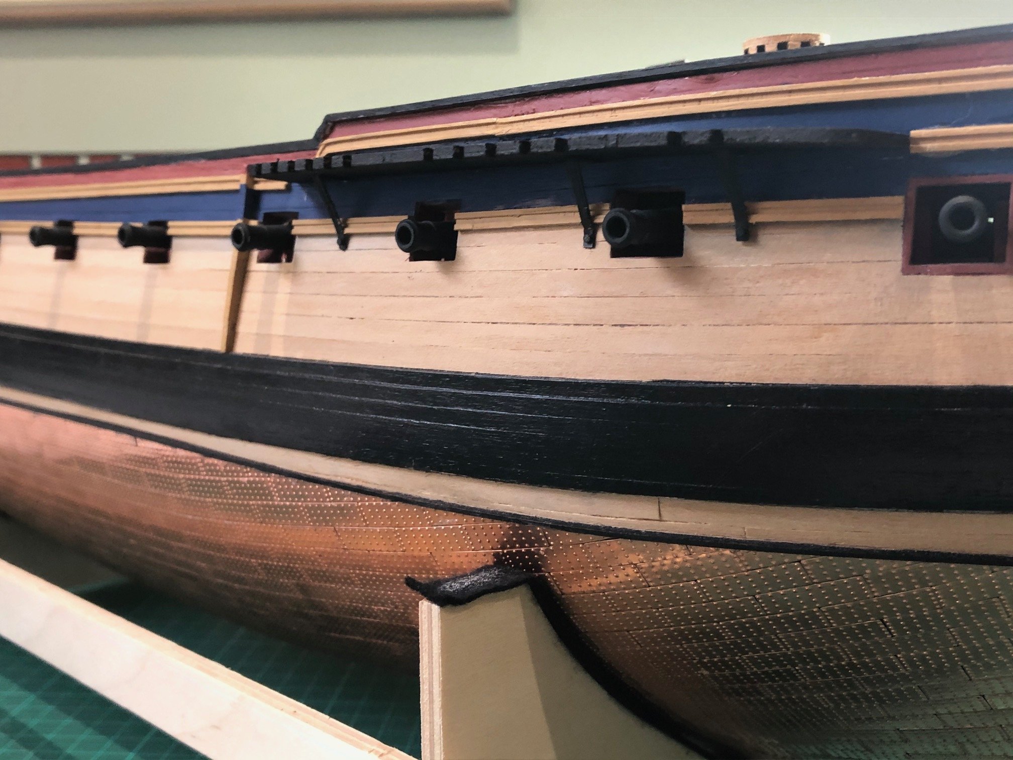
Latest update - progress hasn't been fast; despite the lockdown and working from home which I thought would wold mean more time, I am actually working harder than when in the office! Thye model has had to play second fiddle. Nevertheless, I have progressed some of the main deck fittings, the 9 pounders and I have also fitted the channels on both sides.
Not real problems with these- shortening nails, marking the channels to ensure they are clear of the gunports and chamfering the edges to ensure a tight hull fit we all fairly humdrum. Pleasingly, she is beginning to look a mature model rather than one in the early stages of build.

.thumb.jpg.a9bcf87ddf93ccaf188b94ce4b878d75.jpg)

.thumb.jpg.b4322d9092ef89a607db4e3734346af4.jpg)


-
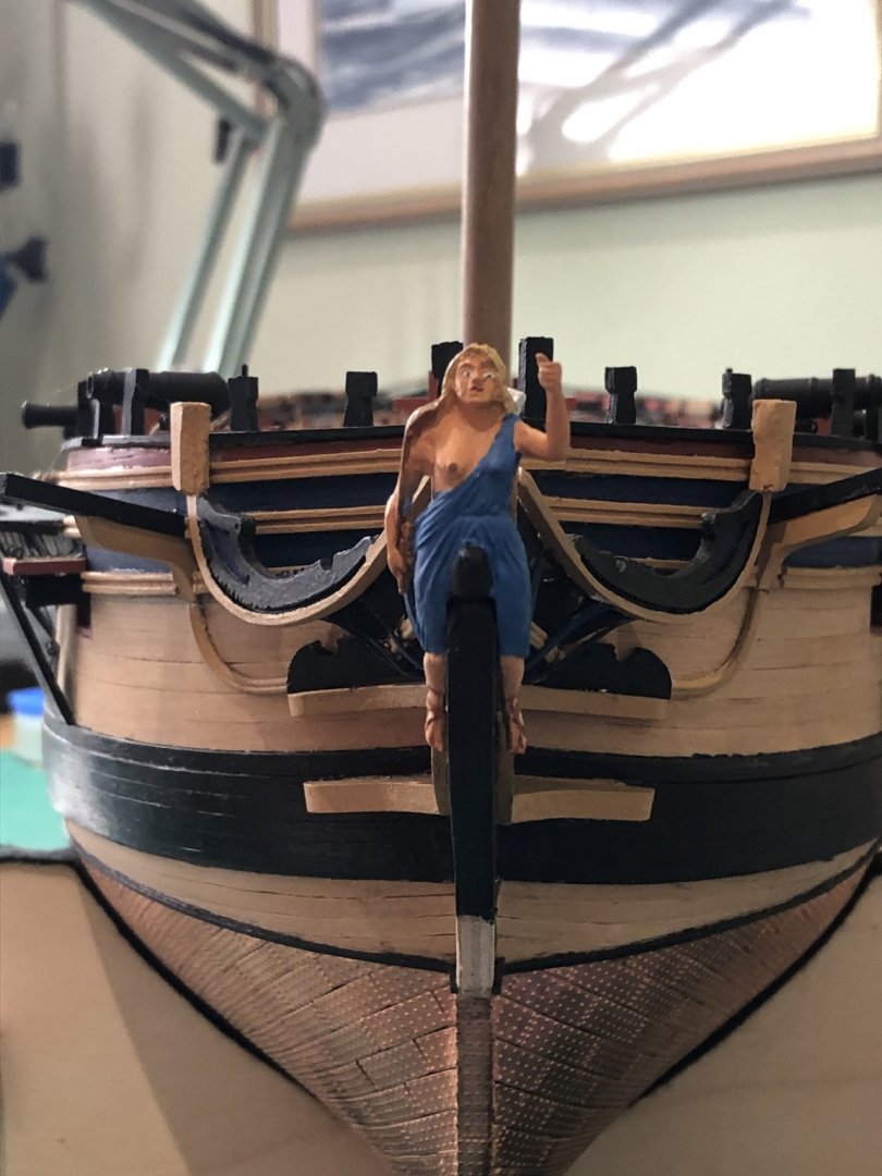
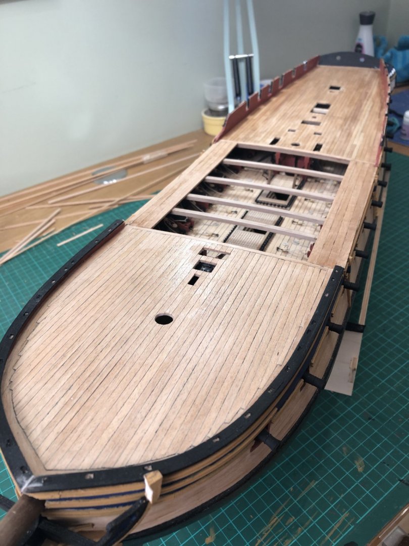
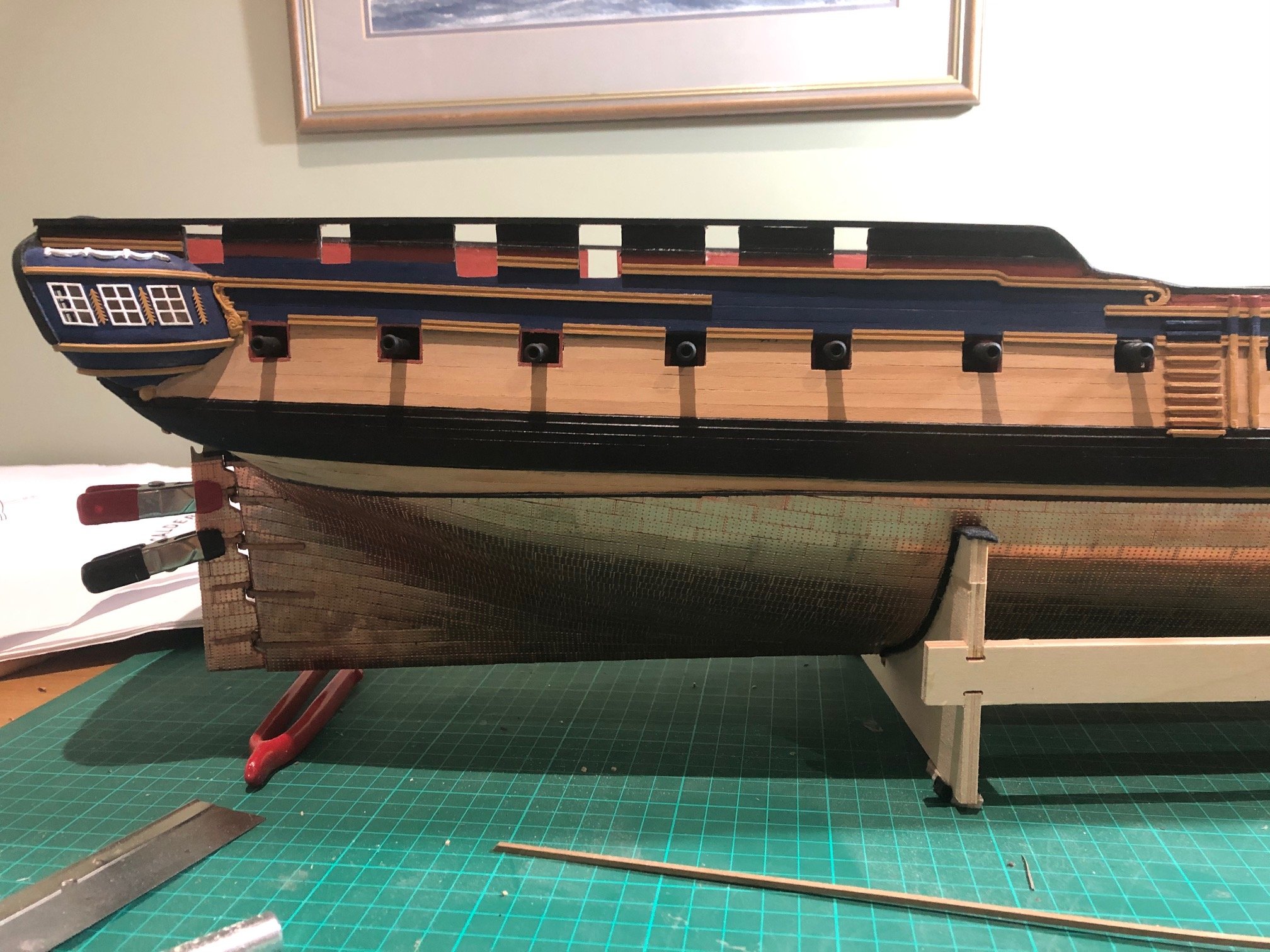
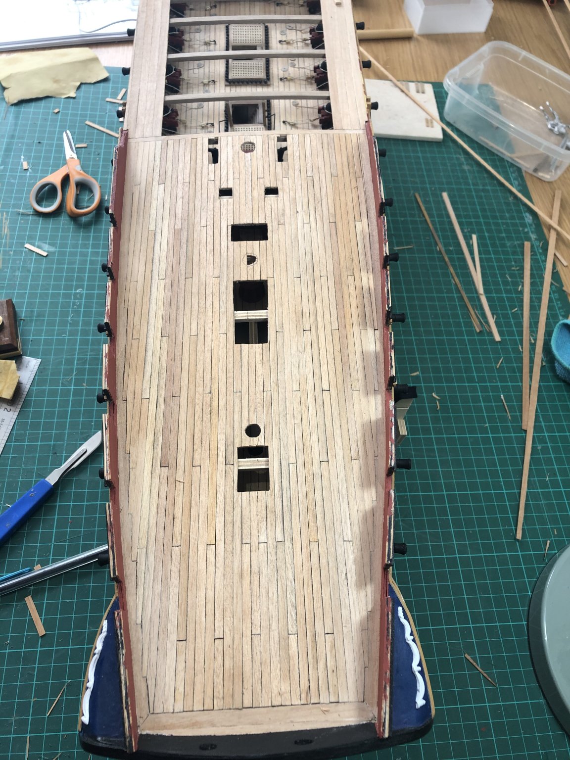
Following completion of the deck planking I completed the quarterdeck and midships capping rails out of 5x2mm beech. I am afraid the transition from ax to midships didn't look quite right so I improvised and moulded a bit of beech around the curves of the midships section. Not as per plan but for some reason my model's bulwarks seem a little low; not to worry it looks fine.
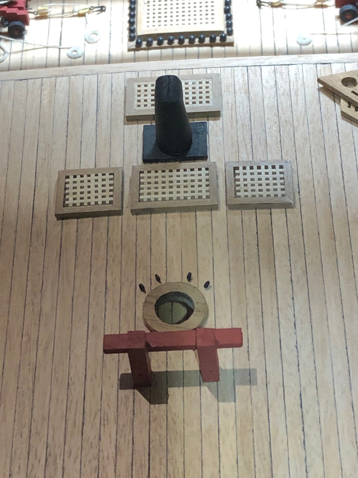
I started on the bow area. Having assembled the various pieces, effected the gluing and painting, I came to fit the various gratings and catheads. Not for nothing do the instructions highlight that building the bow is the hardest part of the model - it very much is!! I have not been able to achieve the correct levels and positioning therefore I have had to tweak the lower rail extensions to allow the hawse pipe/anchor fairleads to fit. I will attach the lower rail extension shortly and will run them from the back of the hawse fitting tot he base of the cathead: another deviation but again to the non expert eye (no comments from you lot) will be entirely acceptable.
The forecastle gratings look awkward so I am minded to follow Rob and build my own - before or after I fit the bowspit and do the gammoning....that is the question? Hmmm.
All somewhat annoying as I'm not sure where I went wrong...be careful!
I've also started on the deck furniture. Ill do a few of the guns before lookin at the hullside fittings. I would rather get all those out of the way before starting the mizzen channels and associated rigging blocks.
Onwards and upwards.
Peter


-
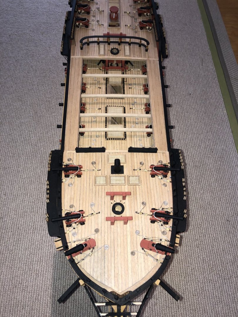
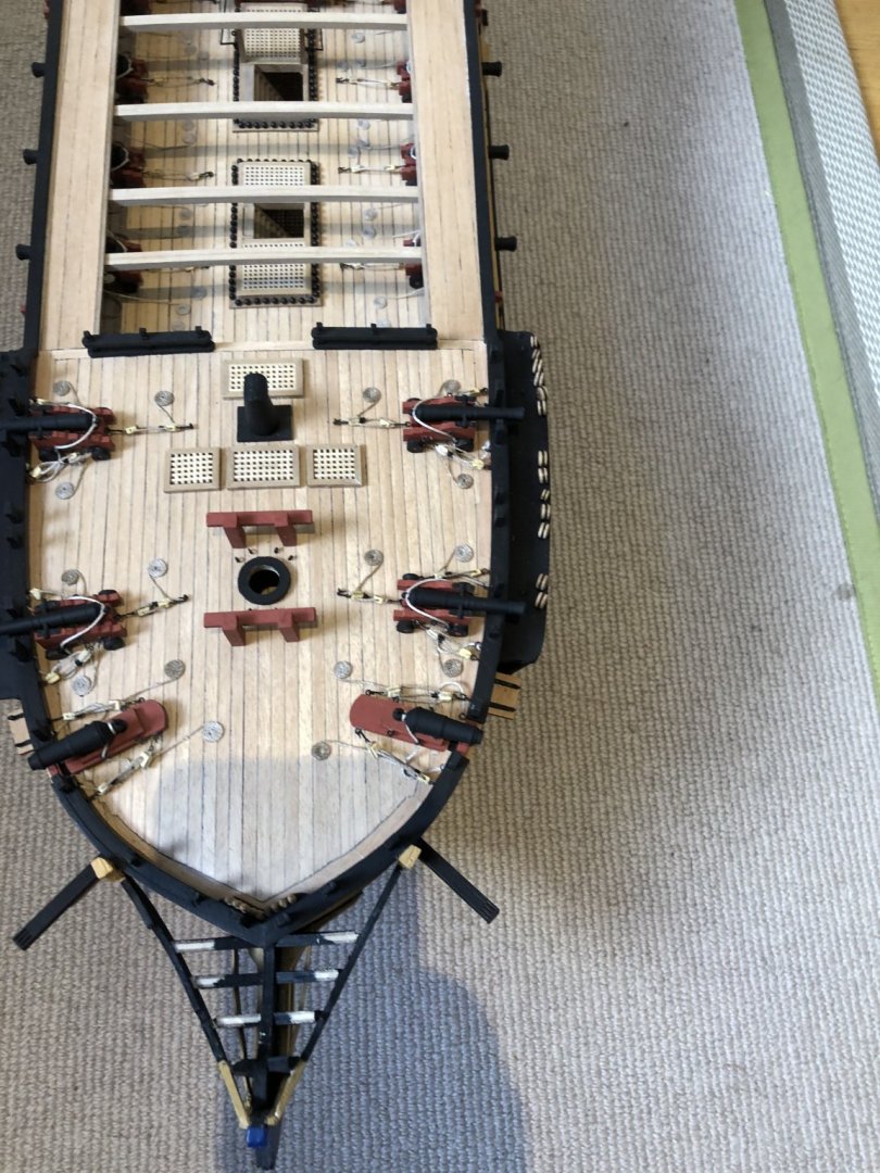
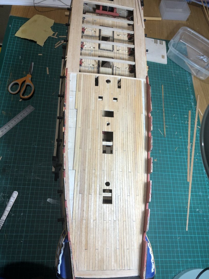
I have quietly cracked on and completed the deck planking. I managed to also achieve the nibbing (must be a made up word!) around the quarterdeck area. Sanded and varnished so good to go!

- GrandpaPhil, gieb8688, uncarina and 3 others
-
6
-
4 hours ago, Shipyard sid said:
Greetings Peter
I have just arrived back after a long while away from my build, but I honestly did not think you would have got this far on with yours. The quality of your build is honestly outstanding. I am only just finishing the second planking on mine, and off to the gun deck next as advised by Jason. Your photos of the deck will help me a lot with the work to be done on it. Yes excellent work Peter. Best advice just take your time and enjoy it. Regards DAVID.
Great to see you back. Since you posted this 'return to work' note, I have seen some of your pictures outlining some pretty rapid progress on your build - she is looking good. I now need to find your mate who was happy building gun carriages; I am about to start the building of carronades etc on the main deck and will need help! Lets not race, slow and steady - do it well! Peter
-
On 4/9/2020 at 11:53 AM, robdurant said:
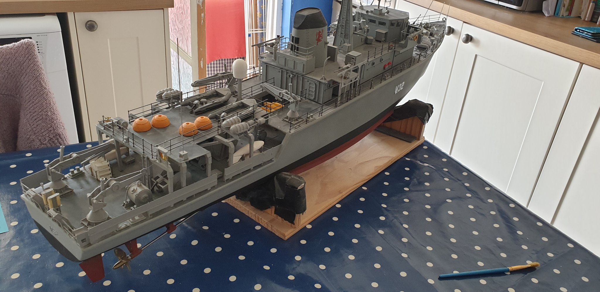
Wow - that post made me sit up... Hope you don't mind me adding a few pictures of the last (very dusty) radio controlled semi-scratch model I built... (Also HMS COTTESMORE, in 1:48). Fascinating vessels. That's a beautiful waterline model of her!
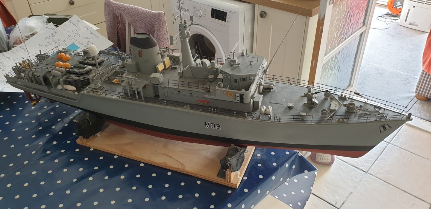

Rob
You are a modelling polymath! An RC COTTESMORE - brilliant! And in her post refit configuration … a lovely model.
- robdurant and mort stoll
-
2
-
On 4/9/2020 at 11:07 PM, Beef Wellington said:
Peter, some real eye-candy there! Great work on the decks, the nibbing looks very neat, and an inventive solution to the margin plank. Seems like you got a nice batch of Tanganika with very little grain. That's an awesome model of HMS Cottesmore as well.
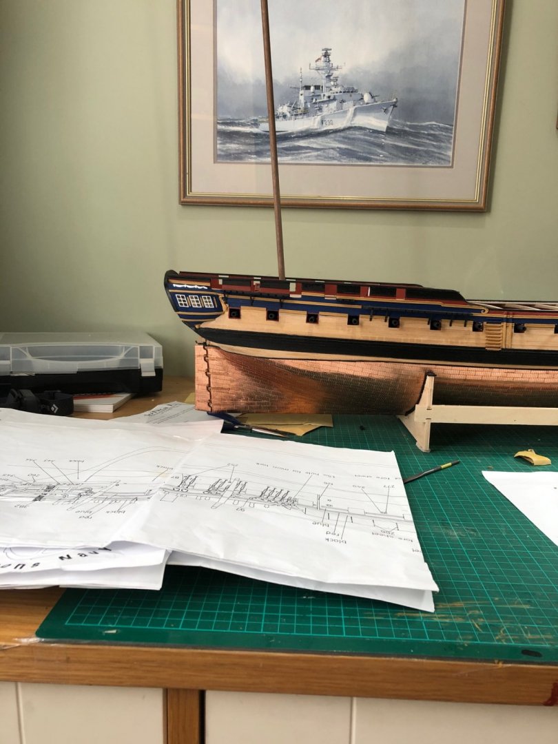
BTW - you must be very proud to have commanded such great ships, couldn't help but notice the Ton class, can't quite make out the pennant - HMS Nurton?
NURTON she is - the longest serving Ton Class in the Royal Navy; I think she did 36 years service in total. Great ship, something of the old Navy about a wooden built ship - tremendous fun although, by today's standards, not very good as a minehunter!


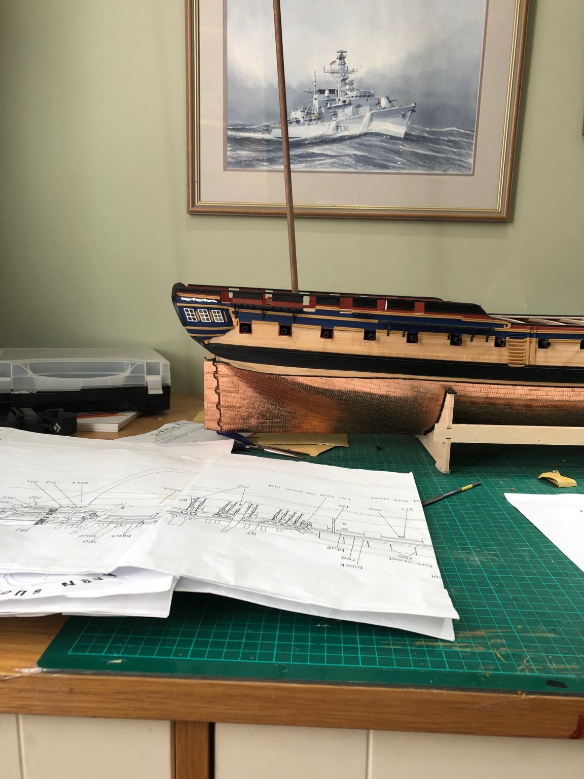


.jpg.19c6aab214d6ef6d543feb28f7af3083.jpg)
.jpg.cc44053cf1474e07b42bdb6a95281b26.jpg)


HMS DIANA by Peterhudson - Caldercraft - 1:64 Scale
in - Kit build logs for subjects built from 1751 - 1800
Posted
I attached the woolding by just seizing the line around the mast, leaving it loose to slide into position, tighten, trim ends and wash with dilute PVA. Job done.