HI
Artesania Latina was a company that began many years ago in Barcelona, after a while it moved to a town in Cantabria (province of Spain) until its disappearance.
So he seems an Andalusian businessman who has admired his products since he was a child and has bought the brand through the company EXCELLENCE MODEL KITS S.L.U in Aznalcazar, a town in the province of Seville (Spain).
At the moment the web page seems like a reconstruction of the old one, still unfinished.
Hopefully in their new journey they improve in quality and design.
In the following link there is a video of the new owner of the brand, in subtitles you can read in English
A friend gave me this wonderful little gripping tool that was made by her father when he was into model ship building many decades ago. She estimates it was probably made in the 1940s or 50s.
I have used it a few times for getting into those hard to access corners and I expect I will find it very helpful.
I have been experimenting with different ways to make deadeyes. Here I am using a 1/4" hardwood dowel in the lathe with a file to make the groove and a cutoff tool to seperate each deadeye. I have a bunch of deadeyes to make and was wondering if there is a better way to expidite the process.
The drilling of the three holes is a challenge all its own, but I have successfully made a little jig that holds the deadeye while I do the drilling. Again, it is laborious, but I don't know a better way.
Specially designed for the processing of slender masts. The base can be angled to achieve the desired taper. The dividing head can adjust the number of Polyhedra as needed, and can also be used to planing and cutting cylinder by hand.
The next step was to make the hub. I started with a .500" diameter aluminium rod. I drilled the bore on the lathe (.125") to take the prop shaft. I then mounted the rod in a square collet block and drilled cross holes (.200") to take the blade bosses.
The rod was then moved back to the lathe and the end was turned down (.400" diameter) prior to turning the spherical hub.
My ball turning tool then got one of its rare outings to turn the ball of the hub. The ball is actually symmetrical about the 4 radial holes - the camera seems to have introduced an optical illusion to move them off centre.
The ball was then parted off to the correct length (as per drawing). I next made the exit cone from brass rod - .375" machined down to .282". The rod was then mounted vertically in the mill and the 4 mounting holes were drilled axially to form the bolt holes. Then back to the lathe to machine the 45 degree cone angle before parting off. I did leave a .125" protrusion on the parted off face to locate in the axial hole in the hub. The exit cone was then pressed into the hub. The blue pencil gives some idea of scale.
The prop shaft was then superglued into the hub and then the blades were glued into the hub using 5 minute setting epoxy to give me time to set the angles. The gluing of the blades was done with the hub held in the lathe chuck and I used a piece of ply (cut at 30 degrees) to set the angles.
I then made the prop tube / boss and did a bit of s clean up and polish.
So now (unfortunately) its back to those annoying frame templates.
Hey, folks! Here's a great tip for making realistic rope coils. This post was originally made by member Peta_V in his excellent build log for Master Korabel's AVOS kit, which you can read here. Enjoy!
______________________________________________________________________________________________________________
Here is a short guide, how I do coils.
I have a jig from the scrap wood with 3 removable pins (2,3,5) and 3 securing points (1,4,6).
1. Secure the line to point 1 and make several loops around pins 2 and 3. I do 4-6 loops so the coils does not look similar. (I start with removed pin 5). Once finished with loops secure the other end to point 4.
2. Unsecure line from point 1 and pull out the very first loop through the middle of the coil.
3. Now you have to twist this to form the eye and secure it with pin 5.
4. Remove pin 2 and fully insert pin 5. Now you can adjust the coil as you want a once happy secure the end to point 6.
5. Now I secure the coil with 3 drops of CA glue. One where the eye meets coil, second ať the bottom of the coil and third to secure the loose end to the coil. Remove the coil from the jig by removing pin 5 and trim the excess thread.
6. Place the coil on the deck
Perhaps someone finds it usefull.
Stay healthy!
Peta_V
Five versions of the rectangular positioner have been designed and manufactured; the last one can be used in the plane machining of the milling machine with adjustable angles, especially the slotting of various angles of the Keel, the ribs and the crossbeam. At the same time, it can also be used as a precise positioning of rectangular assembly. The metal material can avoid the overflow of glue which makes the workpiece difficult to separate. The material is high hardness aluminum alloy (6061) and brass (H59) .
A few month ago I acquired a KKMoon K4 3W miniature desk-top laser-cutter and it has proven to be a useful investment. Therefore, I would like to share a few operational insights, though you can find a variety of ‘test’ videos and the like on the Internet.
As with many Chinese products of this kind, it comes in various guises and configurations that may be mechanically identical or not. The traders’ descriptions are often somewhat haphazard and also suffer from translation issues. I am not sure, whether KKMoon is a trader or a manufacturer, their Web-site does not actually list these laser-cutters.
Prices between the different offers on the Internet marketing platforms can vary as much as 30%. However, I paid just over 100€, shipping included.
Image of the laser-cutter as advertised
The stated main specification of the machine I bought are
- Size: about 155 mm x 166 mm x 143mm
- Weight: ca. 600 g
- Laser Power: 3 W (3000 mW) – blue = xxx nm wavelength
- Engraving Area: about 80 mm x 80 mm (3.1" x 3.1")
- Engraving Depth: about 1 mm /0.04" (Adjustable in the range of 0-1 mm)
- Mechanical resolution: 0.05 mm = 512 dpi
- Supporting System: for Windows XP / 7/8/10 and MacOS 10.10 or later
- Supporting Image Format: JPEG / JPG / PNG / BMP
- Connectivity: Micro USB B to USB A (cable included)
- Frame Material: ABS
The laser-cutting system consists of three main components that determine its capabilities: the mechanics, the control board, and the software.
Mechanics
The mechanical resolution of 512 dpi is not that brilliant, if you compare this with modern scanners or printers, but then mechanics have their price.
The 3 W diode laser has an adjustable focal point.
Control Board
I know next to nothing about electronics and commercial products, such as the control board that is being used in this machine. It would be particularly interesting to know, whether the board could be driven by other types of software. Perhaps someone from the Forum community has insights into this.
Driver
The software consists of two components, the driver and the cutting software itself. The driver is a standard piece of software under MS Windows and either comes with your MS Windows configuration or can be downloaded from the software producer’s Web-site. The driver runs under MS Windows XP/7/8/10. I am using an oldish mini-laptop with MS Windows XP on it. The driver unfortunately does not run under MS Windows emulation Parallels under MacOS 10.7.1, nor under the iOS for the iPad pro. The cutting software, however, seems to run in Parallels under MacOS 10.7.1. It should also run under MacOS 10.10 and higher, but I could not test this.
Cutting software
The cutting software is a very simple piece and is based on bit-image processing. In other words, the image is processed line by line from the top down and whenever a black pixel is encountered, the laser flashes. As noted above, the software can handle JPEG-, JPG-, PNG-, and BMP-files, but not TIFF. Images of up 1600 x 1600 pixels can be processed.
There are three variables that can be adjusted to control the cutting process: the laser power in %, the cutting depth in 0.01 mm increments, and contrast (0 to 256). It is obvious, what the power adjustment does and I assume the cutting depth is determined by the length of the laser pulse. The cutting speed cannot be adjusted explicitly. What influence the contrast setting has is not completely clear to me, as the screen appearance of the image changes, even when I use a 0/1 b/w bit image. In practice, however, it does change the width of the cutting traces.
The image to be cut can be freely moved around the cutting area of 80 mm x 80 mm on the screen.
Screenshot of the cutting software user interface
Set-up
The machine is mobile and in principle does not require any special set-up apart from a flat surface. However, any energy penetrating the material cut will be taken up by the surface on which the machine stands. This means that the material has to be fire-proof. I happened to have a piece of roof-slate at hand, which turned out to be very useful for the purpose. Pieces of marble or tiles would do as well.
The laser beam needs to be focused onto the material to be cut. The machine comes with a piece of black cardboard for the purpose, but this is thicker than many of the materials to be cut. It is better to focus the beam on the material in question. The laser spot is very bright, making it difficult to see, whether its size is minimal. I found it useful to illuminate the cutting area with a strong table lamp so that the contrast is reduced during focus setting.
The material to be cut needs to lie absolutely flat. I have been thinking of making some clamping rails or similar. It turned out that short tabs of cellotape are quite sufficient for the purpose. The small pieces of material are just taped down at each corner onto the slate.
Cutting times
I did not make systematic tests, but the examples shown here took about 10 minutes to cut. I would estimate that covering the full 80 mm x 80 mm cutting area would take in the order of about one hour.
Steering wheels cut from 0.15 mm thick Canson paper (120 g/m2) (cutting area about 40 mm x 40 mm)
Capabilities
Whether a material can be cut by laser depends on a number of properties of the material in question. First of all the material must be either combustible or it must be able to be evaporated. The material must be capable to absorb enough energy to reach its combustion point or its evaporation temperature. Whether a material can absorb enough energy depends in turn on a number of factors.
A key factor is its albedo, in other words, how well the material reflects or absorbs light. Bright and shiny materials reflect most of the light, as do white and light coloured materials. Hence they are not absorbing enough energy. Conversely, dark and in particular black materials absorb most of the light that is shot at them.
Another factor that determines how much energy is needed to combust or evaporate it is its volumetric density. Compact materials with no pores contain more mass per volume than porous materials and hence need more energy per volume to combust or evaporate. The volumetric heat conductivity is also important. If the material conducts heat well, the energy transmitted may become dissipated before it reaches the flash-point or the boiling-point.
While in theory virtually all materials could be cut with a laser, in practice the available laser may just not be powerful enough.
In practical terms this means that it is not possible to cut metal and transparent or translucent materials with this small laser. The 3 W laser just does not impart sufficient energy to melt and evaporate metals. Not surprising though. Plexiglas or tracing paper let all or too much of the light pass and therefore cannot be cut.
Bakelite paper has a high evaporation temperature and is translucent. It can be cut through in thicknesses of up to 0.1 mm, but edges become charred. A strategy can be to only cut part through and then brake off the part along the cutting. This works only for simple shapes with straight edges and not too small parts.
As set of doors (ca. 11 mm high) cut from 0.1 mm bakelite paper
White polystyrene is too reflective and is only lightly engraved, if at all. I did not have black polystyrene at hand to try this out.
I would abstain from cutting PVC due to the generation of toxic and corrosive combustion products.
I have not tried ABS or Lexan, but would expect similar issues as for polystyrene.
Celluloid might cut well, if you have a coloured variety. Transparent celluloid, including drafting films such as Ultraphane, will not work. The high flammability of celluloid may be an issue.
White paper works moderately well due to its high reflectivity. An important factor is also its weighing and seizing. Weighing with barite or titanium oxide makes it more difficult to cut, as both materials are refractory. A seizing with glue or plastic polymers increases the volumetric density and therefore make the paper more difficult to cut.
Coloured papers and cardboard work best, but thicknesses above 0.5 mm become more difficult to cut. The deeper the cut the more charring of the edges will occur, loosing precision in size and reducing the minimum size of features that can be cut.
I have not had the opportunity to cut wood, but I would expect that low-density woods cut better and then hardwoods. The size limitations are likely to be similar to those of cardboard.
Cork should cut reasonably well, but I have not tried it myself.
Drafting for cutting
As for any other ‘machining’ operation, the ‘tool’ diameter is an important consideration. The effective diameter of the well-focused laser-beam is in the order of 0.1 mm. These leads to the rounding of internal corners in this order of magnitude, but the actual rounding depends also on the size of the opening to be cut. Smaller openings may have a more perceptible rounding than larger ones.
In practice, the charring of the edges leads to slightly larger openings than those drawn. Thus the diameter of e.g. holes needs to be drawn 0.1 mm less than required. Similarly, slots should be chosen 0.1 mm narrower than the nominal width.
The laser sends a pulse for each black pixel encountered. When converting vector drawings into bit images, the question arises of the actual size of the parts that appear white in the final image to be used in the laser-cutter. This may depend on the line thickness chosen and the kind of drafting program. I found that I needed to experiment with the cutting parameters (power setting and contrast) and in some cases needed to redraft (parts of) the drawings in order to arrive at the correct size. Several iterations may be needed to arrive at the correct size. This also depends on the material, thicker material requiring more adjustments.
Every part that is black in the drawing will be burned. In order to reduce the laser time and the fumes generated, it is good practice to fill in any empty space. While this would be good practice in photo-etching too in order to safe etching fluid, often this is not done. However, when converting drawings for laser-cutting it is a good idea to fill in the empty spaces.
I use a 2D CAD system for drafting (EazyDraw™). This program allows the drawing to be exported into picture formats such as JPG. The resolution for this step has to be chosen so that the final part has the correct size for a resolution of 512 dpi or 202 pixels per centimetre. This means that a part that is 1 cm long should be 202 pixels wide in the JPG etc. file. In order to reduce the area to be burned, I usually import the image into Adobe Photoshop Elements™ and whiten all the respective areas. Sometimes is also convenient to draw the parts in solid black, which then necessitates their inversion in Photoshop. I typically export the drawings at 1024 dpi and then reduce the image in Photoshop to the desired width in the number of pixels as calculated for 512 dpi after the post-processing has been done. This allows me to ascertain that the drawing has the desired size. In this way it is also easy to produce cutting designs in various scales from the original drawing.
As the cutting happens on a flat surface and there is no mechanical interaction with the material, the cut pieces do not move from their place during the cutting process. Therefore, retaining tabs, as you would need in photo-etching, are not needed and the parts can be completely cut out. This avoids the problem of distortion during separation from the fret, particularly of very small parts.
A typical JPG-image as used for the cutting process (size around 35 mm x 30 mm)
Safety
Lasers are dangerous for the eyes and you are advised to consult the respective guidance on laser safety.
The laser-cutter comes with a green protective glass on one side. I also bought a pair of green safety-glasses for adjusting the laser focus, as viewing the focal point through the shielding glass is inconvenient.
The combustion fumes of certain materials can be a nuisance, noxious, or carcinogenic. In any case they are smelly. As noted above, it is wise to reduce the areas to be burned in order to minimise the amount of combustion products. For certain materials some kind of forced aeration may be needed, or you need to set up the laser-cutter outside.
Some materials may also be a fire hazard. However, none of the materials I worked with seem to have been problematic in this sense. There would not be enough mass to sustain a serious fire, but a fire-proof base is important.
In any case: never leave the machine running unobserved !
On the Internet you can see people, who have encased their cutters and added forced ventilation to it. Whether such arrangement is warranted, depends really on how intensively you use it. In my case it just runs occasionally for a few minutes at a time.
Conclusions
This technique cannot fully replace photo-etching to produce small, complex and delicate parts, but is is a versatile ad hoc option requiring little preparation in comparison. The cost of materials is minimal and therefore that of trial and error. There are no chemicals to manage safely, but fumes can be an issue.
There is no equivalent to the ‘surface etching’ process, parts are strictly two-dimensional. As in photo-etching, there is, however, the possibility to build up parts from several layers.
Metal surfaces and its edges can be made very smooth. Achieving the same effect with paper or cardboard is difficult, even when treated with wood-filler to produce some sort of compound material that can be sanded. In some applications that surface roughness does not matter or may be even desirable.
The mechanical resolution of 512 dpi and the diameter of 0.1 mm of the laser-beam impose limitations to the minimum size of parts that can be produced. Laser-cutting with such small desk-top machine cannot compete with commercial etching processes using high-resolution masks.
In scratch-building, when parts need to be developed as the building goes on this kind of laser-cutting certainly is a useful ad hoc and flexible process.
if you can make use of it, here is how I usualy do it. In this case the model, my Chebec Eagle of Algier, is foreseen to display in a glass cabinet when completed.
When using brass pedestals I look out for some hollow ones, for instance made from old candle holders. The connecting part is a threaded spindel, which is anchored in the ship (interlocked in a suitable threaded conterpart fastened above the keel.
The bottom side of the spindel goes through the pedestal and through the stand plate, and gets a washer and a nut as a counter part.
Please refer to the pics, trust they ars self explaining....
ALUMINIUM BONSAI WIRE
hi i love this thread , so many great ideas , i would like to recommend using 'bonsai aluminium wire , it comes already coated in dark brown and is soft enough to bend easily for deadeye strops etc and its relatively cheap and comes in many different guages i use 0.8 mm
Home made thicknessing sander if you have a lathe.
I wanted to cut some new deck planks for my Mermaid which i can do well enough,
but they would have a sawn face. So I started thinking about making a thickness sander, what did I have that spins horizontally?
The little Proxxon lathe, a little bit of thinking and came up with this item.
Its is a bit crude, just made up with bits in the shed.
The height adjustment is probably lacking in enough horizontal stability
The butt hinge is a bit loose in the pin.
And the cloth backed sandpaper is just hanging on to the velcro.
But that said, it did a pretty good job for a first up, bang it together fitting.
The lathe handled the load fine, the planks were put through against the spin.
I was only sanding a small amount each pass so holding the wood was no problem.
Certainly need refining, a dust extractor hood.
I trued up the dowel by running a file under it sitting flat on the bed.
Cheers Chris
Minor update that I thought I'd go ahead and report.
It's finally time to create a mounting display for it. I wanted something simple, given the unusual detail and shape of the model, so I went with a block-like base made from cherry wood.
This mounting will allow the model to sit high enough for me to rig the rudder and the oars, though I'll wait until I finish the last of the cabin structure details. I also discovered that there are a couple beams that don't have ties on them, so I'll finish those up next.
Most of my ship modeling delays have been because I've been trying to make/modify figures for my models. I have mostly failures, but I'm learning and working towards having maybe 3 or 4 figures for this model. I just have to double-check on the clothing from 1300 A.D. Japan.


 Belco got a reaction from Brian Hanington in The Kit-Basher's Guide To The Galaxy
 Belco reacted to Jack12477 in Tool holder that makes it easy to see the tool?
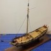 Belco got a reaction from catopower in Artesanía Latina is back!?
 Belco got a reaction from Marcus.K. in The Kit-Basher's Guide To The Galaxy
 Belco got a reaction from Jobbie in Artesanía Latina is back!?
 Belco got a reaction from Canute in Artesanía Latina is back!?
 Belco got a reaction from mtaylor in Artesanía Latina is back!?