


Beef Wellington
-
Posts
2,245 -
Joined
-
Last visited
Reputation Activity
-

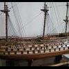
 Beef Wellington reacted to Kevin in HMS Jason by Beef Wellington - Caldercraft - 1:64 - Artois-class frigate modified from HMS Diana 1794
Jason that is absolutely stunning work
-

 Beef Wellington got a reaction from scrubbyj427 in HMS Jason by Beef Wellington - Caldercraft - 1:64 - Artois-class frigate modified from HMS Diana 1794
Headworks (Part 1):
The shipyard has not been very active recently, partly due to lack of time, but also trepidation of the fact that I can no longer delay work on the headworks - something that has caused some anxiety if I'm honest given that this is another aspect of the model that is so important to the overall look of the ship (...and especially considering that the TFFM devotes 17 pages to this!). I had completed the main rail back in 2018 (Yikes!) which are detailed here (Post #513) for reference.
I tried to follow the guidance and approach described in the TFFM as this will all need to be scratch to replicate the original plans as closely as possible, but did probably simplify some steps. With the final profile of the bow having been finalized, the position of these can be determined. This was done by eye in the absence of any definitive measurement, ensuring that the head of the mainrail is perpendicular to the keel and vertical when viewed from the bow. These were drilled and pinned to hold in position for now. Together with the standard, the 4 head timbers were rough cut and sized to their respective position, the outer face being cut to the angle formed by the head rail. The curvature of the head timbers was estimated from the AOTS diagrams, but left a little oversized at this stage (the interior profile has also been ignored for the present and will be cut to final shape later). The main consideration was to ensure that the position of the bottom of the main rail was determined, and this was done by multiple fine tunings and a sanding stick.
The position and fitting of the lower rail proved to be the more challenging aspect. The TFFM indicates that it should be straight when viewed from above, and the plan profiles suggest that it should be position midway between the main rail and the upper cheek.. On top of that, it needs to clear the interior hawse hole, and will also need to taper in profile at the bow. The seats of ease on the Artois class are outboard, and will also clear the lower rail. I do not know the thickness of this piece, but estimated it should be 2mm thick which seems consistent with the proportions shown and described in TFFM for the Swan class.
I started by drawing my own simple scale mini-plan using the measurements of the hawse hole, position of head timbers and length of the lower rail. This allowed the depth of the slots to be determined on each head timber, at the point mid way between the bottom of the main rail and top of the upper cheek (This will also determine the required final curvature of the head timbers to ensure that the lower rail sits neatly behind the covering boards which will need to be added in the future,
Once these had been roughly determined and cut into the head timbers, the theory and application was proved using some of the kit supplied white metal decorative strips which are very easily bent. (The kit indicates that these should actually be used for the lower rail which seems to be a very reasonable compromise, but think Jason deserves to appropriately proportioned and profiled wood rail). The curvature of this metal rail can then be used to determine the curvature of the top of the lower rail that will be cut from wood. (Note: The forward head timber has been ignored for now, I will need to recut this piece so it extends higher over the standard, as it is, its not think enough to accommodate the lower rail). The white metal strip is also very useful because it allows the length of the lower rail to be determined.
A cut first approximation of the lower rail was then cut from some boxwood sheet and temporarily placed in position to again prove the approach. This proved to be successful, and I was happy with the general profile that resulted. This looks overly bulky to my eye even though the dimension are appropriate, but I suspect that this will be corrected once it has been profiled. The next step will be to cut and profile the actual pieces. This also shows that I will likely need to adjust the hawse bolster to allow the lower rail, and the yet to be fitted eking rail (see last picture, the lower rail does not clear the top of the bolster. Even though there is still much to do in this area, I'm feeling more optimistic with this complex area.
-
 Beef Wellington got a reaction from allanyed in HMS Jason by Beef Wellington - Caldercraft - 1:64 - Artois-class frigate modified from HMS Diana 1794
Headworks (Part 1):
The shipyard has not been very active recently, partly due to lack of time, but also trepidation of the fact that I can no longer delay work on the headworks - something that has caused some anxiety if I'm honest given that this is another aspect of the model that is so important to the overall look of the ship (...and especially considering that the TFFM devotes 17 pages to this!). I had completed the main rail back in 2018 (Yikes!) which are detailed here (Post #513) for reference.
I tried to follow the guidance and approach described in the TFFM as this will all need to be scratch to replicate the original plans as closely as possible, but did probably simplify some steps. With the final profile of the bow having been finalized, the position of these can be determined. This was done by eye in the absence of any definitive measurement, ensuring that the head of the mainrail is perpendicular to the keel and vertical when viewed from the bow. These were drilled and pinned to hold in position for now. Together with the standard, the 4 head timbers were rough cut and sized to their respective position, the outer face being cut to the angle formed by the head rail. The curvature of the head timbers was estimated from the AOTS diagrams, but left a little oversized at this stage (the interior profile has also been ignored for the present and will be cut to final shape later). The main consideration was to ensure that the position of the bottom of the main rail was determined, and this was done by multiple fine tunings and a sanding stick.
The position and fitting of the lower rail proved to be the more challenging aspect. The TFFM indicates that it should be straight when viewed from above, and the plan profiles suggest that it should be position midway between the main rail and the upper cheek.. On top of that, it needs to clear the interior hawse hole, and will also need to taper in profile at the bow. The seats of ease on the Artois class are outboard, and will also clear the lower rail. I do not know the thickness of this piece, but estimated it should be 2mm thick which seems consistent with the proportions shown and described in TFFM for the Swan class.
I started by drawing my own simple scale mini-plan using the measurements of the hawse hole, position of head timbers and length of the lower rail. This allowed the depth of the slots to be determined on each head timber, at the point mid way between the bottom of the main rail and top of the upper cheek (This will also determine the required final curvature of the head timbers to ensure that the lower rail sits neatly behind the covering boards which will need to be added in the future,
Once these had been roughly determined and cut into the head timbers, the theory and application was proved using some of the kit supplied white metal decorative strips which are very easily bent. (The kit indicates that these should actually be used for the lower rail which seems to be a very reasonable compromise, but think Jason deserves to appropriately proportioned and profiled wood rail). The curvature of this metal rail can then be used to determine the curvature of the top of the lower rail that will be cut from wood. (Note: The forward head timber has been ignored for now, I will need to recut this piece so it extends higher over the standard, as it is, its not think enough to accommodate the lower rail). The white metal strip is also very useful because it allows the length of the lower rail to be determined.
A cut first approximation of the lower rail was then cut from some boxwood sheet and temporarily placed in position to again prove the approach. This proved to be successful, and I was happy with the general profile that resulted. This looks overly bulky to my eye even though the dimension are appropriate, but I suspect that this will be corrected once it has been profiled. The next step will be to cut and profile the actual pieces. This also shows that I will likely need to adjust the hawse bolster to allow the lower rail, and the yet to be fitted eking rail (see last picture, the lower rail does not clear the top of the bolster. Even though there is still much to do in this area, I'm feeling more optimistic with this complex area.
-
Beef Wellington reacted to Kevin in HMS Indefatigable 1794 by Kevin - Vanguard Models - 1:64 - Feb 2023
i used frames 4 to 14
so on attached photo working forward F- Frame number in MM
tuck to F13 about 200
F13 to F9 220
F9 to F5 220
F5 to bow 195
-
Beef Wellington reacted to Blue Ensign in HMS Indefatigable 1794 by Blue Ensign - FINISHED - Vanguard Models - 1:64 scale
Post Twenty-four
At this point I skip sections 165-191 and move to fit the keel, stem, and sternpost pieces.
I want the keel pieces in place to modify the build board for the upright hull which will be used for most of the fitting out and detailing.
All these pieces fit together nicely.
Note: The keel facings are numbered 437/439 (Fore) and 438/440 (stern) – not as shown in the manual. The pieces are port and starboard specific.
0832
I found the trickiest part was fitting the stem facings. I needed to further tweak the planks ends using a micro chisel to allow the facing pieces to sit flat against the stem at all points, and line up with the peg slots.
The hull will remain inverted for hull planking and that board has been modified to protect the vulnerable stem piece.
0833
0835
The stem protectors can be swung in and out of position.
It would be a tricky issue if the delicate figure seating at the prow was to be broken off.
0840
0841
The upright building board has now been modified to support the planked hull.
0842
0838
Indy is now secure and sitting level, I don’t want this beast moving around whilst I am working on her.
On with the show.
B.E.
19/04/2023
-
Beef Wellington reacted to Blue Ensign in HMS Indefatigable 1794 by Blue Ensign - FINISHED - Vanguard Models - 1:64 scale
I'm not prepared to risk it Jason, it also has implications for the keel.
Knowing when not to meddle is a valuable skill in our business.😉
Cheers,
B.E.
-
 Beef Wellington got a reaction from bruce d in HMS Jason by Beef Wellington - Caldercraft - 1:64 - Artois-class frigate modified from HMS Diana 1794
Headworks (Part 1):
The shipyard has not been very active recently, partly due to lack of time, but also trepidation of the fact that I can no longer delay work on the headworks - something that has caused some anxiety if I'm honest given that this is another aspect of the model that is so important to the overall look of the ship (...and especially considering that the TFFM devotes 17 pages to this!). I had completed the main rail back in 2018 (Yikes!) which are detailed here (Post #513) for reference.
I tried to follow the guidance and approach described in the TFFM as this will all need to be scratch to replicate the original plans as closely as possible, but did probably simplify some steps. With the final profile of the bow having been finalized, the position of these can be determined. This was done by eye in the absence of any definitive measurement, ensuring that the head of the mainrail is perpendicular to the keel and vertical when viewed from the bow. These were drilled and pinned to hold in position for now. Together with the standard, the 4 head timbers were rough cut and sized to their respective position, the outer face being cut to the angle formed by the head rail. The curvature of the head timbers was estimated from the AOTS diagrams, but left a little oversized at this stage (the interior profile has also been ignored for the present and will be cut to final shape later). The main consideration was to ensure that the position of the bottom of the main rail was determined, and this was done by multiple fine tunings and a sanding stick.
The position and fitting of the lower rail proved to be the more challenging aspect. The TFFM indicates that it should be straight when viewed from above, and the plan profiles suggest that it should be position midway between the main rail and the upper cheek.. On top of that, it needs to clear the interior hawse hole, and will also need to taper in profile at the bow. The seats of ease on the Artois class are outboard, and will also clear the lower rail. I do not know the thickness of this piece, but estimated it should be 2mm thick which seems consistent with the proportions shown and described in TFFM for the Swan class.
I started by drawing my own simple scale mini-plan using the measurements of the hawse hole, position of head timbers and length of the lower rail. This allowed the depth of the slots to be determined on each head timber, at the point mid way between the bottom of the main rail and top of the upper cheek (This will also determine the required final curvature of the head timbers to ensure that the lower rail sits neatly behind the covering boards which will need to be added in the future,
Once these had been roughly determined and cut into the head timbers, the theory and application was proved using some of the kit supplied white metal decorative strips which are very easily bent. (The kit indicates that these should actually be used for the lower rail which seems to be a very reasonable compromise, but think Jason deserves to appropriately proportioned and profiled wood rail). The curvature of this metal rail can then be used to determine the curvature of the top of the lower rail that will be cut from wood. (Note: The forward head timber has been ignored for now, I will need to recut this piece so it extends higher over the standard, as it is, its not think enough to accommodate the lower rail). The white metal strip is also very useful because it allows the length of the lower rail to be determined.
A cut first approximation of the lower rail was then cut from some boxwood sheet and temporarily placed in position to again prove the approach. This proved to be successful, and I was happy with the general profile that resulted. This looks overly bulky to my eye even though the dimension are appropriate, but I suspect that this will be corrected once it has been profiled. The next step will be to cut and profile the actual pieces. This also shows that I will likely need to adjust the hawse bolster to allow the lower rail, and the yet to be fitted eking rail (see last picture, the lower rail does not clear the top of the bolster. Even though there is still much to do in this area, I'm feeling more optimistic with this complex area.
-
 Beef Wellington got a reaction from Barbossa in HMS Jason by Beef Wellington - Caldercraft - 1:64 - Artois-class frigate modified from HMS Diana 1794
Headworks (Part 1):
The shipyard has not been very active recently, partly due to lack of time, but also trepidation of the fact that I can no longer delay work on the headworks - something that has caused some anxiety if I'm honest given that this is another aspect of the model that is so important to the overall look of the ship (...and especially considering that the TFFM devotes 17 pages to this!). I had completed the main rail back in 2018 (Yikes!) which are detailed here (Post #513) for reference.
I tried to follow the guidance and approach described in the TFFM as this will all need to be scratch to replicate the original plans as closely as possible, but did probably simplify some steps. With the final profile of the bow having been finalized, the position of these can be determined. This was done by eye in the absence of any definitive measurement, ensuring that the head of the mainrail is perpendicular to the keel and vertical when viewed from the bow. These were drilled and pinned to hold in position for now. Together with the standard, the 4 head timbers were rough cut and sized to their respective position, the outer face being cut to the angle formed by the head rail. The curvature of the head timbers was estimated from the AOTS diagrams, but left a little oversized at this stage (the interior profile has also been ignored for the present and will be cut to final shape later). The main consideration was to ensure that the position of the bottom of the main rail was determined, and this was done by multiple fine tunings and a sanding stick.
The position and fitting of the lower rail proved to be the more challenging aspect. The TFFM indicates that it should be straight when viewed from above, and the plan profiles suggest that it should be position midway between the main rail and the upper cheek.. On top of that, it needs to clear the interior hawse hole, and will also need to taper in profile at the bow. The seats of ease on the Artois class are outboard, and will also clear the lower rail. I do not know the thickness of this piece, but estimated it should be 2mm thick which seems consistent with the proportions shown and described in TFFM for the Swan class.
I started by drawing my own simple scale mini-plan using the measurements of the hawse hole, position of head timbers and length of the lower rail. This allowed the depth of the slots to be determined on each head timber, at the point mid way between the bottom of the main rail and top of the upper cheek (This will also determine the required final curvature of the head timbers to ensure that the lower rail sits neatly behind the covering boards which will need to be added in the future,
Once these had been roughly determined and cut into the head timbers, the theory and application was proved using some of the kit supplied white metal decorative strips which are very easily bent. (The kit indicates that these should actually be used for the lower rail which seems to be a very reasonable compromise, but think Jason deserves to appropriately proportioned and profiled wood rail). The curvature of this metal rail can then be used to determine the curvature of the top of the lower rail that will be cut from wood. (Note: The forward head timber has been ignored for now, I will need to recut this piece so it extends higher over the standard, as it is, its not think enough to accommodate the lower rail). The white metal strip is also very useful because it allows the length of the lower rail to be determined.
A cut first approximation of the lower rail was then cut from some boxwood sheet and temporarily placed in position to again prove the approach. This proved to be successful, and I was happy with the general profile that resulted. This looks overly bulky to my eye even though the dimension are appropriate, but I suspect that this will be corrected once it has been profiled. The next step will be to cut and profile the actual pieces. This also shows that I will likely need to adjust the hawse bolster to allow the lower rail, and the yet to be fitted eking rail (see last picture, the lower rail does not clear the top of the bolster. Even though there is still much to do in this area, I'm feeling more optimistic with this complex area.
-
 Beef Wellington got a reaction from BLACK VIKING in HMS Jason by Beef Wellington - Caldercraft - 1:64 - Artois-class frigate modified from HMS Diana 1794
Headworks (Part 1):
The shipyard has not been very active recently, partly due to lack of time, but also trepidation of the fact that I can no longer delay work on the headworks - something that has caused some anxiety if I'm honest given that this is another aspect of the model that is so important to the overall look of the ship (...and especially considering that the TFFM devotes 17 pages to this!). I had completed the main rail back in 2018 (Yikes!) which are detailed here (Post #513) for reference.
I tried to follow the guidance and approach described in the TFFM as this will all need to be scratch to replicate the original plans as closely as possible, but did probably simplify some steps. With the final profile of the bow having been finalized, the position of these can be determined. This was done by eye in the absence of any definitive measurement, ensuring that the head of the mainrail is perpendicular to the keel and vertical when viewed from the bow. These were drilled and pinned to hold in position for now. Together with the standard, the 4 head timbers were rough cut and sized to their respective position, the outer face being cut to the angle formed by the head rail. The curvature of the head timbers was estimated from the AOTS diagrams, but left a little oversized at this stage (the interior profile has also been ignored for the present and will be cut to final shape later). The main consideration was to ensure that the position of the bottom of the main rail was determined, and this was done by multiple fine tunings and a sanding stick.
The position and fitting of the lower rail proved to be the more challenging aspect. The TFFM indicates that it should be straight when viewed from above, and the plan profiles suggest that it should be position midway between the main rail and the upper cheek.. On top of that, it needs to clear the interior hawse hole, and will also need to taper in profile at the bow. The seats of ease on the Artois class are outboard, and will also clear the lower rail. I do not know the thickness of this piece, but estimated it should be 2mm thick which seems consistent with the proportions shown and described in TFFM for the Swan class.
I started by drawing my own simple scale mini-plan using the measurements of the hawse hole, position of head timbers and length of the lower rail. This allowed the depth of the slots to be determined on each head timber, at the point mid way between the bottom of the main rail and top of the upper cheek (This will also determine the required final curvature of the head timbers to ensure that the lower rail sits neatly behind the covering boards which will need to be added in the future,
Once these had been roughly determined and cut into the head timbers, the theory and application was proved using some of the kit supplied white metal decorative strips which are very easily bent. (The kit indicates that these should actually be used for the lower rail which seems to be a very reasonable compromise, but think Jason deserves to appropriately proportioned and profiled wood rail). The curvature of this metal rail can then be used to determine the curvature of the top of the lower rail that will be cut from wood. (Note: The forward head timber has been ignored for now, I will need to recut this piece so it extends higher over the standard, as it is, its not think enough to accommodate the lower rail). The white metal strip is also very useful because it allows the length of the lower rail to be determined.
A cut first approximation of the lower rail was then cut from some boxwood sheet and temporarily placed in position to again prove the approach. This proved to be successful, and I was happy with the general profile that resulted. This looks overly bulky to my eye even though the dimension are appropriate, but I suspect that this will be corrected once it has been profiled. The next step will be to cut and profile the actual pieces. This also shows that I will likely need to adjust the hawse bolster to allow the lower rail, and the yet to be fitted eking rail (see last picture, the lower rail does not clear the top of the bolster. Even though there is still much to do in this area, I'm feeling more optimistic with this complex area.
-
 Beef Wellington got a reaction from JpR62 in HMS Jason by Beef Wellington - Caldercraft - 1:64 - Artois-class frigate modified from HMS Diana 1794
Headworks (Part 1):
The shipyard has not been very active recently, partly due to lack of time, but also trepidation of the fact that I can no longer delay work on the headworks - something that has caused some anxiety if I'm honest given that this is another aspect of the model that is so important to the overall look of the ship (...and especially considering that the TFFM devotes 17 pages to this!). I had completed the main rail back in 2018 (Yikes!) which are detailed here (Post #513) for reference.
I tried to follow the guidance and approach described in the TFFM as this will all need to be scratch to replicate the original plans as closely as possible, but did probably simplify some steps. With the final profile of the bow having been finalized, the position of these can be determined. This was done by eye in the absence of any definitive measurement, ensuring that the head of the mainrail is perpendicular to the keel and vertical when viewed from the bow. These were drilled and pinned to hold in position for now. Together with the standard, the 4 head timbers were rough cut and sized to their respective position, the outer face being cut to the angle formed by the head rail. The curvature of the head timbers was estimated from the AOTS diagrams, but left a little oversized at this stage (the interior profile has also been ignored for the present and will be cut to final shape later). The main consideration was to ensure that the position of the bottom of the main rail was determined, and this was done by multiple fine tunings and a sanding stick.
The position and fitting of the lower rail proved to be the more challenging aspect. The TFFM indicates that it should be straight when viewed from above, and the plan profiles suggest that it should be position midway between the main rail and the upper cheek.. On top of that, it needs to clear the interior hawse hole, and will also need to taper in profile at the bow. The seats of ease on the Artois class are outboard, and will also clear the lower rail. I do not know the thickness of this piece, but estimated it should be 2mm thick which seems consistent with the proportions shown and described in TFFM for the Swan class.
I started by drawing my own simple scale mini-plan using the measurements of the hawse hole, position of head timbers and length of the lower rail. This allowed the depth of the slots to be determined on each head timber, at the point mid way between the bottom of the main rail and top of the upper cheek (This will also determine the required final curvature of the head timbers to ensure that the lower rail sits neatly behind the covering boards which will need to be added in the future,
Once these had been roughly determined and cut into the head timbers, the theory and application was proved using some of the kit supplied white metal decorative strips which are very easily bent. (The kit indicates that these should actually be used for the lower rail which seems to be a very reasonable compromise, but think Jason deserves to appropriately proportioned and profiled wood rail). The curvature of this metal rail can then be used to determine the curvature of the top of the lower rail that will be cut from wood. (Note: The forward head timber has been ignored for now, I will need to recut this piece so it extends higher over the standard, as it is, its not think enough to accommodate the lower rail). The white metal strip is also very useful because it allows the length of the lower rail to be determined.
A cut first approximation of the lower rail was then cut from some boxwood sheet and temporarily placed in position to again prove the approach. This proved to be successful, and I was happy with the general profile that resulted. This looks overly bulky to my eye even though the dimension are appropriate, but I suspect that this will be corrected once it has been profiled. The next step will be to cut and profile the actual pieces. This also shows that I will likely need to adjust the hawse bolster to allow the lower rail, and the yet to be fitted eking rail (see last picture, the lower rail does not clear the top of the bolster. Even though there is still much to do in this area, I'm feeling more optimistic with this complex area.
-
Beef Wellington got a reaction from allanyed in HMS Indefatigable 1794 by Blue Ensign - FINISHED - Vanguard Models - 1:64 scale
Looking very good as always. Nice feature to have the stem fascia create the rabbet. Are you going to taper the stem, or will that mess up the figurehead fitting? Looks like the main stem piece could be tapered before attaching the facings.
-
 Beef Wellington got a reaction from Javelin in HMS Jason by Beef Wellington - Caldercraft - 1:64 - Artois-class frigate modified from HMS Diana 1794
Headworks (Part 1):
The shipyard has not been very active recently, partly due to lack of time, but also trepidation of the fact that I can no longer delay work on the headworks - something that has caused some anxiety if I'm honest given that this is another aspect of the model that is so important to the overall look of the ship (...and especially considering that the TFFM devotes 17 pages to this!). I had completed the main rail back in 2018 (Yikes!) which are detailed here (Post #513) for reference.
I tried to follow the guidance and approach described in the TFFM as this will all need to be scratch to replicate the original plans as closely as possible, but did probably simplify some steps. With the final profile of the bow having been finalized, the position of these can be determined. This was done by eye in the absence of any definitive measurement, ensuring that the head of the mainrail is perpendicular to the keel and vertical when viewed from the bow. These were drilled and pinned to hold in position for now. Together with the standard, the 4 head timbers were rough cut and sized to their respective position, the outer face being cut to the angle formed by the head rail. The curvature of the head timbers was estimated from the AOTS diagrams, but left a little oversized at this stage (the interior profile has also been ignored for the present and will be cut to final shape later). The main consideration was to ensure that the position of the bottom of the main rail was determined, and this was done by multiple fine tunings and a sanding stick.
The position and fitting of the lower rail proved to be the more challenging aspect. The TFFM indicates that it should be straight when viewed from above, and the plan profiles suggest that it should be position midway between the main rail and the upper cheek.. On top of that, it needs to clear the interior hawse hole, and will also need to taper in profile at the bow. The seats of ease on the Artois class are outboard, and will also clear the lower rail. I do not know the thickness of this piece, but estimated it should be 2mm thick which seems consistent with the proportions shown and described in TFFM for the Swan class.
I started by drawing my own simple scale mini-plan using the measurements of the hawse hole, position of head timbers and length of the lower rail. This allowed the depth of the slots to be determined on each head timber, at the point mid way between the bottom of the main rail and top of the upper cheek (This will also determine the required final curvature of the head timbers to ensure that the lower rail sits neatly behind the covering boards which will need to be added in the future,
Once these had been roughly determined and cut into the head timbers, the theory and application was proved using some of the kit supplied white metal decorative strips which are very easily bent. (The kit indicates that these should actually be used for the lower rail which seems to be a very reasonable compromise, but think Jason deserves to appropriately proportioned and profiled wood rail). The curvature of this metal rail can then be used to determine the curvature of the top of the lower rail that will be cut from wood. (Note: The forward head timber has been ignored for now, I will need to recut this piece so it extends higher over the standard, as it is, its not think enough to accommodate the lower rail). The white metal strip is also very useful because it allows the length of the lower rail to be determined.
A cut first approximation of the lower rail was then cut from some boxwood sheet and temporarily placed in position to again prove the approach. This proved to be successful, and I was happy with the general profile that resulted. This looks overly bulky to my eye even though the dimension are appropriate, but I suspect that this will be corrected once it has been profiled. The next step will be to cut and profile the actual pieces. This also shows that I will likely need to adjust the hawse bolster to allow the lower rail, and the yet to be fitted eking rail (see last picture, the lower rail does not clear the top of the bolster. Even though there is still much to do in this area, I'm feeling more optimistic with this complex area.
-
Beef Wellington got a reaction from bruce d in HMS Jason by Beef Wellington - Caldercraft - 1:64 - Artois-class frigate modified from HMS Diana 1794
Final shaping of the hull, installation of tafferal and plansheer:
Happy New Year everyone! Lots of work over the holidays has finally resulted in what I consider to be a major milestone, namely the final shaping of the hull, installation of tafferal and plansheer. Before I could proceed, had to finally deal with some cannon dislocations that I had been putting off for a while - two of the rear cannons has become loose, the carriages were still firmly fixed luckily, but the barrels had broken away. Thank goodness for those long thin CA tubes that allowed these to be re-glued through the gunport...panic over.
Once the volutes had been installed and the gunports were cut out and finished (photos below show the aft and fore positioning), it was possible to install the remainder of the quarterdeck drift which was installed parallel to the main wale. This then allowed the final shape of the upper hull to be determined, once again parallel to the main wale. The topside of the bulwarks should be horizontal, and I found that the easiest way to do this was to use a long enough file that would reach from one side to the other, fine tuning one side at a time.
The upper edge of the tafferal was also tweaked to ensure it was parallel the keel (even on the original NMM drawings, it was not possible to determine whether this should be parallel to the sheer of the quarterdeck or keel. After making a template, the tafferal was cut out of a pear sheet, and pre-bent on a template previously made when originally making the stern fascia - this needs to be made from 3 pieces. This seemed the most reliable way to get this done given the compound curves, and the pear wood was soaked and steamed on the former before being left to dry for 24hrs to ensure it was fully dried. Once the main section had been installed, the two small sections over the quarter galleries needed to be made. To do this, a separate former was made up to introduce the different curvature - these pieces are small, and proved to be quite challenging to shape (The second photo illustrates this step, but shows a 'reject'). Painting the edge highlight also proved 'challenging' to say the least.
It was also realized that the rear edge of the hull planking needed to be extended further aft - this is needed to account for the counter timbers which of course are not present in the POB kit. I debated doing this, but felt it would be necessary to ensure the tafferal fife rail can terminate properly and not be left hanging in space. The tops of the counter timbers will not be added until the tafferal fife rail is installed down the road as I suspect this will be a magnet for damage.
Not much more to be said, here are some overall shots of the finalized stern and quarter gallery area. I am satisfied with the way this turned out, but as anyone who has built this kit can testify, getting the positioning and sizing of all these elements 'right; is a challenge. Overall, it has been an exercise in constant compromize and adjustment between the original plan dimensions, the AOTS diagrams (which are not all consistent or fully representative of 3D reality) and the kit dimensions. I will likely need to reduce the dimensions shown on the plans of the decorative upper finishing fretwork that will be installed on top of the quarter gallery roof by 1mm or so to avoid it protruding above the stern fascia - another decision for down the road.
Gunports were tested with anticipated armament, in this case Vanguard 9lb carriages and Syren barrels. Had I been only using these, I'm sure I would have used the Vanguard barrels as well, but I wanted to keep the use of brass barrels for consistency...
...and finally some overall shots of where things stand, the lights are only temporarily installed for now.
-
 Beef Wellington got a reaction from No Idea in HMS Jason by Beef Wellington - Caldercraft - 1:64 - Artois-class frigate modified from HMS Diana 1794
Headworks (Part 1):
The shipyard has not been very active recently, partly due to lack of time, but also trepidation of the fact that I can no longer delay work on the headworks - something that has caused some anxiety if I'm honest given that this is another aspect of the model that is so important to the overall look of the ship (...and especially considering that the TFFM devotes 17 pages to this!). I had completed the main rail back in 2018 (Yikes!) which are detailed here (Post #513) for reference.
I tried to follow the guidance and approach described in the TFFM as this will all need to be scratch to replicate the original plans as closely as possible, but did probably simplify some steps. With the final profile of the bow having been finalized, the position of these can be determined. This was done by eye in the absence of any definitive measurement, ensuring that the head of the mainrail is perpendicular to the keel and vertical when viewed from the bow. These were drilled and pinned to hold in position for now. Together with the standard, the 4 head timbers were rough cut and sized to their respective position, the outer face being cut to the angle formed by the head rail. The curvature of the head timbers was estimated from the AOTS diagrams, but left a little oversized at this stage (the interior profile has also been ignored for the present and will be cut to final shape later). The main consideration was to ensure that the position of the bottom of the main rail was determined, and this was done by multiple fine tunings and a sanding stick.
The position and fitting of the lower rail proved to be the more challenging aspect. The TFFM indicates that it should be straight when viewed from above, and the plan profiles suggest that it should be position midway between the main rail and the upper cheek.. On top of that, it needs to clear the interior hawse hole, and will also need to taper in profile at the bow. The seats of ease on the Artois class are outboard, and will also clear the lower rail. I do not know the thickness of this piece, but estimated it should be 2mm thick which seems consistent with the proportions shown and described in TFFM for the Swan class.
I started by drawing my own simple scale mini-plan using the measurements of the hawse hole, position of head timbers and length of the lower rail. This allowed the depth of the slots to be determined on each head timber, at the point mid way between the bottom of the main rail and top of the upper cheek (This will also determine the required final curvature of the head timbers to ensure that the lower rail sits neatly behind the covering boards which will need to be added in the future,
Once these had been roughly determined and cut into the head timbers, the theory and application was proved using some of the kit supplied white metal decorative strips which are very easily bent. (The kit indicates that these should actually be used for the lower rail which seems to be a very reasonable compromise, but think Jason deserves to appropriately proportioned and profiled wood rail). The curvature of this metal rail can then be used to determine the curvature of the top of the lower rail that will be cut from wood. (Note: The forward head timber has been ignored for now, I will need to recut this piece so it extends higher over the standard, as it is, its not think enough to accommodate the lower rail). The white metal strip is also very useful because it allows the length of the lower rail to be determined.
A cut first approximation of the lower rail was then cut from some boxwood sheet and temporarily placed in position to again prove the approach. This proved to be successful, and I was happy with the general profile that resulted. This looks overly bulky to my eye even though the dimension are appropriate, but I suspect that this will be corrected once it has been profiled. The next step will be to cut and profile the actual pieces. This also shows that I will likely need to adjust the hawse bolster to allow the lower rail, and the yet to be fitted eking rail (see last picture, the lower rail does not clear the top of the bolster. Even though there is still much to do in this area, I'm feeling more optimistic with this complex area.
-
Beef Wellington reacted to yvesvidal in HMS Bellona by yvesvidal - CAF Model - 1:48
I realized that I have not provided an update in a long time. Most of the time has been spent doing non-related model building activities and trying to replicate on the starboard side, what was done on the port side, during a previous post: Overall, a lot of the same thing....
The quarterdeck is now complete with all the guns in place:
Decals are delicately set along the side of the hull:
As usual the hull is prepared with multiple coats of Future Floor Gloss. Then the decals are installed with SOL (by Micro-scale), followed by one or more applications of SET (also by Micro-scale) ...or is it the other way around....SET and then SOL....and finally sealed with multiple coats of Future Floor Gloss. I like the glossy results but if I get tired of it, a coat of mate clearcoat can always be added, to tone down the numerous paintings done on the hull.
A few more pictures....
With the exception of the railing on each side and rear of the poop deck, the stern is pretty much complete.
At that stage, I need to now shift my focus and work, on the bow:
Yves
-
Beef Wellington reacted to ir3 in HMS Granado by ir3 - CAF - 1:48 - POF
We're gaining on it. Frames 20 - 26 were built off the plans and needed extensive rework to get them to fit. It took a considerable amount of time, but lesson learned. From this point forward, each frame will be built on the plan and installation should take a lot less time and go much smoother.
-
 Beef Wellington got a reaction from CiscoH in HMS Jason by Beef Wellington - Caldercraft - 1:64 - Artois-class frigate modified from HMS Diana 1794
Headworks (Part 1):
The shipyard has not been very active recently, partly due to lack of time, but also trepidation of the fact that I can no longer delay work on the headworks - something that has caused some anxiety if I'm honest given that this is another aspect of the model that is so important to the overall look of the ship (...and especially considering that the TFFM devotes 17 pages to this!). I had completed the main rail back in 2018 (Yikes!) which are detailed here (Post #513) for reference.
I tried to follow the guidance and approach described in the TFFM as this will all need to be scratch to replicate the original plans as closely as possible, but did probably simplify some steps. With the final profile of the bow having been finalized, the position of these can be determined. This was done by eye in the absence of any definitive measurement, ensuring that the head of the mainrail is perpendicular to the keel and vertical when viewed from the bow. These were drilled and pinned to hold in position for now. Together with the standard, the 4 head timbers were rough cut and sized to their respective position, the outer face being cut to the angle formed by the head rail. The curvature of the head timbers was estimated from the AOTS diagrams, but left a little oversized at this stage (the interior profile has also been ignored for the present and will be cut to final shape later). The main consideration was to ensure that the position of the bottom of the main rail was determined, and this was done by multiple fine tunings and a sanding stick.
The position and fitting of the lower rail proved to be the more challenging aspect. The TFFM indicates that it should be straight when viewed from above, and the plan profiles suggest that it should be position midway between the main rail and the upper cheek.. On top of that, it needs to clear the interior hawse hole, and will also need to taper in profile at the bow. The seats of ease on the Artois class are outboard, and will also clear the lower rail. I do not know the thickness of this piece, but estimated it should be 2mm thick which seems consistent with the proportions shown and described in TFFM for the Swan class.
I started by drawing my own simple scale mini-plan using the measurements of the hawse hole, position of head timbers and length of the lower rail. This allowed the depth of the slots to be determined on each head timber, at the point mid way between the bottom of the main rail and top of the upper cheek (This will also determine the required final curvature of the head timbers to ensure that the lower rail sits neatly behind the covering boards which will need to be added in the future,
Once these had been roughly determined and cut into the head timbers, the theory and application was proved using some of the kit supplied white metal decorative strips which are very easily bent. (The kit indicates that these should actually be used for the lower rail which seems to be a very reasonable compromise, but think Jason deserves to appropriately proportioned and profiled wood rail). The curvature of this metal rail can then be used to determine the curvature of the top of the lower rail that will be cut from wood. (Note: The forward head timber has been ignored for now, I will need to recut this piece so it extends higher over the standard, as it is, its not think enough to accommodate the lower rail). The white metal strip is also very useful because it allows the length of the lower rail to be determined.
A cut first approximation of the lower rail was then cut from some boxwood sheet and temporarily placed in position to again prove the approach. This proved to be successful, and I was happy with the general profile that resulted. This looks overly bulky to my eye even though the dimension are appropriate, but I suspect that this will be corrected once it has been profiled. The next step will be to cut and profile the actual pieces. This also shows that I will likely need to adjust the hawse bolster to allow the lower rail, and the yet to be fitted eking rail (see last picture, the lower rail does not clear the top of the bolster. Even though there is still much to do in this area, I'm feeling more optimistic with this complex area.
-
 Beef Wellington got a reaction from mtaylor in HMS Jason by Beef Wellington - Caldercraft - 1:64 - Artois-class frigate modified from HMS Diana 1794
Headworks (Part 1):
The shipyard has not been very active recently, partly due to lack of time, but also trepidation of the fact that I can no longer delay work on the headworks - something that has caused some anxiety if I'm honest given that this is another aspect of the model that is so important to the overall look of the ship (...and especially considering that the TFFM devotes 17 pages to this!). I had completed the main rail back in 2018 (Yikes!) which are detailed here (Post #513) for reference.
I tried to follow the guidance and approach described in the TFFM as this will all need to be scratch to replicate the original plans as closely as possible, but did probably simplify some steps. With the final profile of the bow having been finalized, the position of these can be determined. This was done by eye in the absence of any definitive measurement, ensuring that the head of the mainrail is perpendicular to the keel and vertical when viewed from the bow. These were drilled and pinned to hold in position for now. Together with the standard, the 4 head timbers were rough cut and sized to their respective position, the outer face being cut to the angle formed by the head rail. The curvature of the head timbers was estimated from the AOTS diagrams, but left a little oversized at this stage (the interior profile has also been ignored for the present and will be cut to final shape later). The main consideration was to ensure that the position of the bottom of the main rail was determined, and this was done by multiple fine tunings and a sanding stick.
The position and fitting of the lower rail proved to be the more challenging aspect. The TFFM indicates that it should be straight when viewed from above, and the plan profiles suggest that it should be position midway between the main rail and the upper cheek.. On top of that, it needs to clear the interior hawse hole, and will also need to taper in profile at the bow. The seats of ease on the Artois class are outboard, and will also clear the lower rail. I do not know the thickness of this piece, but estimated it should be 2mm thick which seems consistent with the proportions shown and described in TFFM for the Swan class.
I started by drawing my own simple scale mini-plan using the measurements of the hawse hole, position of head timbers and length of the lower rail. This allowed the depth of the slots to be determined on each head timber, at the point mid way between the bottom of the main rail and top of the upper cheek (This will also determine the required final curvature of the head timbers to ensure that the lower rail sits neatly behind the covering boards which will need to be added in the future,
Once these had been roughly determined and cut into the head timbers, the theory and application was proved using some of the kit supplied white metal decorative strips which are very easily bent. (The kit indicates that these should actually be used for the lower rail which seems to be a very reasonable compromise, but think Jason deserves to appropriately proportioned and profiled wood rail). The curvature of this metal rail can then be used to determine the curvature of the top of the lower rail that will be cut from wood. (Note: The forward head timber has been ignored for now, I will need to recut this piece so it extends higher over the standard, as it is, its not think enough to accommodate the lower rail). The white metal strip is also very useful because it allows the length of the lower rail to be determined.
A cut first approximation of the lower rail was then cut from some boxwood sheet and temporarily placed in position to again prove the approach. This proved to be successful, and I was happy with the general profile that resulted. This looks overly bulky to my eye even though the dimension are appropriate, but I suspect that this will be corrected once it has been profiled. The next step will be to cut and profile the actual pieces. This also shows that I will likely need to adjust the hawse bolster to allow the lower rail, and the yet to be fitted eking rail (see last picture, the lower rail does not clear the top of the bolster. Even though there is still much to do in this area, I'm feeling more optimistic with this complex area.
-
 Beef Wellington got a reaction from Ghost029 in HMS Jason by Beef Wellington - Caldercraft - 1:64 - Artois-class frigate modified from HMS Diana 1794
Headworks (Part 1):
The shipyard has not been very active recently, partly due to lack of time, but also trepidation of the fact that I can no longer delay work on the headworks - something that has caused some anxiety if I'm honest given that this is another aspect of the model that is so important to the overall look of the ship (...and especially considering that the TFFM devotes 17 pages to this!). I had completed the main rail back in 2018 (Yikes!) which are detailed here (Post #513) for reference.
I tried to follow the guidance and approach described in the TFFM as this will all need to be scratch to replicate the original plans as closely as possible, but did probably simplify some steps. With the final profile of the bow having been finalized, the position of these can be determined. This was done by eye in the absence of any definitive measurement, ensuring that the head of the mainrail is perpendicular to the keel and vertical when viewed from the bow. These were drilled and pinned to hold in position for now. Together with the standard, the 4 head timbers were rough cut and sized to their respective position, the outer face being cut to the angle formed by the head rail. The curvature of the head timbers was estimated from the AOTS diagrams, but left a little oversized at this stage (the interior profile has also been ignored for the present and will be cut to final shape later). The main consideration was to ensure that the position of the bottom of the main rail was determined, and this was done by multiple fine tunings and a sanding stick.
The position and fitting of the lower rail proved to be the more challenging aspect. The TFFM indicates that it should be straight when viewed from above, and the plan profiles suggest that it should be position midway between the main rail and the upper cheek.. On top of that, it needs to clear the interior hawse hole, and will also need to taper in profile at the bow. The seats of ease on the Artois class are outboard, and will also clear the lower rail. I do not know the thickness of this piece, but estimated it should be 2mm thick which seems consistent with the proportions shown and described in TFFM for the Swan class.
I started by drawing my own simple scale mini-plan using the measurements of the hawse hole, position of head timbers and length of the lower rail. This allowed the depth of the slots to be determined on each head timber, at the point mid way between the bottom of the main rail and top of the upper cheek (This will also determine the required final curvature of the head timbers to ensure that the lower rail sits neatly behind the covering boards which will need to be added in the future,
Once these had been roughly determined and cut into the head timbers, the theory and application was proved using some of the kit supplied white metal decorative strips which are very easily bent. (The kit indicates that these should actually be used for the lower rail which seems to be a very reasonable compromise, but think Jason deserves to appropriately proportioned and profiled wood rail). The curvature of this metal rail can then be used to determine the curvature of the top of the lower rail that will be cut from wood. (Note: The forward head timber has been ignored for now, I will need to recut this piece so it extends higher over the standard, as it is, its not think enough to accommodate the lower rail). The white metal strip is also very useful because it allows the length of the lower rail to be determined.
A cut first approximation of the lower rail was then cut from some boxwood sheet and temporarily placed in position to again prove the approach. This proved to be successful, and I was happy with the general profile that resulted. This looks overly bulky to my eye even though the dimension are appropriate, but I suspect that this will be corrected once it has been profiled. The next step will be to cut and profile the actual pieces. This also shows that I will likely need to adjust the hawse bolster to allow the lower rail, and the yet to be fitted eking rail (see last picture, the lower rail does not clear the top of the bolster. Even though there is still much to do in this area, I'm feeling more optimistic with this complex area.
-
Beef Wellington reacted to Blue Ensign in HMS Indefatigable 1794 by Blue Ensign - FINISHED - Vanguard Models - 1:64 scale
Post Twenty-three
The Sanding business
0811
This is a lovely hull to sand, large enough to sweep along it with flexible sanding sheets and blocks.
0812
At the stern the planks are feathered into the false keel to receive the top layer.
0815
There were a few low spots that I filled and sanded and once I was satisfied with a blind feel test I deemed the job complete.
0819
The whole process was completed over two days, and the hull was finally given a coat of sanding sealer.
0821
Sanding sealer contains Xylenes, and is nasty stuff, best done in the open air and wearing a mask and gloves.
0822
At this point I dry fitted the stem, keel, and sternpost parts.
The stem fitted neatly into place with a light tap of the hammer, but before final fitting I was interested to see how the facings related to the curve of the bow planking.
0810
These facings of 1mm stuff are engraved with the lines that denote the various parts of the head and provide a rabbet for the second planking.
0830
I fined down the plank ends a little to provide more leeway in the rabbet.
I find it always pays to constantly look a few steps ahead in a build, and check what’s coming up.
B.E
18/03/2023
-
Beef Wellington reacted to dunnock in HMS Diana by dunnock - FINISHED - Caldercraft - 1:64
Thanks everyone for the likes
While I’m waiting for more rope, I have put together the anchors that come with the kit. They look the right size and shape according to the AotS and the stocks are in two pieces. The cast metal anchors needed a bit of cleaning up but weren’t too bad. I had always understood that the stocks tapered across the thickness as well as along the length, but this doesn’t seem to be the case looking at the AotS plans. They do clearly show the gap between the two halves of the stock is easily achieved with a bit of sanding of the housings for the shafts.
I drilled small holes for the bolts and the treenails with a 0.5mm bit and then sanded the faces leaving the dust in the holes and sealing them with dilute matt varnish. They are barely visible which I think is at it should be. The bolts are the usual dabs of CA gel painted over with iron grey.
I cut 2mm ‘iron bands’ from heat-shrinkable tubing, which conform nicely to the taper of the stocks when a hairdryer is used to shrink them onto the stocks.
I used 0.6mm dark brown rope for the puddening of the ring, which is 1.5mm brass rod and blackened with brass black. I added the four seizings to each ring but they are hardly noticeable and are not as neat as I would have hoped. Perhaps if I had used a finer or softer rope the seizings would have been more regular.
Anchor cable is 2.8mm which is tied with an attempt at an inside clench knot and a couple of seizings applied.
There are no stream or kedge anchors in the kit so I will need to order some from CMB.
Still waiting for the rope to arrive from Canada (which was dispatched next day) so I'll start the last of the ship’s boats now, the 18ft cutter.
Thanks for looking in
David
-
Beef Wellington reacted to Blue Ensign in HMS Indefatigable 1794 by Blue Ensign - FINISHED - Vanguard Models - 1:64 scale
Post Twenty-two
Countdown to completion
0762
0766
Three strakes left.
0768
0769
Two strakes left and getting a little tight at the bow.
0771
I could get a fit but I decided just for the fun of it to add a drop plank here.
0774
It extends from the stem back to the fourth bulkhead.
0776
0779
One strake only left to abut the drop plank.
Things have worked out pretty well with the remaining strake sitting below the hull round.
0783
A good supply of lime was provided in the kit; I have a fair number left over, but I did use a few wider strips, to form planks like the Garboard and drop planks.
0784
0792
0790
0787
It’s now a case of sand, sand, and sand again.
B.E
17/04/2023
-
-
Beef Wellington reacted to Vane in HMS Snake by Vane - Caldercraft - Scale 1:64
We have stearing!
In order to make things easier i use photoetch burnishing fluid from Mig on small metal parts like eyelets and nails etc. I can always touch up with some black paint on spots where the metal shines through.
-
Beef Wellington reacted to hamilton in Bluenose by hamilton - 1:64 - POB - from Model Shipways plans
Continuing with the foredeck....this update covers the forward companionway and engine box. Oh - and I added some ringbolts to the deck....
I ended up making the companionway twice - I probably should have made it a third time, but my patience ran out!! I approached this the same way I did with the skylight. I glued up a couple of 1/16 x 1/4" strips for the sides and used the same material for the panels. I glued a couple of 1/16" square strips on the inside of the sides, set 1/16" back from the aft edge to act as a stop for the panels.
The engine box I built up out of 6 pieces of 1/4" x 3/16" basswood (for the larger section) and a tetris style assembly of random wood strips to get the proper dimensions. Once these were filled, sanded and finished, I marked out the two openings on the smaller section, drilled holes to eventually receive the rod for the winch (starboard side) and for the anchor chain (forward). The two sections were glued together, the seam filled and the entire thing painted and lidded. I used, once again, 1/16" pinstripe tape to simulate the hinges. The assembly is not glued to the deck yet, since I want to first construct the jumbo jibboom rest, winch and windlass to make sure all these parts are situated correctly relative to one another....I only have a couple of small jobs to do before moving on to the windlass, winch, etc., which is going to be a challenge for me....I've been spending a bit of time over the last couple of weeks wrapping my head around these items and I have a couple of possible approaches in mind - but that is for the future!
Until then - enjoy the photos and happy modelling
hamilton