HOLIDAY DONATION DRIVE - SUPPORT MSW - DO YOUR PART TO KEEP THIS GREAT FORUM GOING! (Only 24 donations so far out of 49,000 members - C'mon guys!)
×
Maury S
-
Posts
1,490 -
Joined
-
Last visited
Content Type
Profiles
Forums
Gallery
Events
Everything posted by Maury S
-
 Is there going to be a new MSW section on "Alchemy". Can't wait. The lines look fabulous. Maury
- 433 replies
-
- 6
-

-

-
- open boat
- small boat
- (and 1 more)
-
Will, Yes, I took the Model Shipways plan set and reduced the scale to 1:48. Everything...height, width, thicknesses, etc. is right off the plans. You can't do a POF model without a good plan set. Even with a good set, adjustments still need to be made from time to time. Also, a warning from an engineer...if there are numbers (lengths, widths, thicknesses, etc.) indicated on the plans, make sure you use the numbers, not a measurement taken from lines. Maury
-
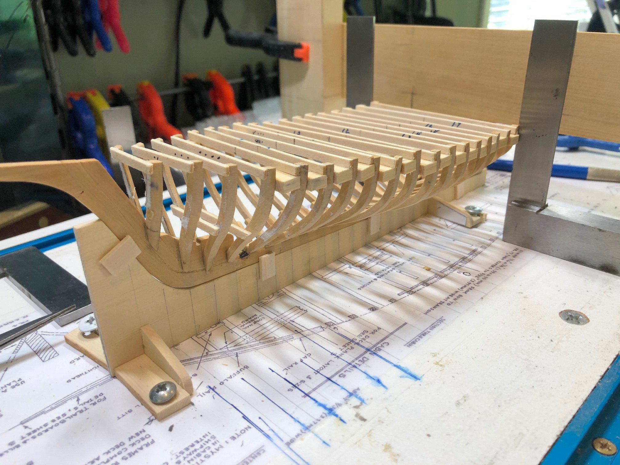
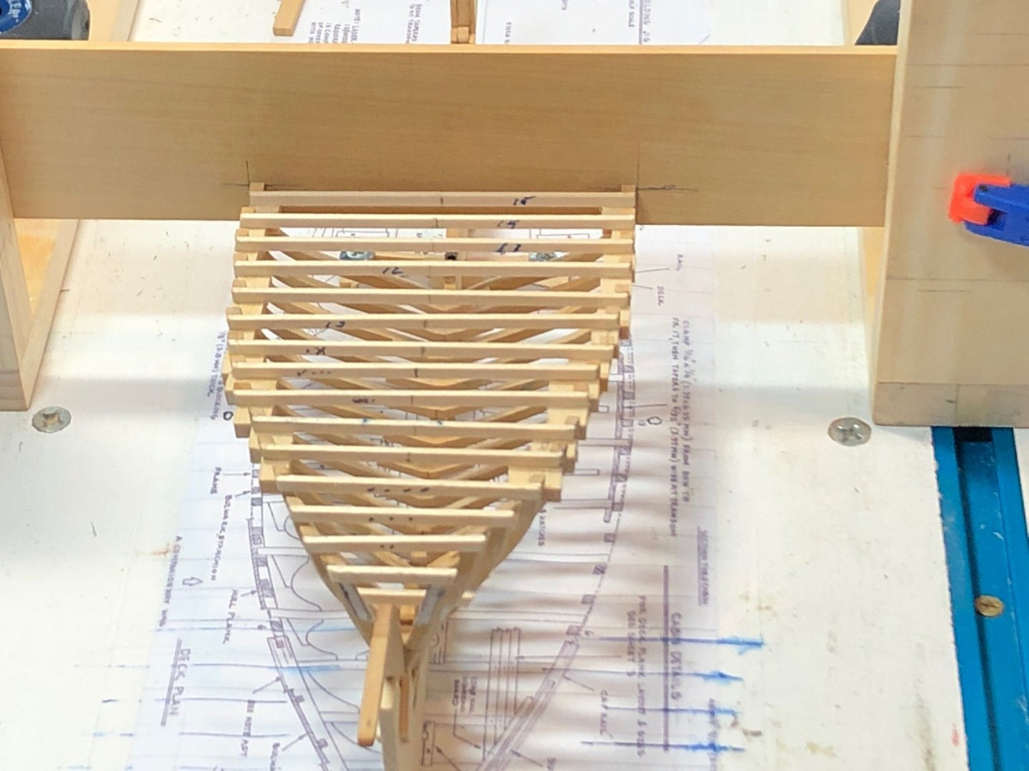
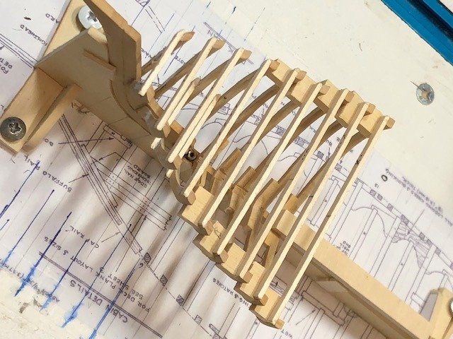
Frames continued: Frames 1 - 18 are installed. #s 17 & 18 are the first of the after-most frames that lodge on the deadwood rather than on top of the keel. There are notches on both the deadwood and the frame set that need to mesh and align with the rabbet. Having floors on the frames and the 1" wider keel / stem & stern complicates the installation. I'm also going to have to put temporary spacers between the first four frames, otherwise fairing the sheer and sides of the frames will be impossible. Maury

-
Glue; temporary vs permanent: Throughout this build I have assumed (maybe wrongly) that inexpensive "school glue" is easier to dissolve than PVA. For all of the "temporary" gluing of braces between frames, as well as the oval molding described above, etc. I've used the white school glue. I use the same (diluted 50% with water) for gluing the frame patterns to the boards. First Mate asked if I'd tested that...and the answer is not yet...but I should do so. I had to re-do one of the frames and the "school glue" did seem to come undone quicker. Maury
-
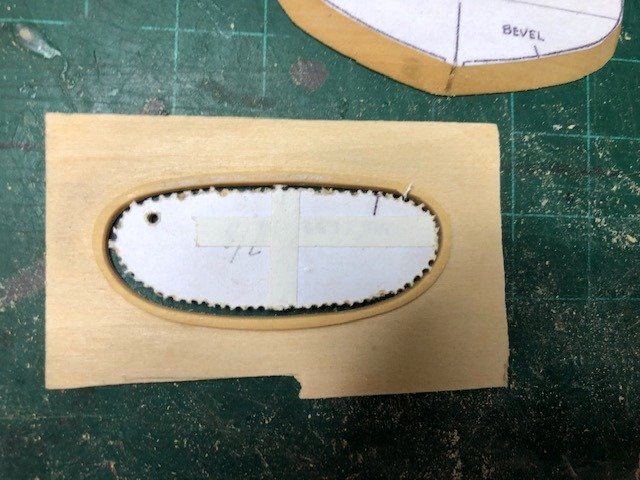
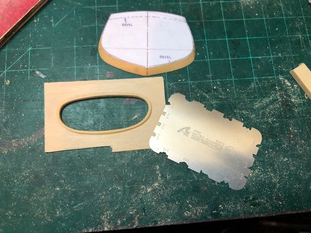
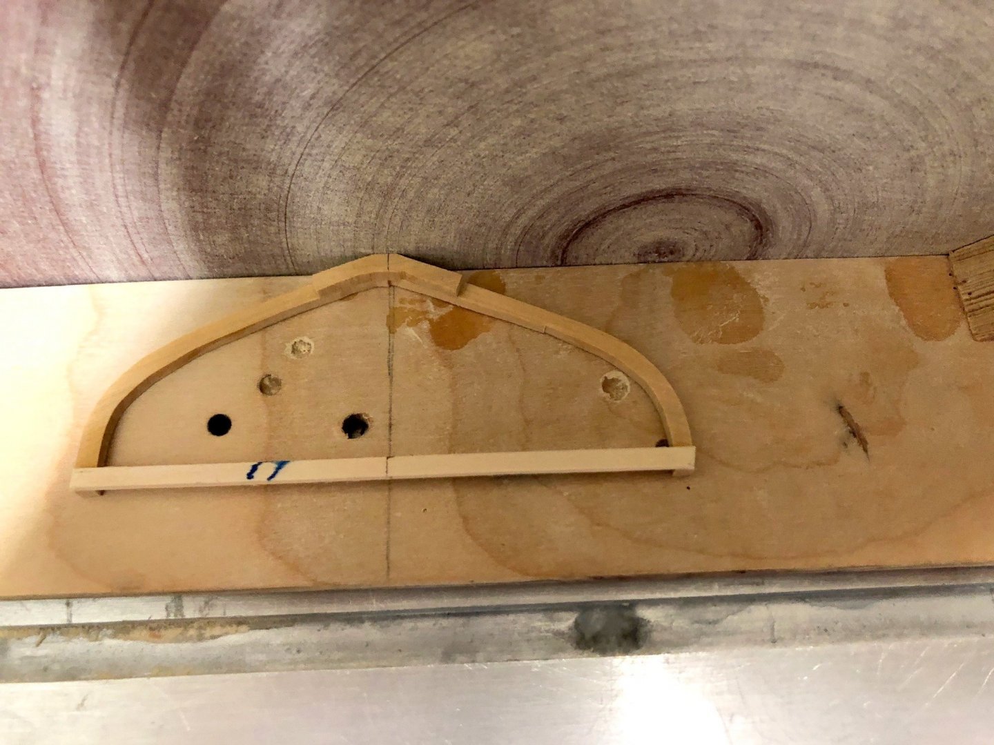
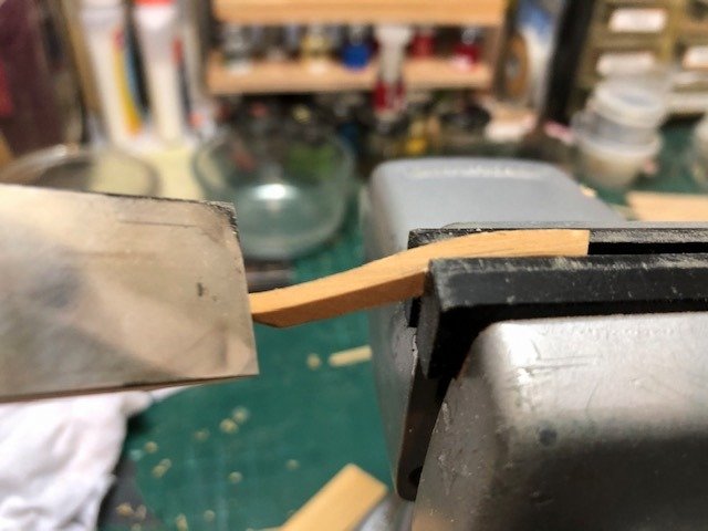
While waiting for glue to dry... The transom has a half-round oval(ish) molding that surrounds the name and home port. I cut out the pattern, cut and sanded the outside to the line. This photo is after the center piece was cut out. Since it's less than 1/16" thin, I then glued it to a sacrificial carrier piece and drilled out the center (a bunch of holes near the inner line. A bunch of sanding and scraping later it looks as it should. Rather than glue it in place on the transom, I'm going to paint it (gold) while it's still on the carrier and remove it and glue it on the transom later. Maury
-
Sherline Maury
-
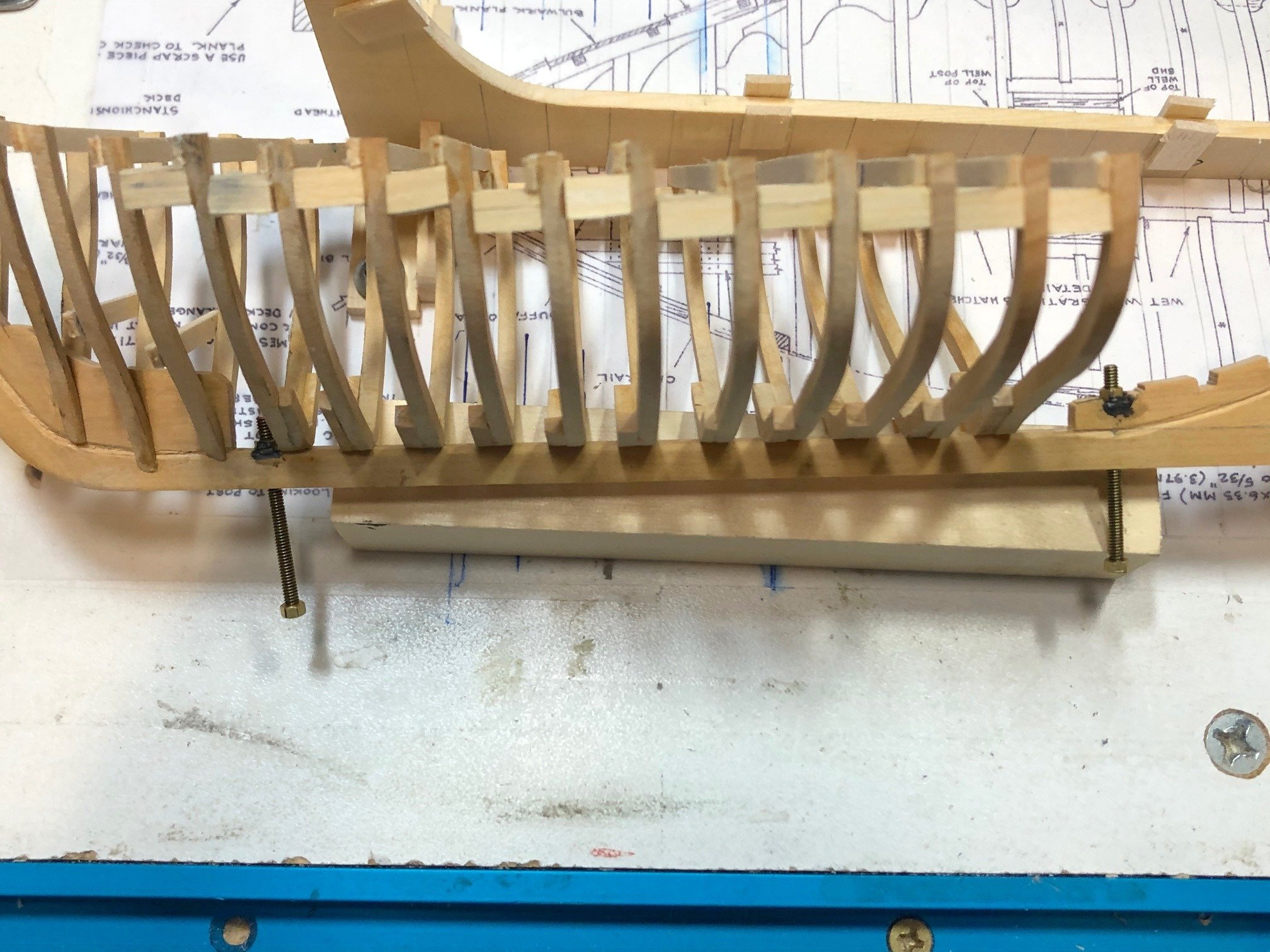
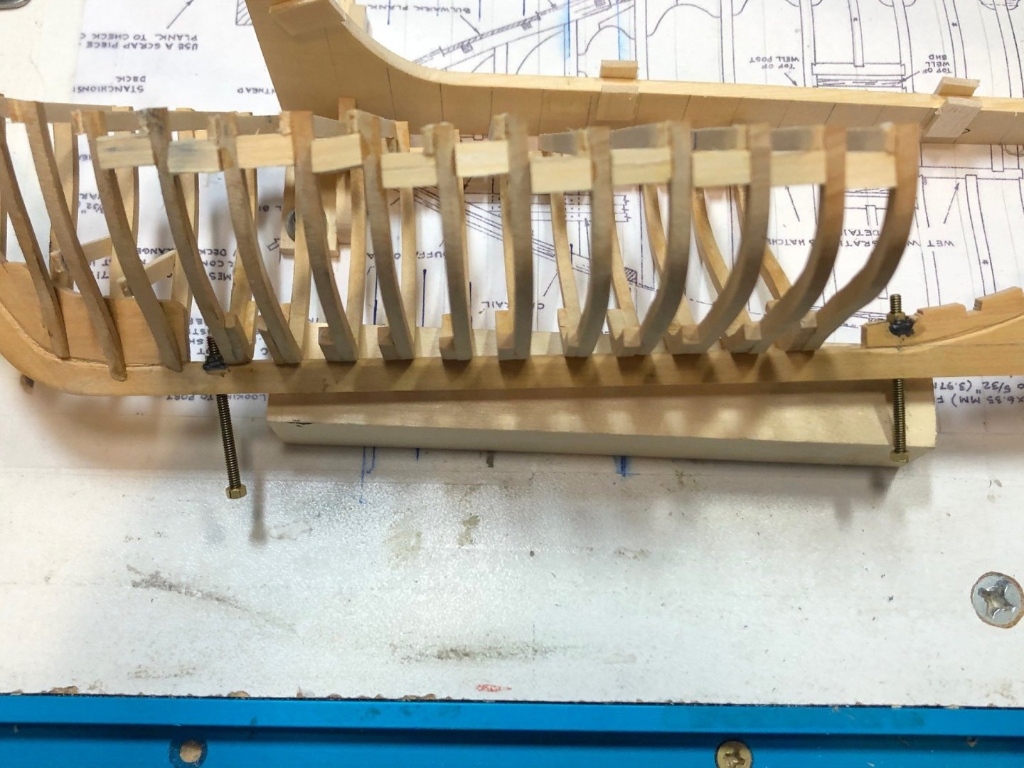
I followed Druxey's advise re. the retaining bolts / nuts. Worked this time. I lightly oiled the bolts, inserted them in the holes, held in the slots and very lightly applied some epoxy. The bolts turn freely. There is a big lens distortion in the photo. The bolts are parallel to each other and at the angle created by the building framework. Maury
-
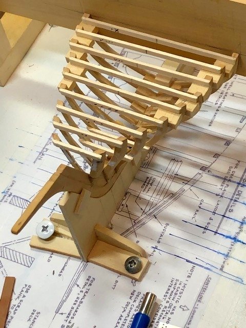
Frames Installation: Proceeding frames 1 - 15. Dead Flat is at 13 (although they number frames 1 - 26). Frame 6 was re-centered and leveled. Frame 15 is being held against the gantry cross-bar until the glue sets. I have not yet replaced the hold-down nuts. Any suggestions on how to (epoxy) them in place without fouling the nuts would be appreciated. Maury
-
Cutting, assembling and installing the frames continues. A couple of notes... I'm installing floors on most all of the frames, even though the plans call for every other frame. The surface of the frame bottoms where the two sides meet is not enough for an adequate joint. Making sure the bottom of the frame set is parallel to the line between the tops of both sides, I mark the center at both the bottom and on the temporary cross member. I use a sled on my circular sander to get a "zero clearance". Small pieces have been forced between the table and the sanding disc without it. I also have a 90 degree line marked on the sled. When sanding the bottoms of the frame sets, I make sure the marks on the frame line up with the line on the sled...always a proper and flat sanded. Maury
-
Swan-Class Sloop by Stuglo - FINISHED - 1:48
Maury S replied to stuglo's topic in - Build logs for subjects built 1751 - 1800
Thanks, that puts things into perspective. Maury -
Swan-Class Sloop by Stuglo - FINISHED - 1:48
Maury S replied to stuglo's topic in - Build logs for subjects built 1751 - 1800
Druxey, Hard to tell the size from the photo. How long and wide is your example? Maury -
Ron, Thanks for the tip. I ran the bolts in and they did not catch. Have to re-do those. Better now than later. Maury
-
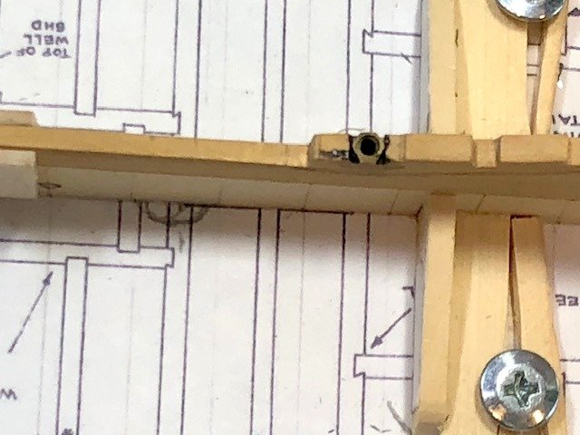
Before installing the next frames, the retainer nuts were installed. A slot was cut in the deadwood at the hole for the the retaining bolts. A small dab of epoxy and the nuts were put in place, making sure the epoxy did not clog the nuts. I went with 2-56 nuts and bolts so I wouldn't blow out the keel with the hole. Then frames 5 - 9 were cut, beveled and made up. I put a floor on all 4 frames to help stabilize them. Spacers were inserted between each frame and the previous one (held with regular "school glue"...easier to undo later). The starboard side of Fr 6 seems out of alignment. I'll come back to that. Once all the frames are in, temporary stringers will hold all of them in place so the spacers can be removed. Maury
-
Yes, I have that book. Very helpful, and remember, those photos were taken in the 1930s. Some changes from 1877 and 1866. Maury
-
Will, The lines on the cross bar are erased and re-done for each frame. That way the sheer is correct as is the centering of each frame. Maury
-
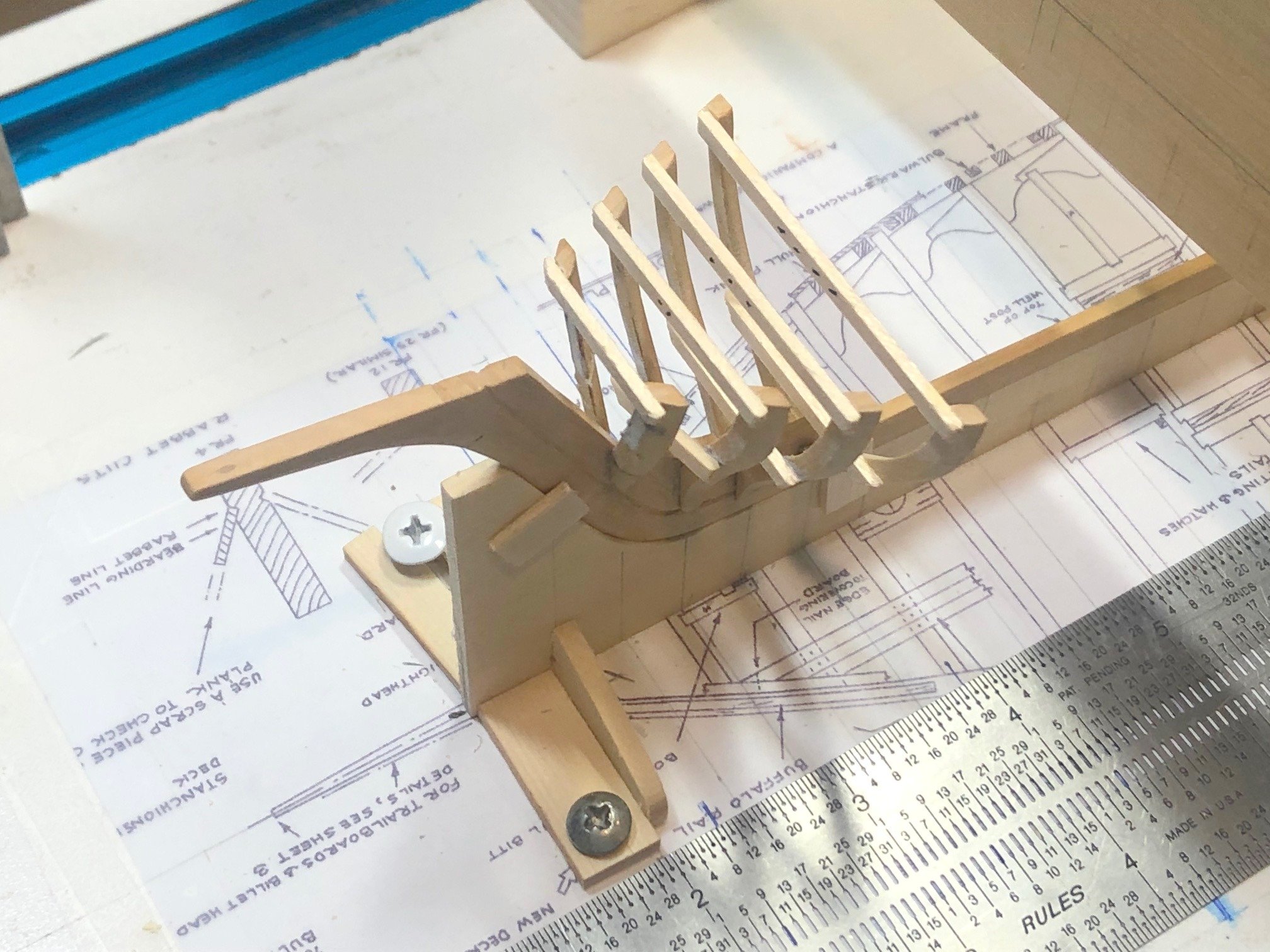
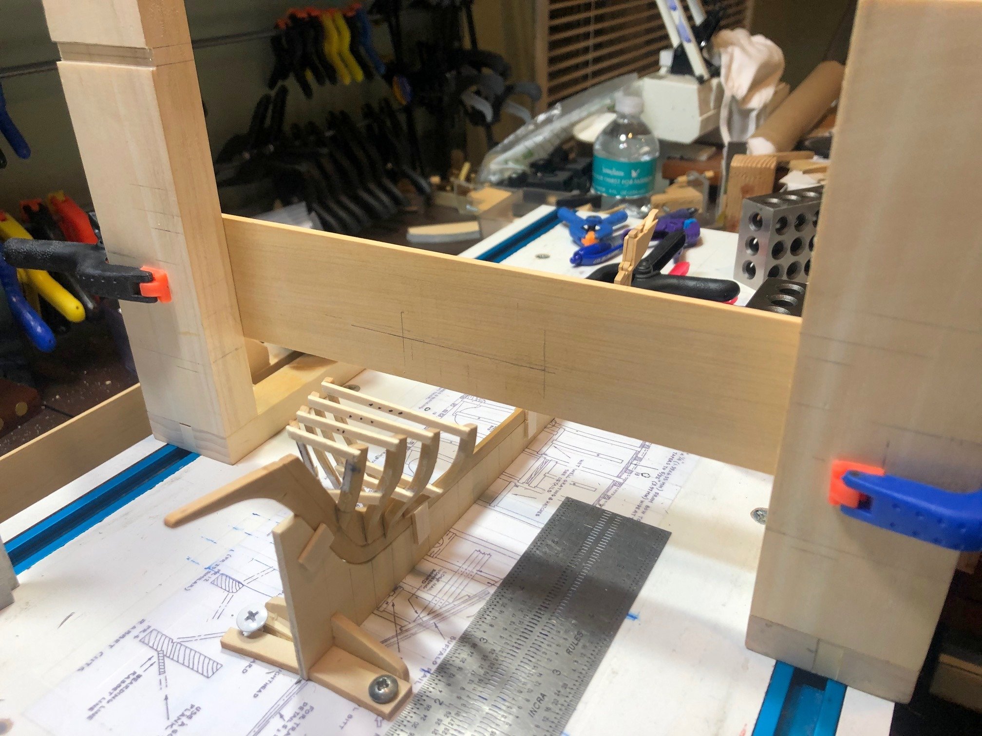
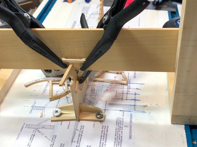
First Frames Installed: The first four frames are installed on the keel structure. More on the gantry. The height of the top of the frame, taken from the sheer plan, is marked (horizontal line on cross bar). The front face of the cross bar is aligned with the aft side of the frame using a square, from the line on the half breadth. The outer edge of the top of the frame is marked by using a square from the half breadth plan on the building board (vertical line on the cross bar). Clamping the frame in place on the cross bar assures it is plumb and perpendicular to the building board. Clamping the bottom of the frame holds it against the deadwood while the glue sets. The next frames just sit atop the keel, so additional techniques will be required. Maury


-
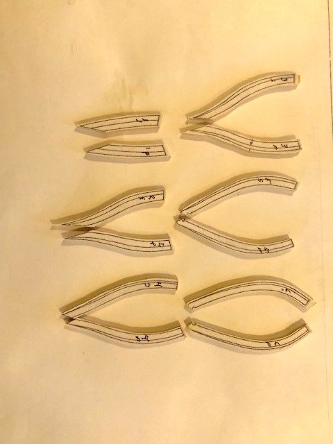
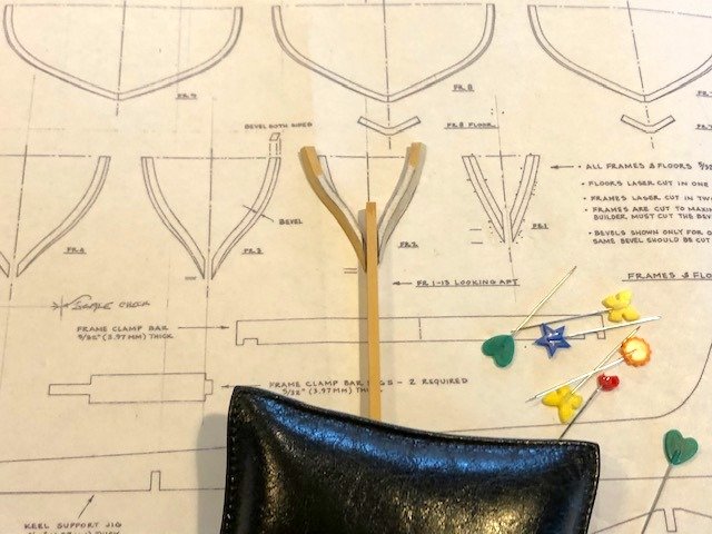
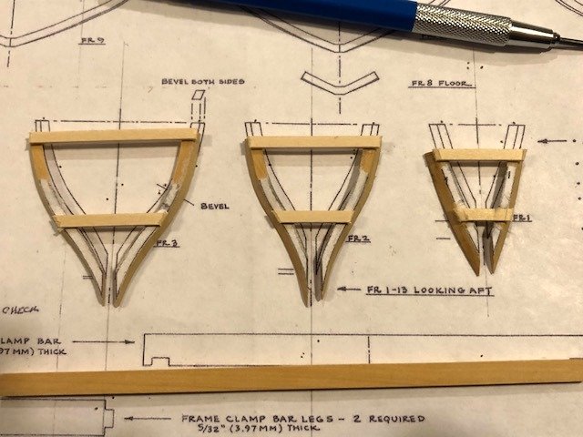
Cutting Frames: The frame shapes (frames 1 - 6) are cut and pasted on 5" [0.1042"] thick box wood (I think AYC is not strong enough nor easy to cut bevels for frames). They are cut on the scroll saw and sanded on the disc sander (convex surfaces) and the oscillating spindle sander (concave surfaces). The frame parts need beveling on both the inner and outer sides. I find using a full-sized (sharp) chisel is easier to control than an X-acto type knife (hat tip: David Antscherl). The beveled frame parts are laid over a clean plan, pinned in place and temporary braces are glued on. A Keel-sized timber is used to set the space of the deadwood. First three frames ready to be installed on the keel assembly: Maury
-
Netflix has a new series about pirates in the early 18th C. Dramatical and some historical. Fun if you're into pirates. Maury
-
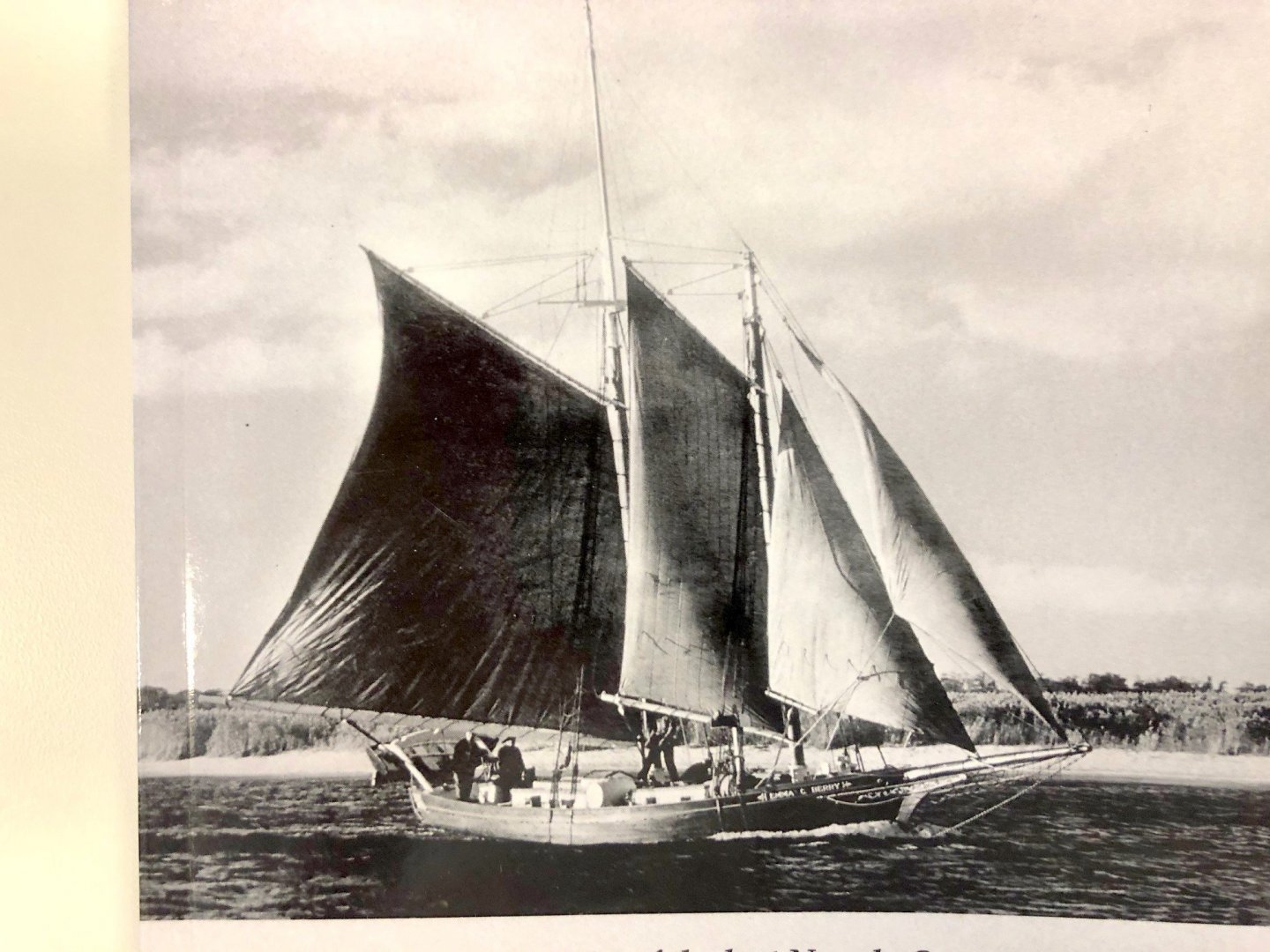
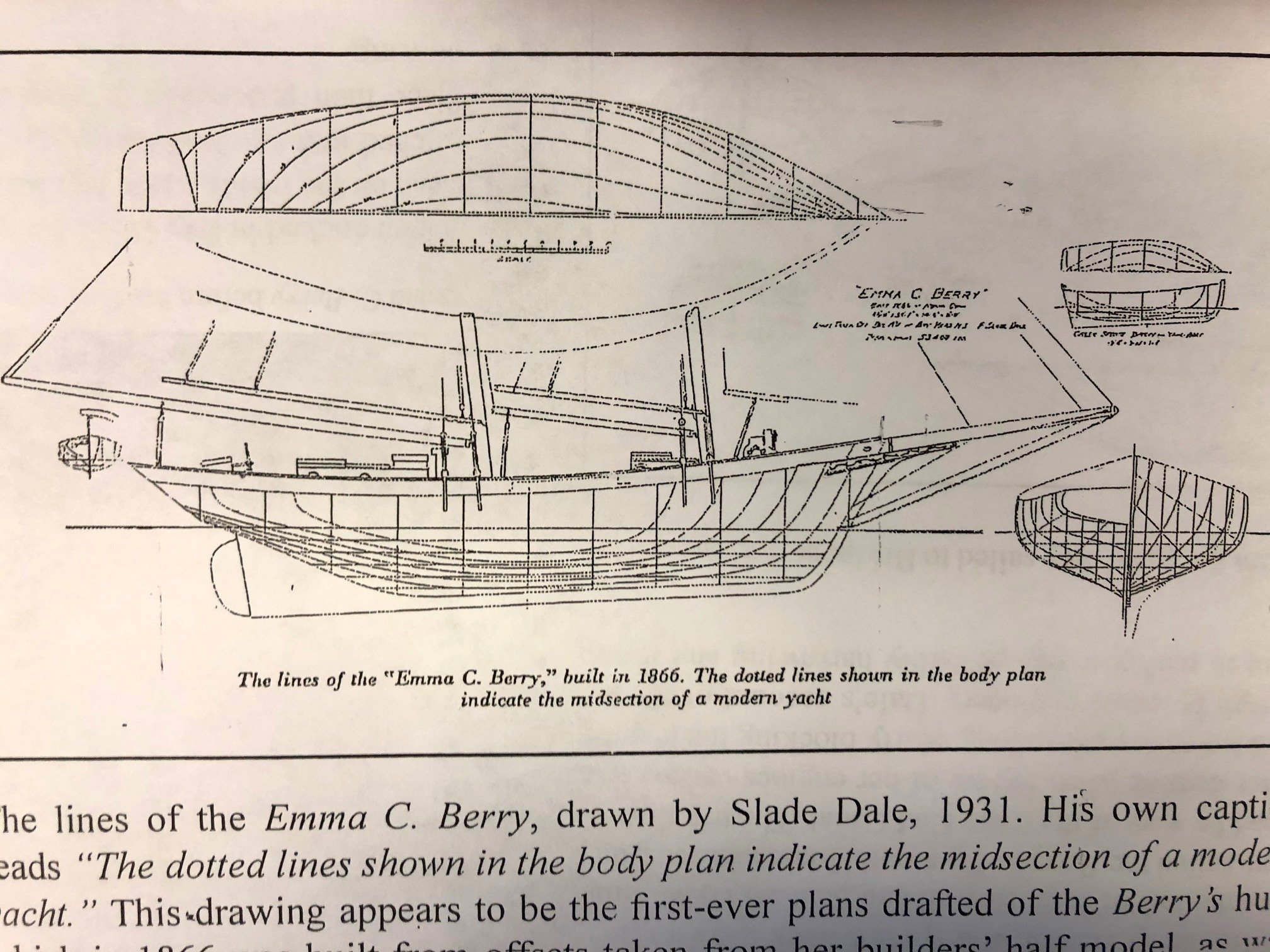
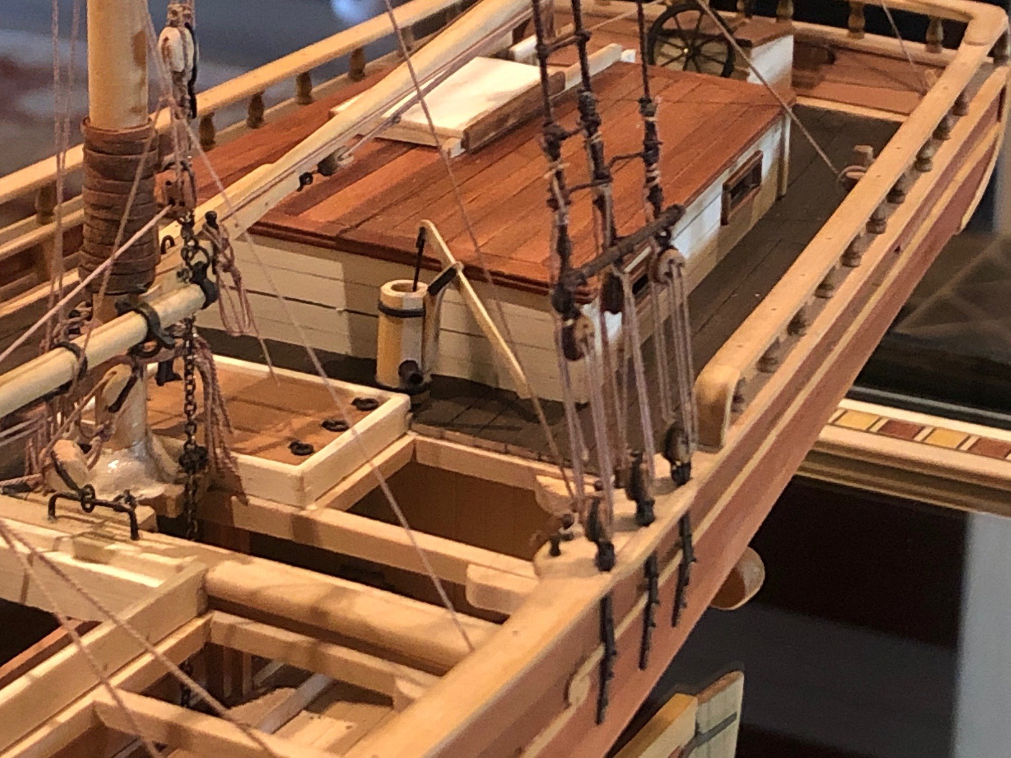
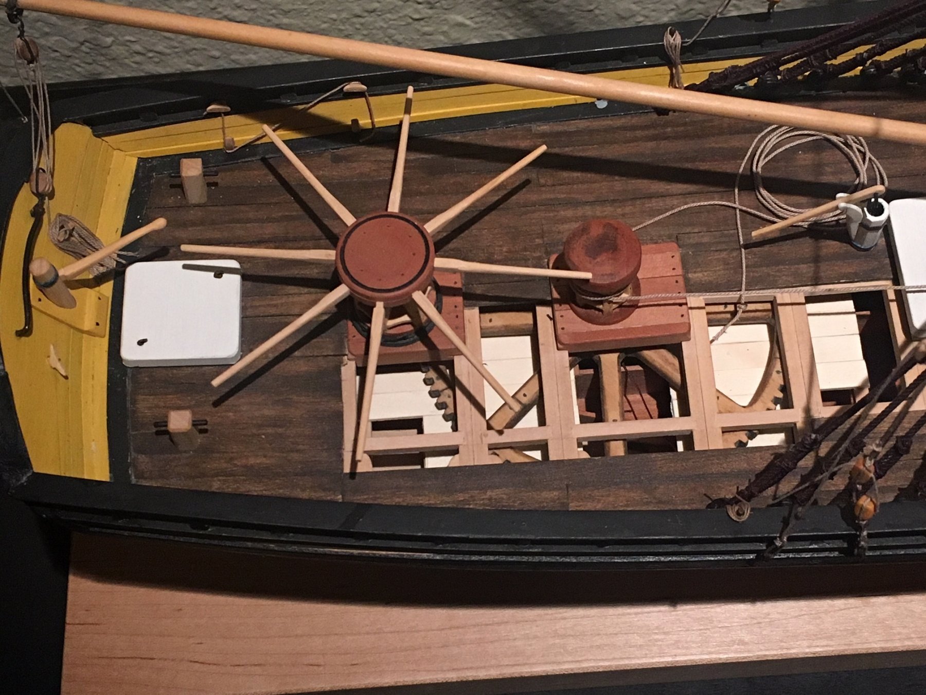
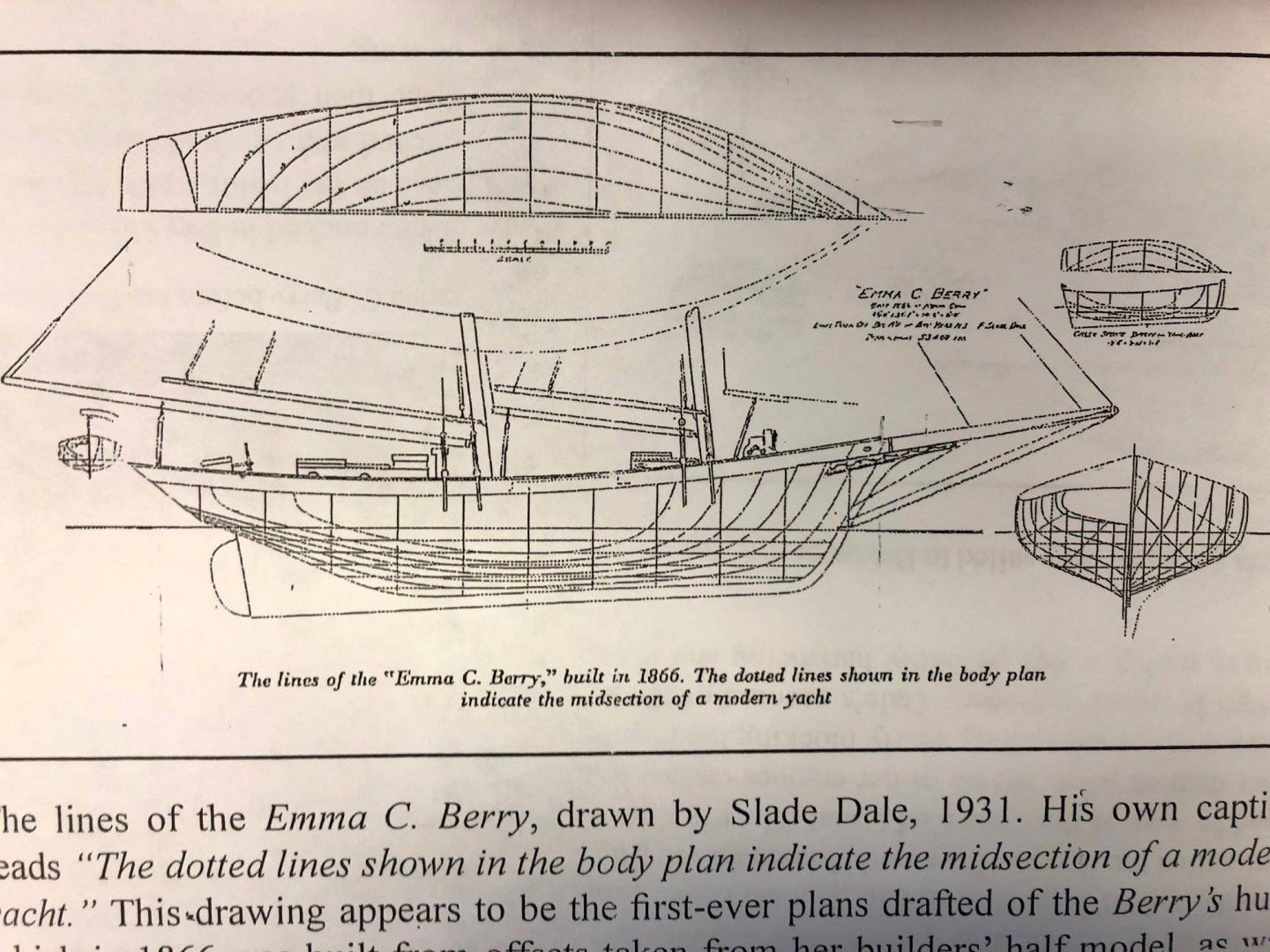
Resolution of schooner plan with photos: "Celebrating the EMMA C. BERRY" by Lawrence Jacobsen shows the "first ever plans drafted of the Berry's hull dated 1931". (In 1866, she was built from lines taken off a builders half model). The location of the fore mast is identical with the plans of Berry as a sloop. The location of the main mast shown on the 1931 plans puts the mast-step inside the wet well which was not altered in 1887. I compared those plans with the photos of her and found the photos show the main mast about a foot aft of what is shown on the sheer plan (and therefore aft of the wet well). This info. is critical now, since the mast step needs to be positioned properly on the keelson. To be fair, by 1931, she was no longer used as a fishing boat so the wet well had been removed and the mast could have been shifted forward. That would not have been the case in 1887. Maury
-
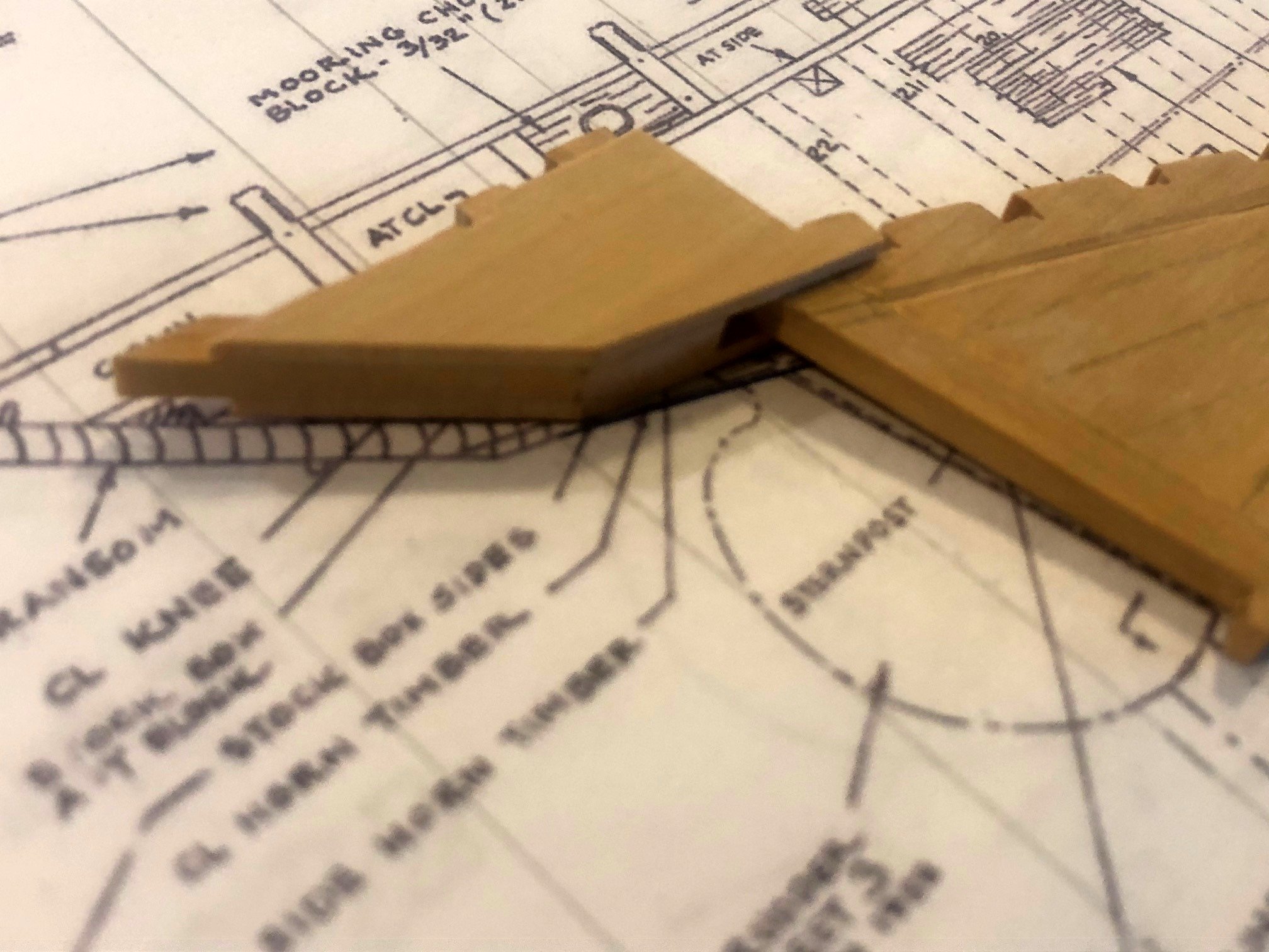
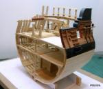
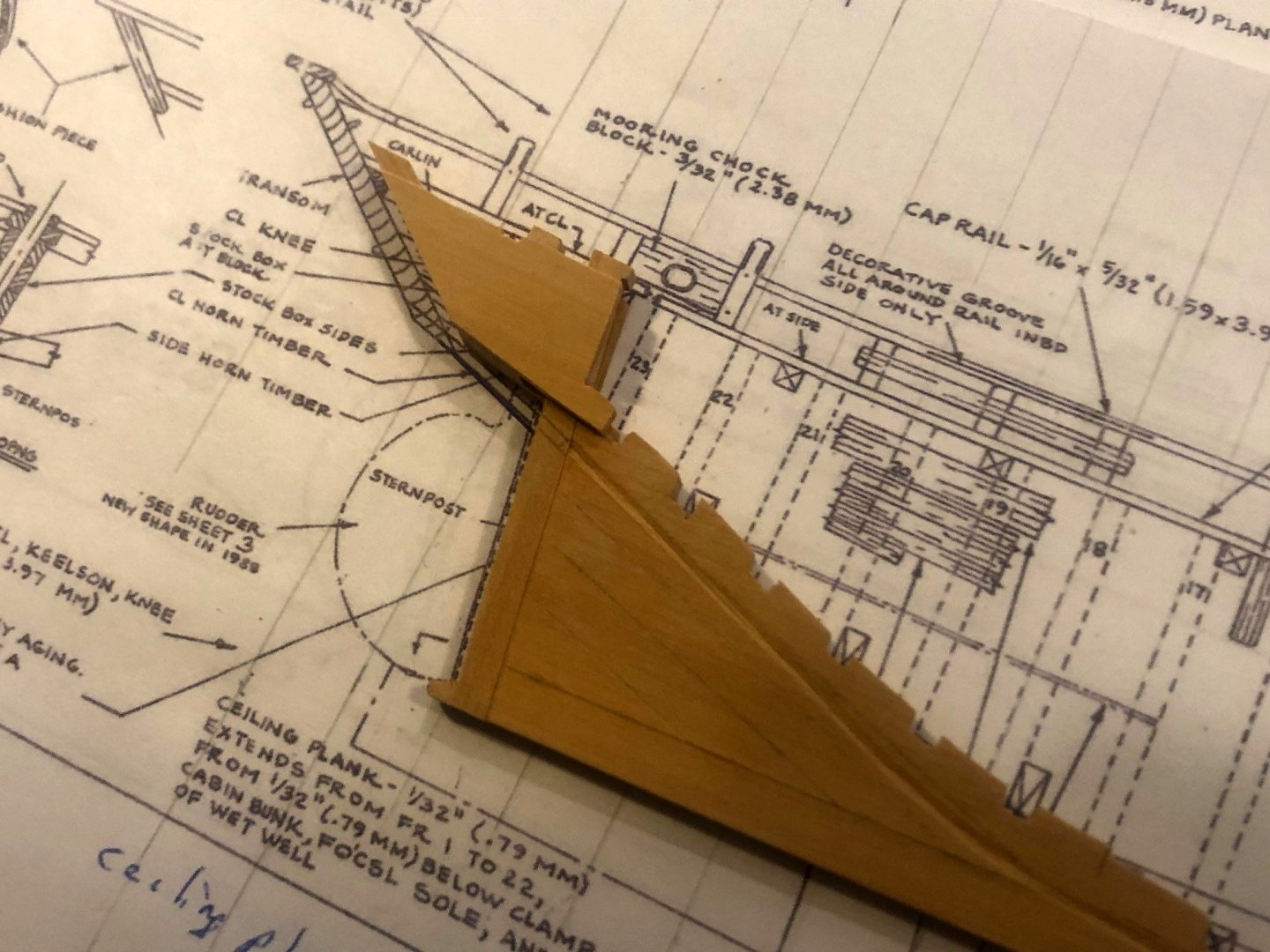
The keel, stem and stern posts and deadwood has been completed. The aft edge of the sternpost was made concave to accommodate the shape of the rudder post. The rabbet was cut and horn timbers glued in place by lining them up on the sheer plan. There are side horn timbers that create a "water-tight" box for the rudder post. It seems the shape of the outer side timbers are not the same shape (on the lower part) as the horn timber. I may have to insert a wedge to line them up. I see no reason that they should not match.

-
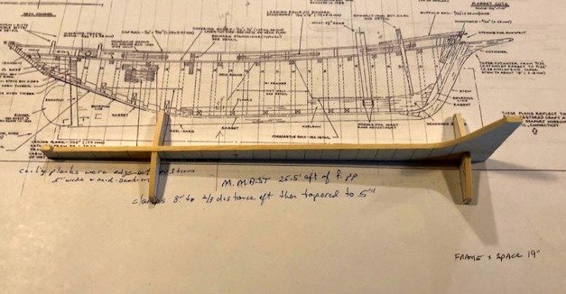
Building board: I'll be using the same building board that I've used for three previous models over the years. It's based on Ed Tosti's plan divulged in his Naiad books. In addition, since ECB is a keel dragger (the sheer is not parallel to the keel, and the frames are not perpendicular to the keel, I'm using a modified rack as included on the plans to hold the keel. The half-breadth plan is taped to the board and the rack is glued and screwed over the plan. (Plan shown above is the Sheer Plan, not the HB). The frame locations are extended out from the edge of the drawing so the gantry can be aligned as each frame is installed. Maury
-
Thanks for all the encouraging comments. As many of you know, I have chosen to stick to merchant ships. (This is NOT ideological). I just can't see spending months making 74 cannon carriages. I went to 1:48 because I have been accustomed to converting everything to that scale. Display space and workshop size limitations are also a factor. The 1:32 model takes up a bit of space. As to comparisons to the 1:32 sloop POF kit, the hull is exactly the same layout (and the lines are beautiful). Locating the main mast through evaluation of the many photos I've gathered is pretty straight forward. The wet well remained until the 1920's when it was used for more general cargo handling and eventually people. Very minor changes on deck. It is going to be another learning experience...more metal work detail and cleaner wood work (I hope). My supply of BOX wood is limited so the bones will be box and planking probably Alaskan Yellow cedar. The AYC I've used is not nearly as strong and splits quite easily. This one will be painted. The Noank fleet was traditionally green below the bulwarks. There is a possibility of furled sails appearing on this model. We'll see. Maury
-
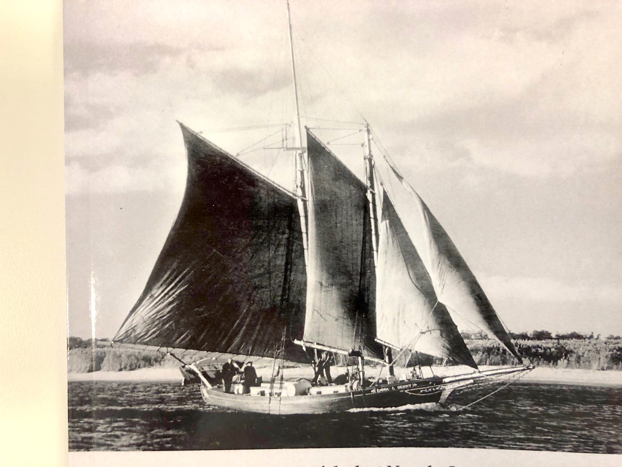
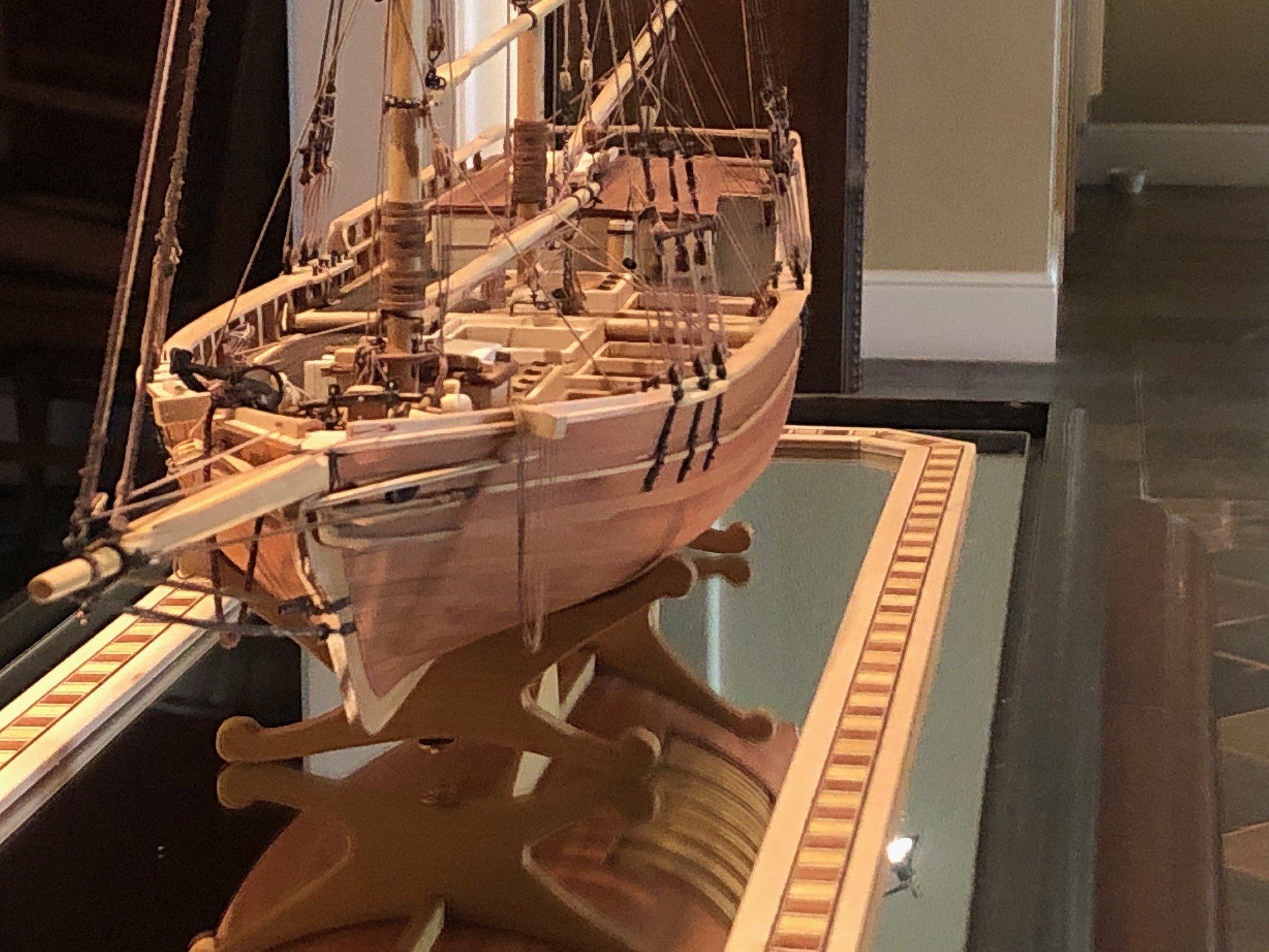
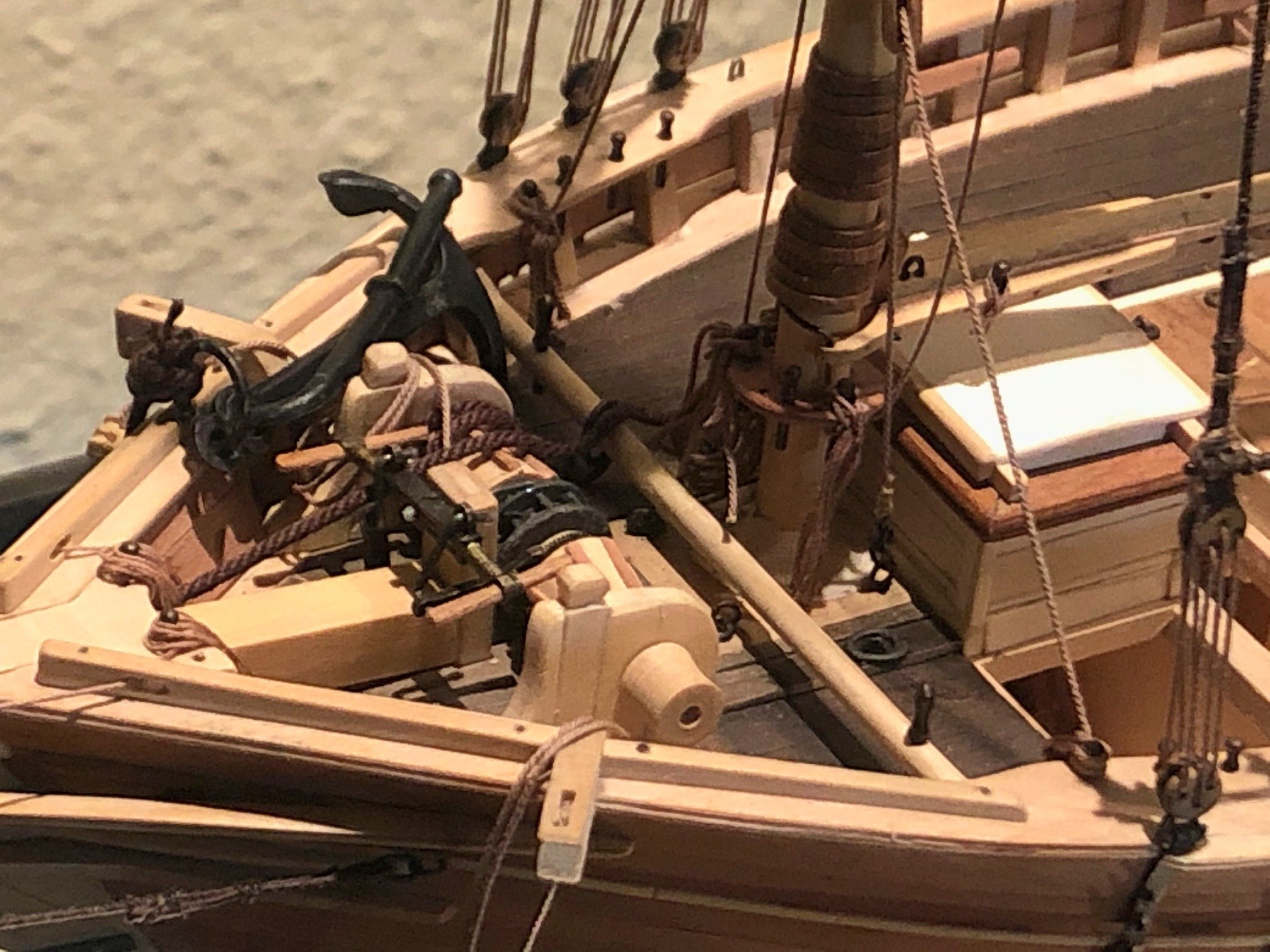
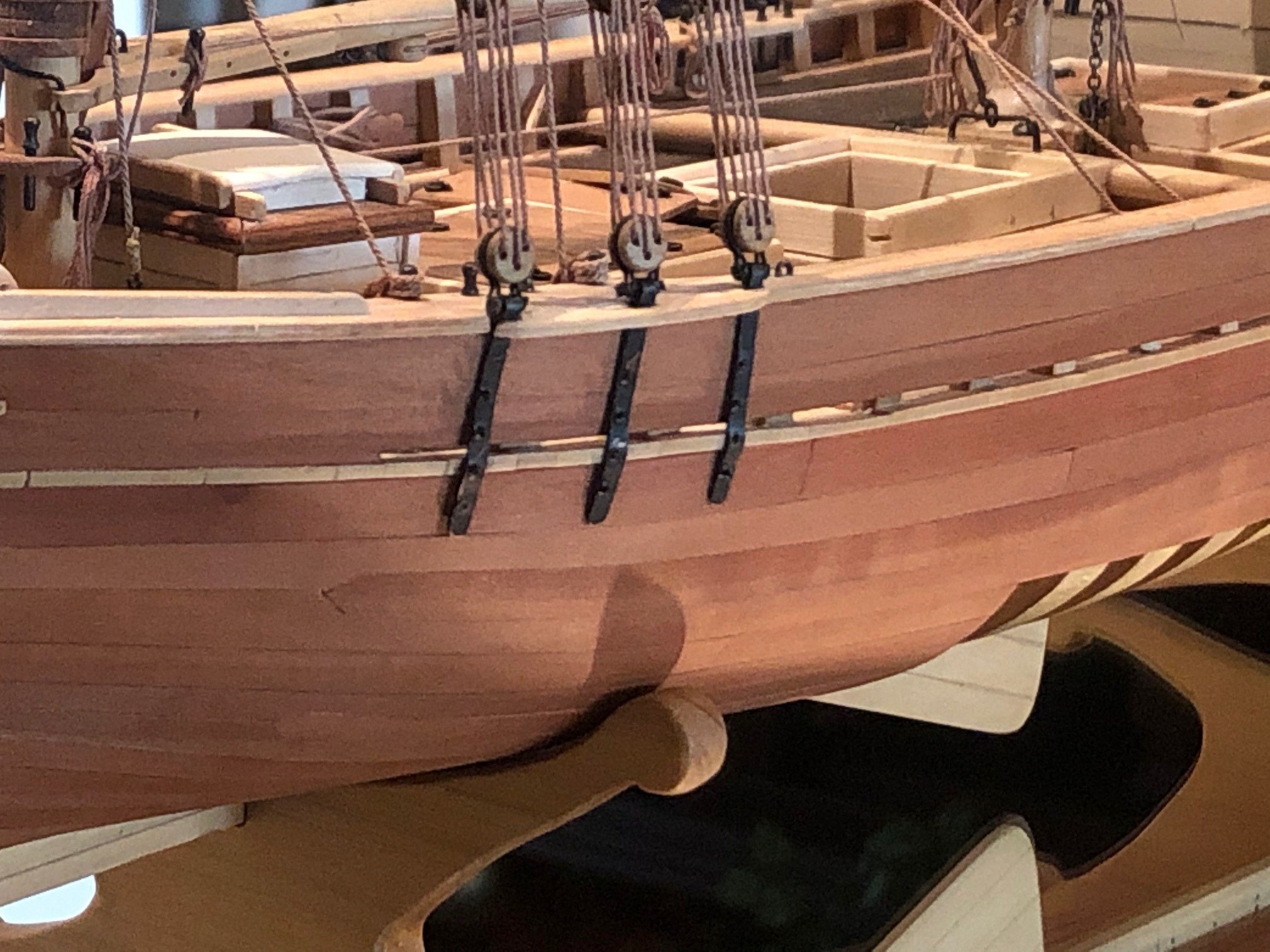
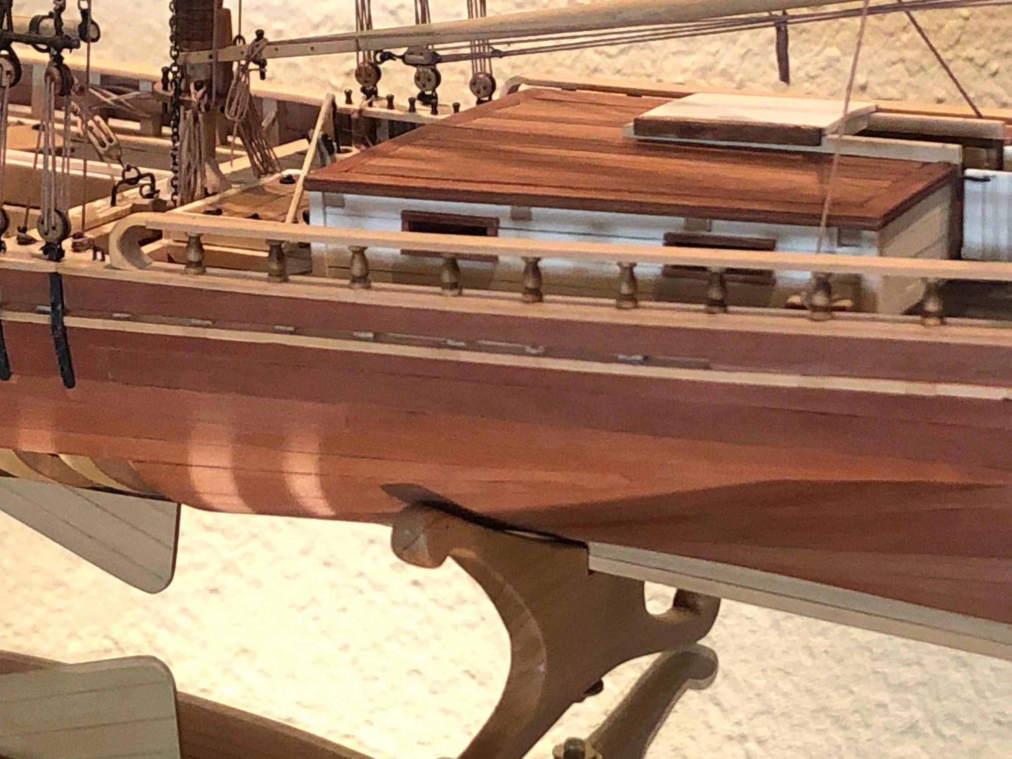
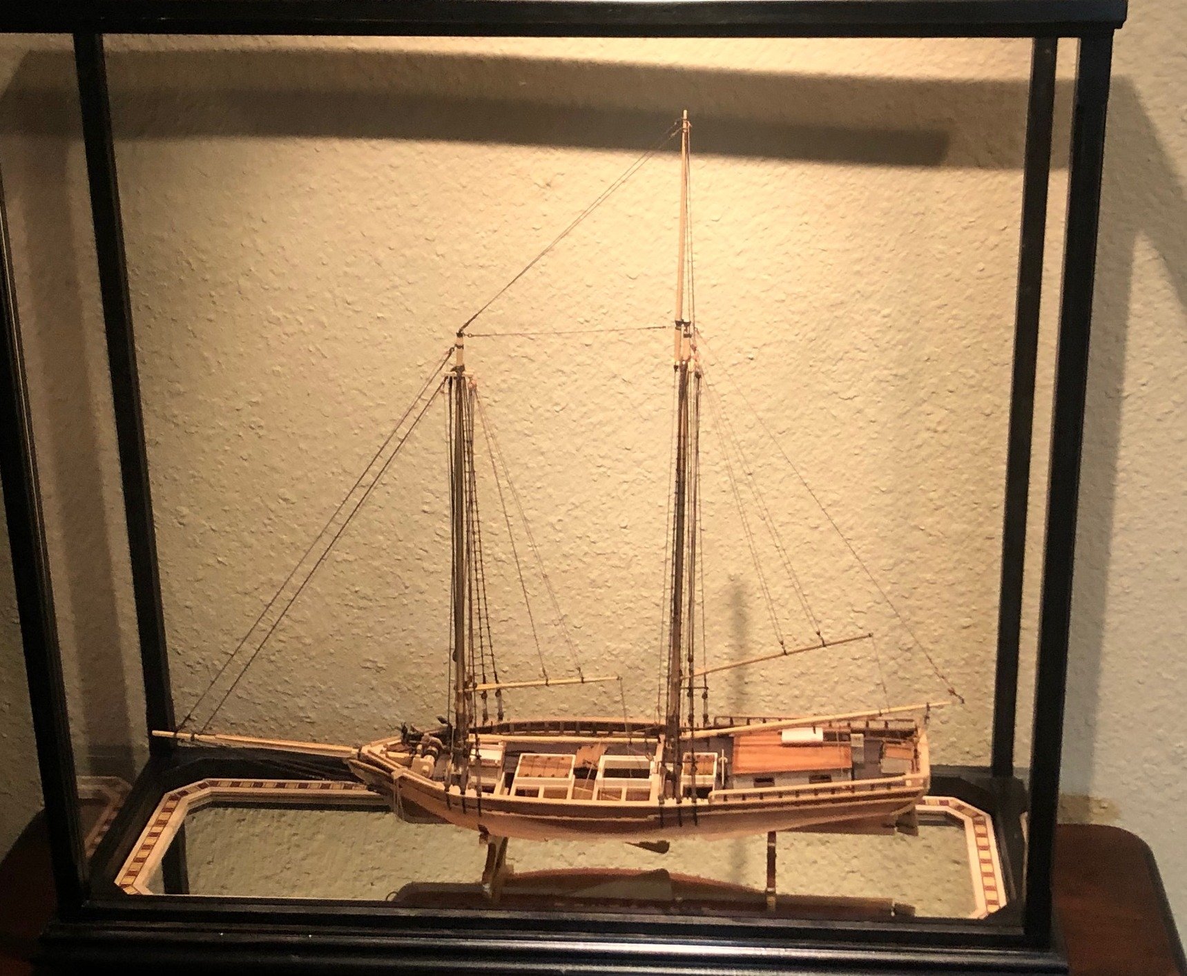
Emma C. Berry as a schooner The Berry was originally built at the Latham Yard in Noank, CT (near today's Mystic Seaport) in 1866 as a gaff sloop. John H. Berry, a Noank fisherman, commissioned a well smack sloop (a small fishing vessel with an internal wet well for storing the catch) for $1,275. She was launched June 8 and has been “restored” several times over the last 155 years. The Emma C. Berry was declared a National Historic Landmark in 1994 and is one of the oldest surviving commercial vessels in America. In 2015, Lawrence R. Jabobsen published “Celebratthing the EMMA C. BERRY” for the Noank Historical Society. It is a pivotal history of the last remaining Noank smack. After serving for 20 years as a sloop, she was re-rigged as a schooner in late 1886 /87 at either the E.P. Beckwith Shipyard or the nearby Crocker/Davidson Yard in New London CT. The main reason being the ease of handling several smaller sails, allowing a smaller crew to handle the vessel. Model Shipways (division of Model Expo) offers a very good plank-on-frame kit as the restored sloop in 1:32 scale. Sterling Models sells a solid hull kit as a schooner, and I cannot comment on the quality. In all the years I've been on MSW, I've not been aware of anyone doing a true POF model of her as a schooner. To this day, I think the Berry is one of the most attractive boats I've seen. Perhaps that is a reason the actual boat has survived so long. I purchased the excellent plan set (Ben Lankford, 1994) from Model Expo and converted everything to 1:48 scale. I have collected over 100 photos of her as a schooner (mostly dated in the 1920s and 30s.) I think I have every book ever published on the restorations. These provide tremendous detail of the scantlings so off I go on my next project.