HOLIDAY DONATION DRIVE - SUPPORT MSW - DO YOUR PART TO KEEP THIS GREAT FORUM GOING! (Only 20 donations so far - C'mon guys!)
×

Mike 41
-
Posts
439 -
Joined
-
Last visited
Content Type
Profiles
Forums
Gallery
Events
Everything posted by Mike 41
-
 Hi Grant, this is a copy of the jig (Building Board) I am using. Mike Building Board.pdf
- 47 replies
-
- 4
-

-
- Fubbs
- Weasel Works
- (and 1 more)
-
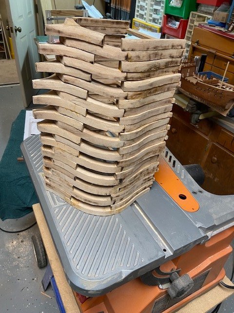
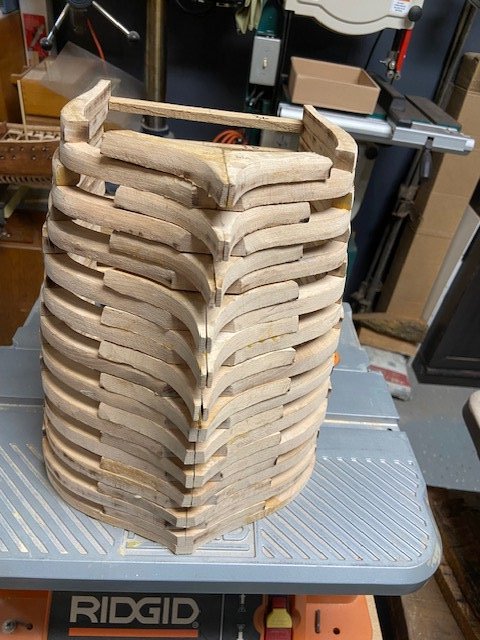
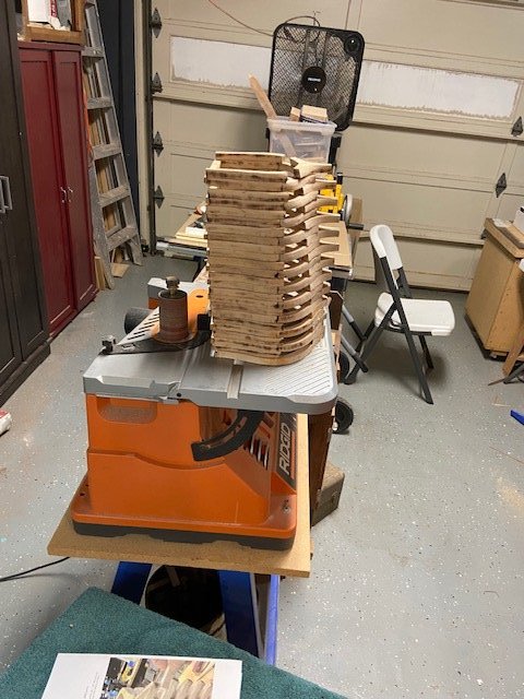
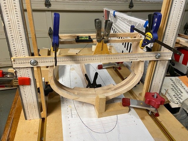
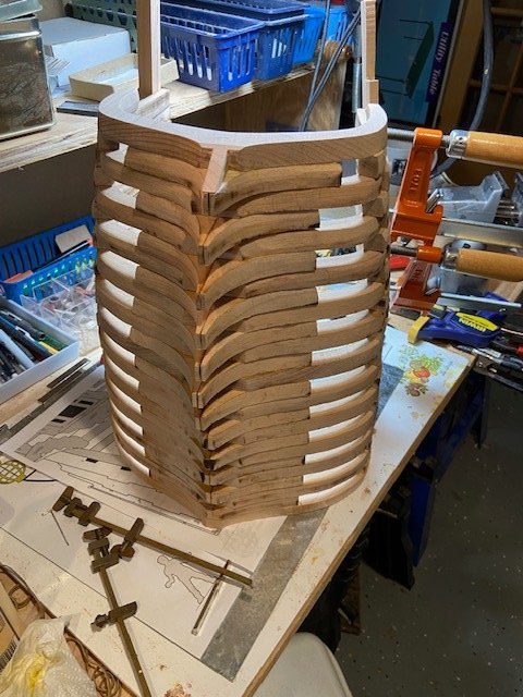
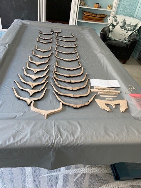
Frames continued: When Mike Shanks assembled the hull, he used a vertical stacking system. He described ever step with detailed photos and easy to understand instructions. The prototype went together quite well, all the frames are square and level. That being said, I am more comfortable with a horizontal build using a jig I have used for many years. I made a vertical stack as a dry run to check the bevels and general alignment. Everything looked good. I left the keel open ended. There is no space between the frames, and it is hot and humid in Myrtle Beach which adds to the expansion / contraction problem. It is easier to trim the keel than rework the frames. I added spacers at the top of the frames, with centerlines to help with the frame alignment with a string line, level and square as each frame is added. A few words about the jig I am using. I designed and built this one in 2012 and have used it for many models. If anyone is interested in the jig, I will post a PDF file here. Thanks for looking in on the build log, any comments are welcome. Mike Progress photos:
- 47 replies
-
- 8
-
-
- Fubbs
- Weasel Works
- (and 1 more)
-
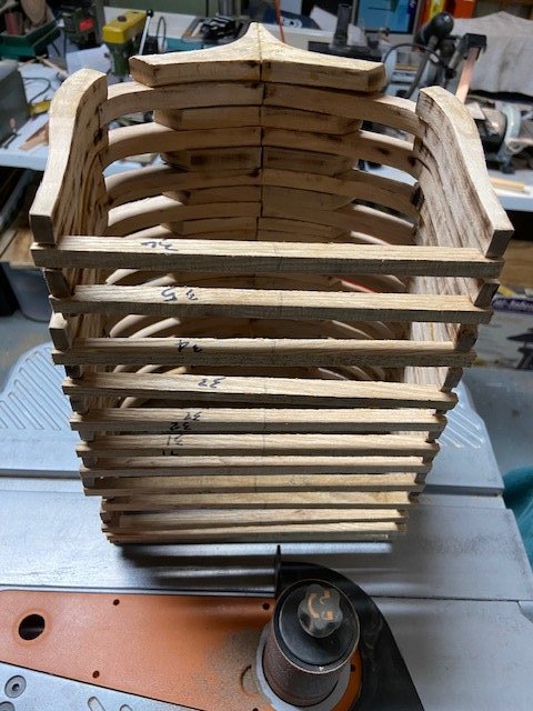
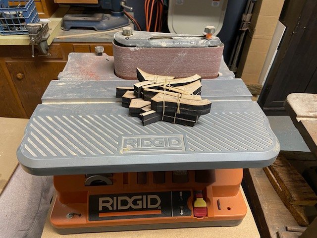
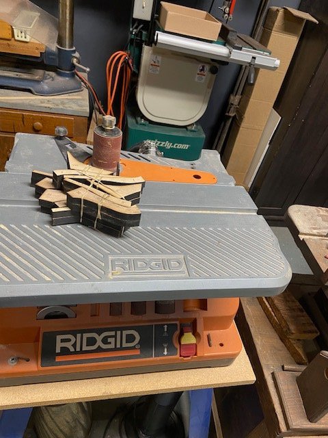
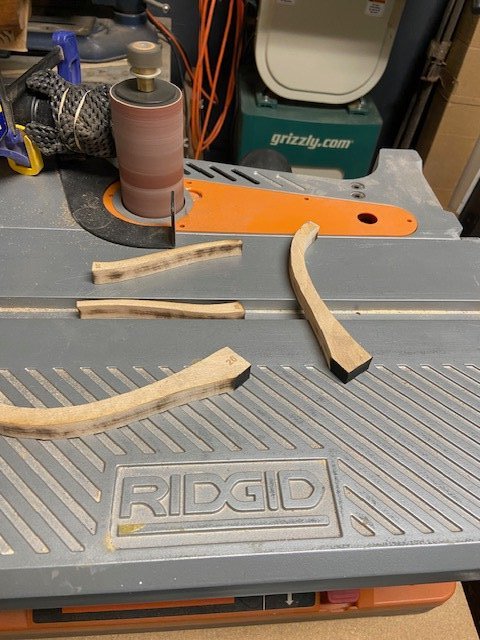
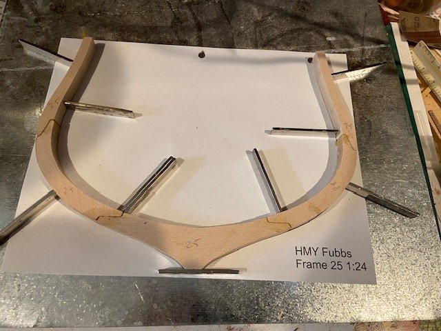
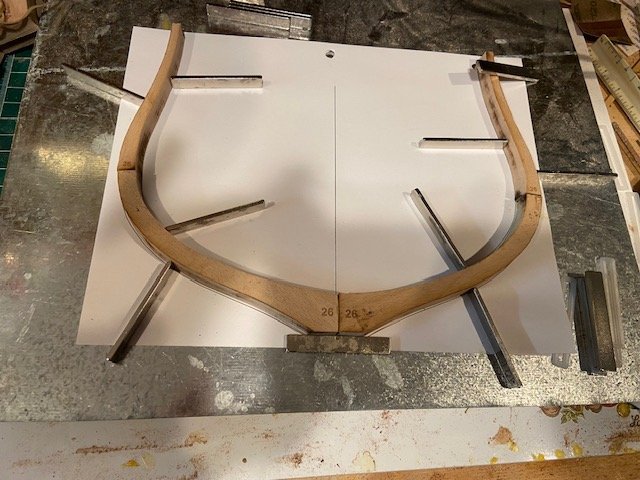
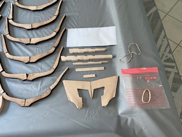
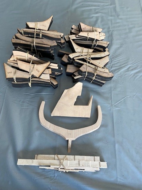
Frames: It has been a while since I built a kit and the first time, I used laser cut frames. The large scale 1:24 made the parts easy to handle the eight pieces are joined with lap joints Making them very easy to assemble, with the exception of frame #25 the forward frame. It was cut using a CNC machine and uses scarph joints that fit perfectly together. After removing the frames from the shipping box, I sorted the frames. Each part has the frame number etched on the aft side of the frame making the orientation easy to maintain. The bevel lines were also etched into the frame parts also. After sorting the parts I bundled them by frame number and divided them into five stacks. Divide & Conquer LOL. Removing the char was not too bad using a spindle sander, but using the port on the machine for the vacuum left a lot of dust in the air so I clamped the hose about a quarter inch off the spindle that removed almost all the dust. I assembled the frames by placing the frame drawing on a sheet metal plate and using magnets to hold the parts in place while the glue dried. When the glue dried, I formed a vertical stack to check the bevels. Progress photos:
- 47 replies
-
- 9
-
-
- Fubbs
- Weasel Works
- (and 1 more)
-
Druxey: Thanks for the information. We are not planning on building another Fubbs model, but I find the ship very interesting.
- 47 replies
-
- 3
-
-
- Fubbs
- Weasel Works
- (and 1 more)
-
Hi Druxey, Our focus is on building a nice-looking model using modern building methods. We are not naval historians, just a few old guys that enjoy building model ships as a hobby. We used Portia Takakjian’s as a resource for the structural components of our model. Has the Stuart Yacht Research Group published their findings on the 1682 version of the ship? I would be interested in seeing the original drawings of the ship.
- 47 replies
-
- 1
-
-
- Fubbs
- Weasel Works
- (and 1 more)
-
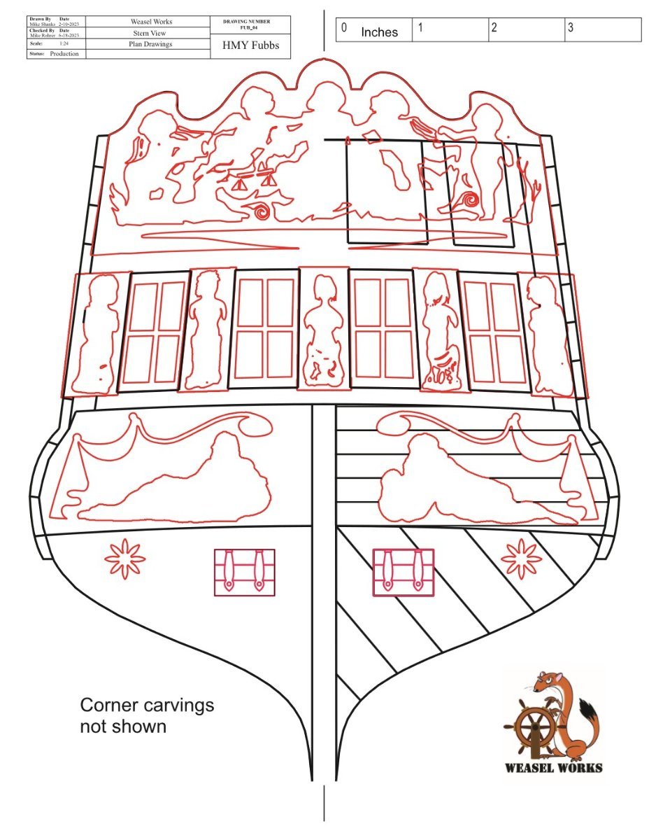
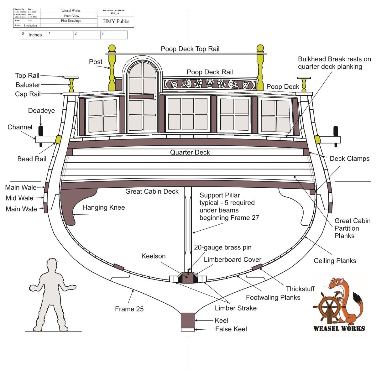
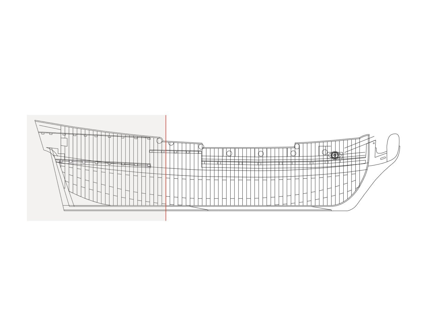
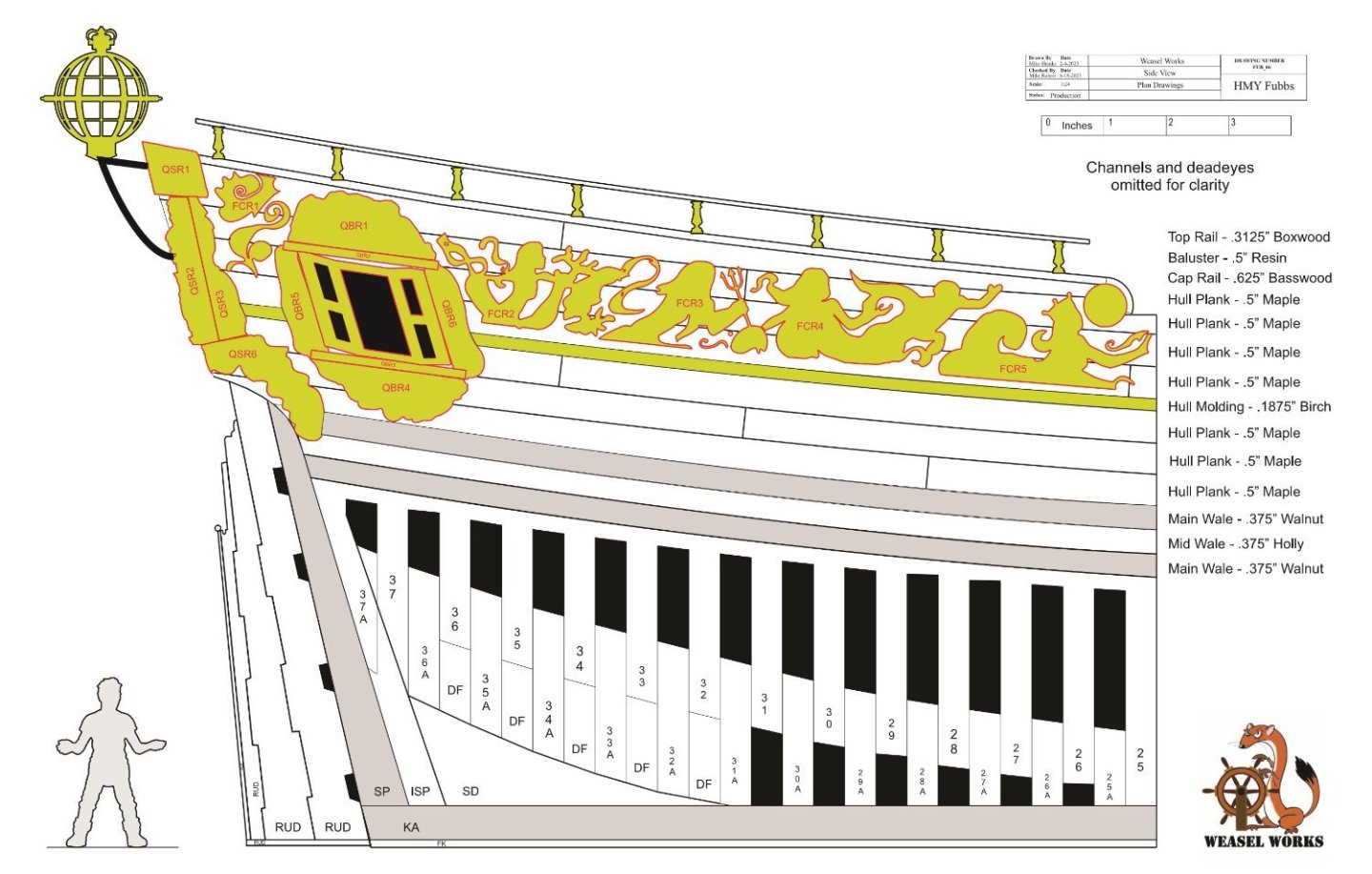
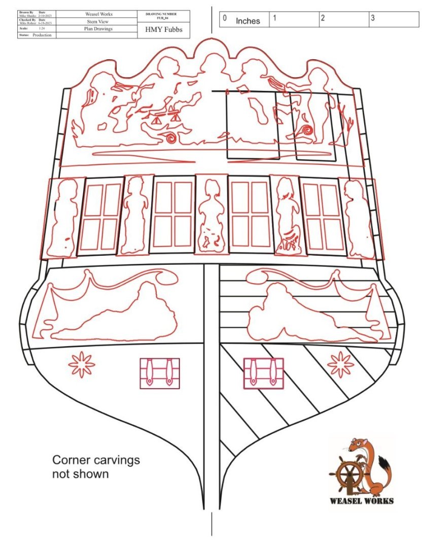
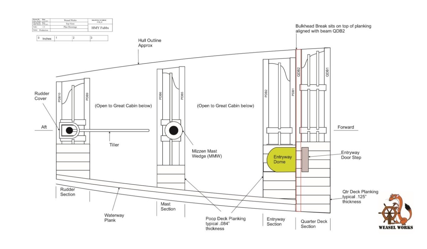
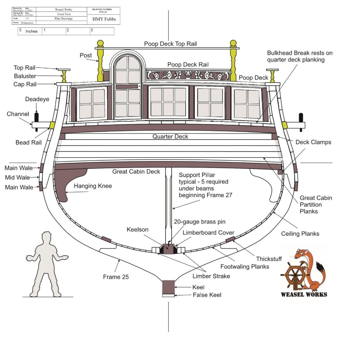
Section Limits: This set of five drawings show the size of the model from different viewpoints. The model is Navy Board Style with stub masts and no rigging. 
- 47 replies
-
- 6
-
-

-
- Fubbs
- Weasel Works
- (and 1 more)
-
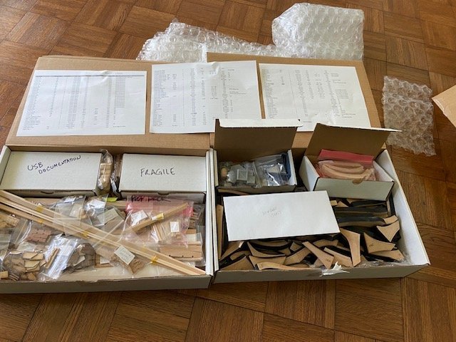
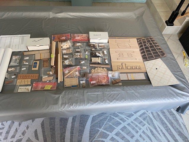
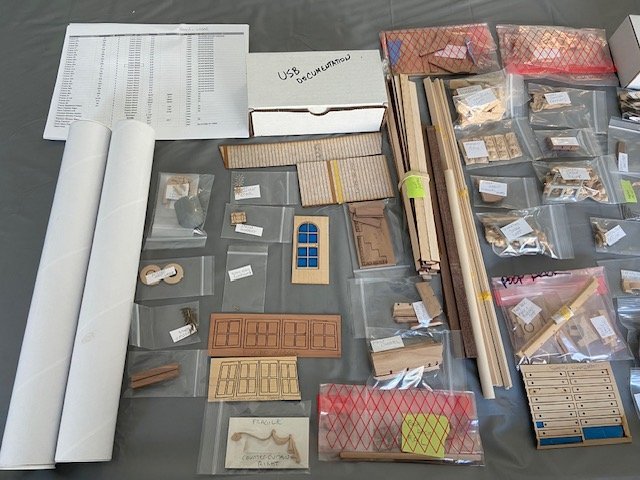
Ship History: His Majesty Yacht (HMY) Fubbs was laid down at Greenwich shipyards by Phineas Pett in 1682. By Royal Navy standards yachts would be the size of a typical harbor dispatch vessel or lightly armed gunboat. HMY Fubbs sported a keel length of only 63’ with at a specified 148 tons fully loaded. With a 21’ breadth and only 9’6” depth in hold these small ships carried a crew of up to 30 and could be armed with 8 – 12 3 pounders. Royal Yacht duties primarily consisted of tending to the affairs of the royal household. Charles II must have enjoyed yacht class vessels as he had 23 of them during his reign – more than any other English king. HMY Fubbs was the most lavish of his fleet of Royal Yachts. Visually, the hull of a Royal Yacht has the look of a 6th rate but is more akin to a ketch-rigged sloop. As such, she has a mizzen mast that passes through the small great cabin and no true orlop deck at all. As will be shown later, the stern ports are too close to the waterline and are not actually accessible from inside the ship. What look like stern quarter galleries are more like quarter badges. Most contemporary modelers and many artists tend to imagine HMY Fubbs as a larger ship than it really is due to the illusion created by the artistic style of the ship. Charles II employed well known Baroque period artists Van de Veldes younger and senior. Their artwork had a direct influence on the highly decorated HMY Fubbs. HMY Fubbs was named after the mistress of Charles II, the Duchess of Portsmouth, Louise de Keroualle. “Fubbs” was the nickname for Charles II mistress with the meaning of a chubby contemptuous child. HMY Fubbs remained in service for more than 80 years before being broken up in 1781. During that time, it went through 2 refits. One in 1701 and again in 1724. During the 1724 refit, most of her carvings were salvaged and replaced by painted frieze work. The Model: The concept of the stern section was developed by Mike Shanks and DocBlake. They acquired the drawings and reference material used for the HMY Fubbs 1725 rebuild kit from Bob Hunt at Lauck Street Shipyard. Mike Shanks created the drawings using this and other resources. Mike has a well-equipped shop with laser, CNC, and 3D printing capabilities which he used to build the prototype for the model. Jodie Grein developed the artwork and 3D drawings for the décor, Mike used the artwork along with all the parts for ten kits. This model is made from one of the kits. Weasel Works is a private club, and the kits are not available to the public. The frames for the section are a style used by Portia Takakjian in the 1725 rebuild drawings she made, and Bob Hunt used in his kit. Although not historically correct they produced an accurate representation of the hull. Kit Contains: This is a few photos of the parts included in the kit.
- 47 replies
-
- 7
-
-
- Fubbs
- Weasel Works
- (and 1 more)
-
Hi Will, your frames are looking particularly good. Using the bolt holes to align the frames works well. The frames seem to go a little faster when you see the hull taking shape. Mike
-
The Washington Row Galley Is a nice ship, looks like a good start. Mike
-
Hi Karl, Nice progress, the framing looks great. Mike
- 87 replies
-
- 3
-
-
- royal caroline
- yacht
- (and 1 more)
-
Hi Karl, Die Hawse Hölzer sind sehr schön, ausgezeichnete Handwerkskunst kommt sie schön mit. mikro
- 87 replies
-
- 2
-
-
- royal caroline
- yacht
- (and 1 more)
-
Hi Pat, Thanks, the ATOS books are a great resource but not perfect use with caution. As I understand storing the hammocks in the crane racks afforded the gunners protection against small arms fire. The hammock would stop musket balls during battles. I would think the crew would sleep on the upper deck during good weather, I know I would. Scratch building a pof ship model gives you a better understanding of the components of the actual ship. I would suggest a cross section for your first scratch build, they give you an idea of the time an effort it takes to make all your own pieces. Good luck with the HMS Endeavour. Mike
-
Thanks Karl, The Beagle is a good ship to model lots of nice details. Mike
-
Hi Frank, Thanks, I scanned then traced the drawings I needed to generate the modeling plans from the book Anatomy of the ship HMS Beagle using AutoCAD. I would recommend the book it has a lot of fine details you can add to your model. Mike
-
Hi Mark, Thanks for the complement, if you go to modelshipbuild.com there is a post under jigs and things called Building board gantry type if you have any questions give me a shout. Mike
- 126 replies
-
- 1
-
-
- pennsylvania
- ship of the line
- (and 1 more)
-
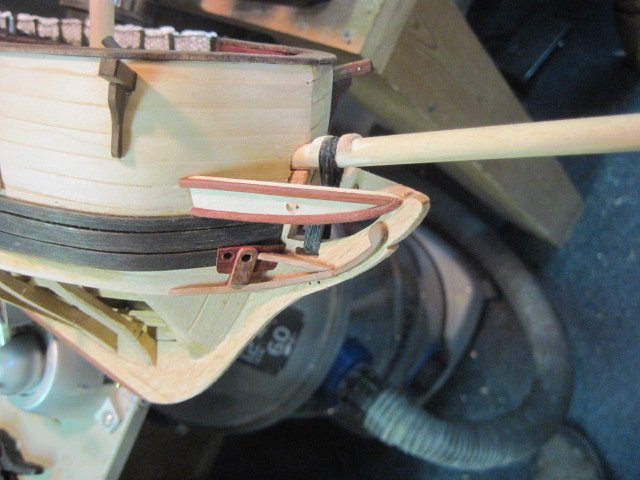
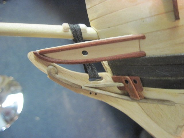
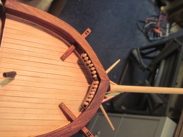
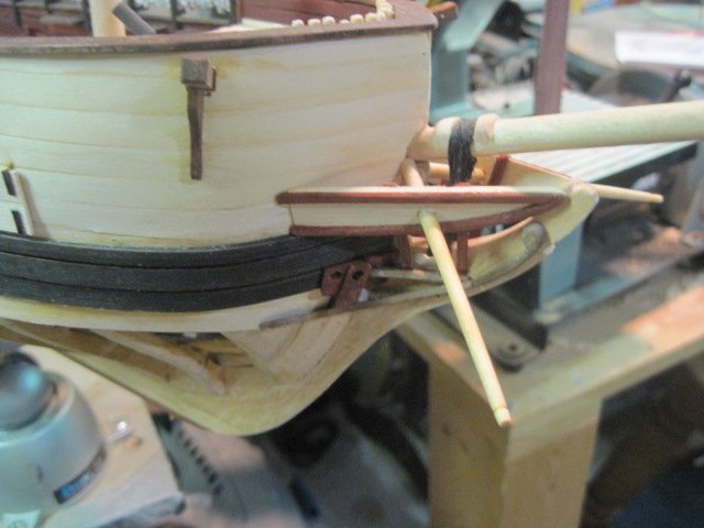
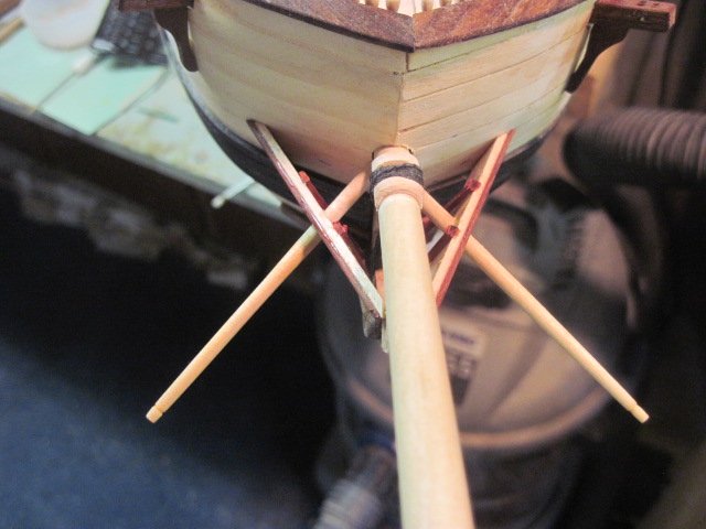
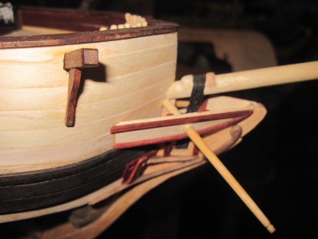
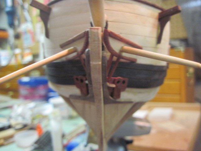
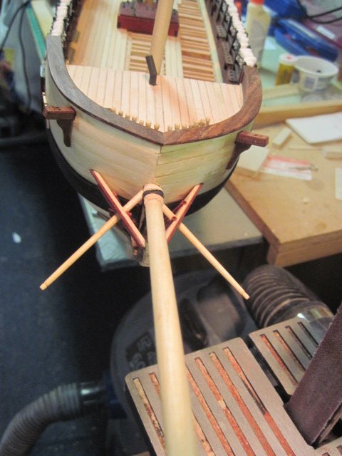
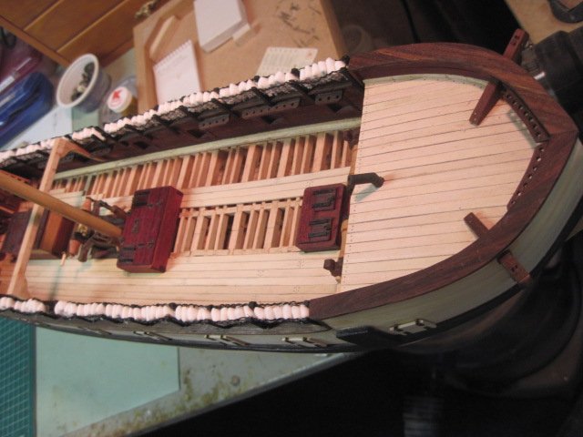
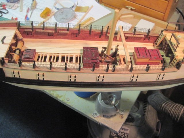
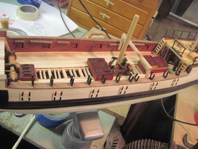
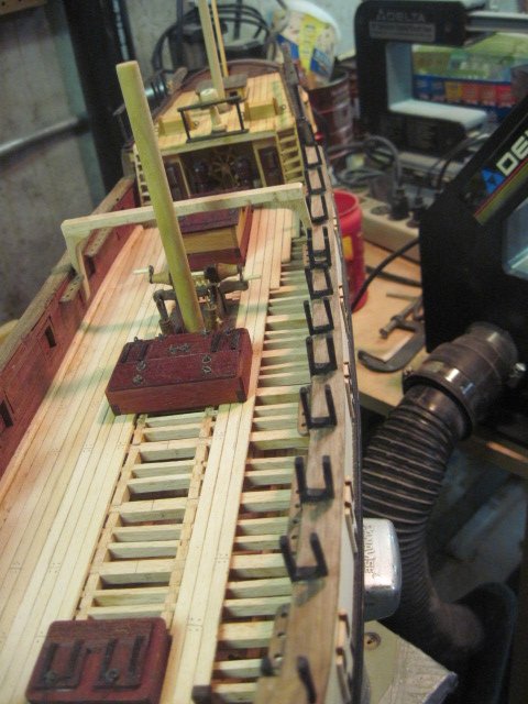
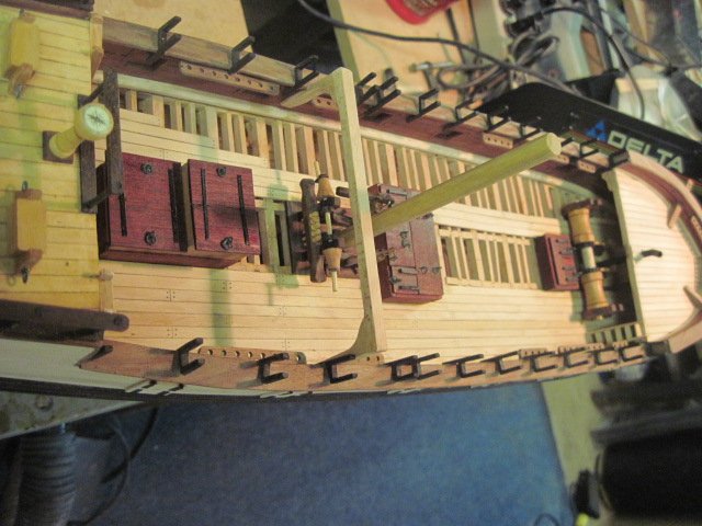
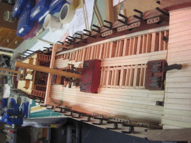
The bow was looking awful plain so I added the bowsprit and gammoning, false rail, naval hood, wash cant, lower and main rails, and bumpkins. This is a few photos of the installation.
-
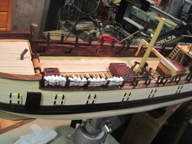
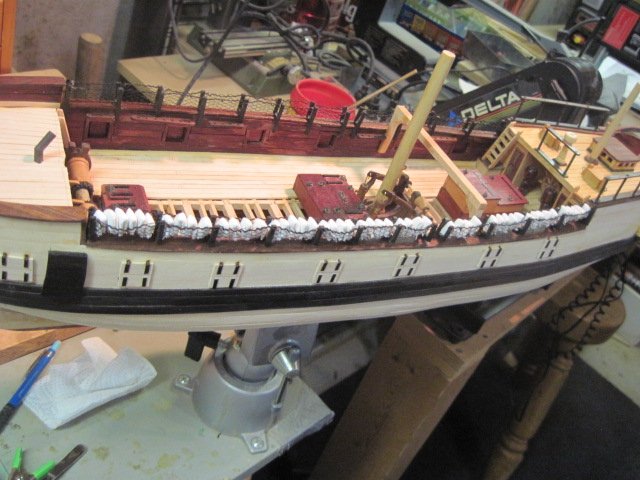
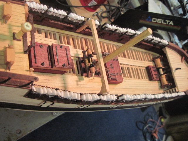
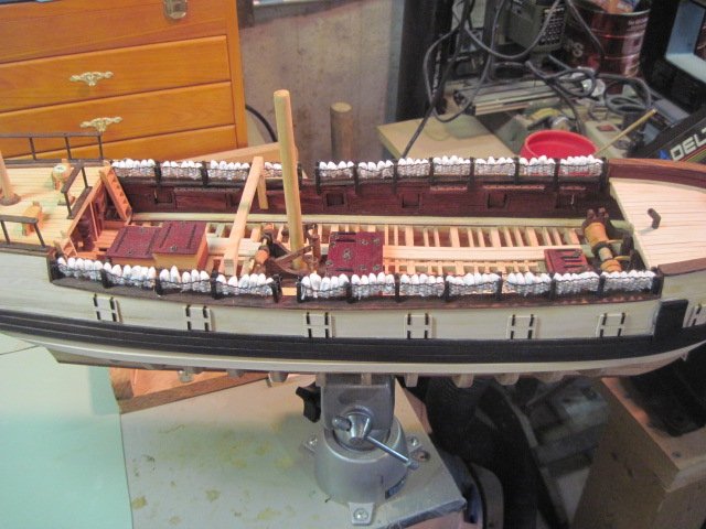
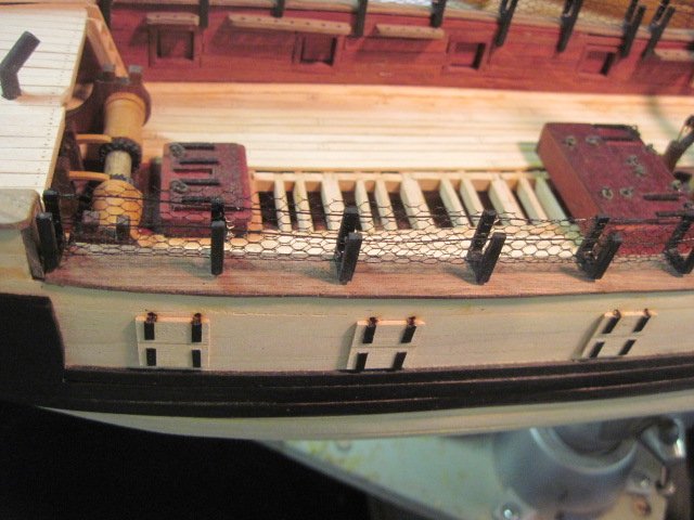
This is a few photos of the hammocks as installed on the model.
-
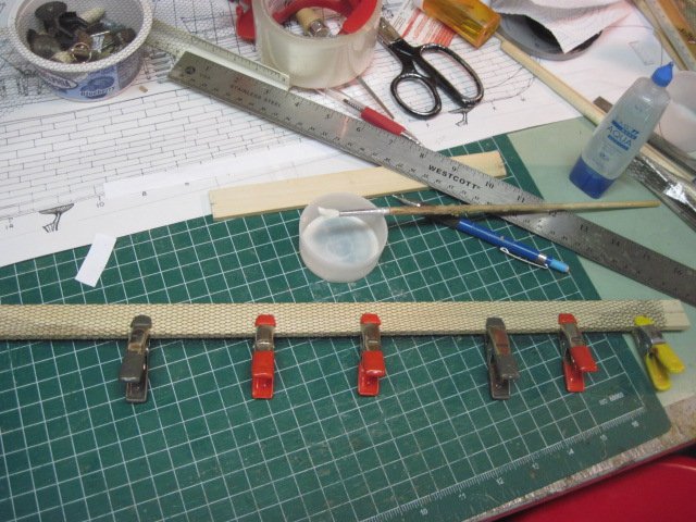
The hammock netting is made from some plastic fabric I found at Hobby Lobby it was very stiff and difficult to install inside the cranes. To solve the problem I made a mold from basswood the same thickness as the inside of the cranes and twice the height. I marked lines at the distance to the top of the cranes on both sides of the mold and secured the slightly oversized netting with clamps then applied a diluted glue solution (4:1 water to glue). After the glue dried I used a straightedge and knife to cut the netting to size. The first photo shows the netting on the mold and the glue solution the rest show the netting installed on the model. I still have to attach the netting to the support rope with some of my infamous needle work and add some hammocks.
-
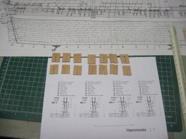
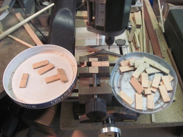
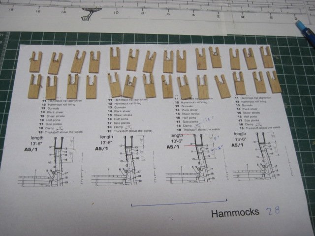
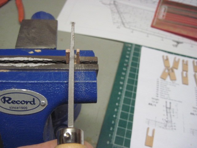
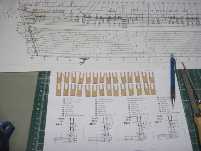
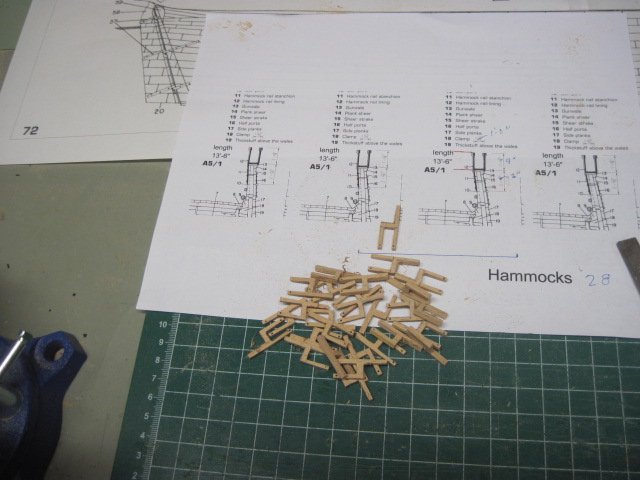
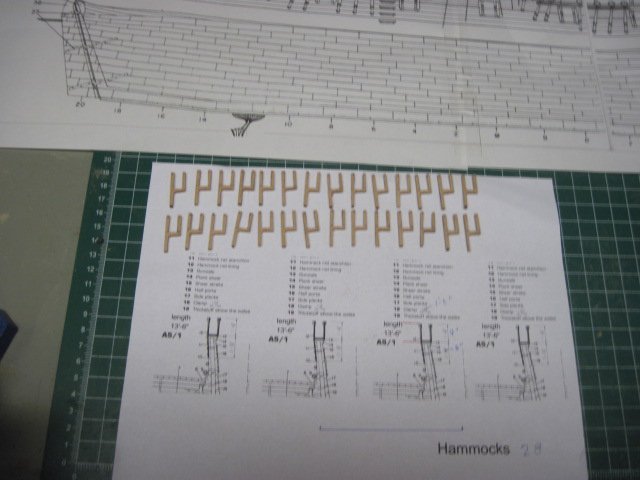
The hammock cranes looked like a good place to start after returning from the family vacation. This a few progress photos of the work so far. I cutout the blanks from Beachwood and drilled .8mm holes for the netting support rope (brass wire). I use a band saw to cut out the rough shape and finished with a square file. An ebony black stain was applied and they were installed on the model. The next step will be adding the netting and hammocks.
-
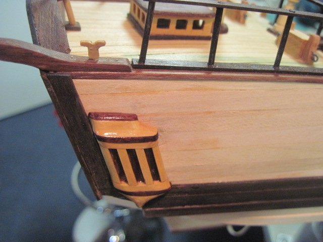
Thanks Mark, The quarter galleries did look a little better after I rounded off the corners. They were a bit too thick also. The hard part was removing them from the side of the model. Mike

-
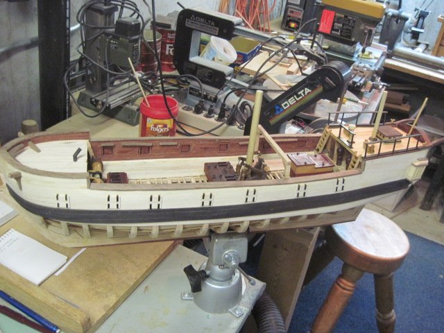
The Akbar is a fine looking work boat and you are off to a good start on her. Don’t worry about ‘catching up with the rest of us’ this is just a hobby for most of us with the exception of a few talented professionals. As you read through the different build logs you will see there are lots of ways to build a boat. Have fun and keep the pictures coming. Mike
-
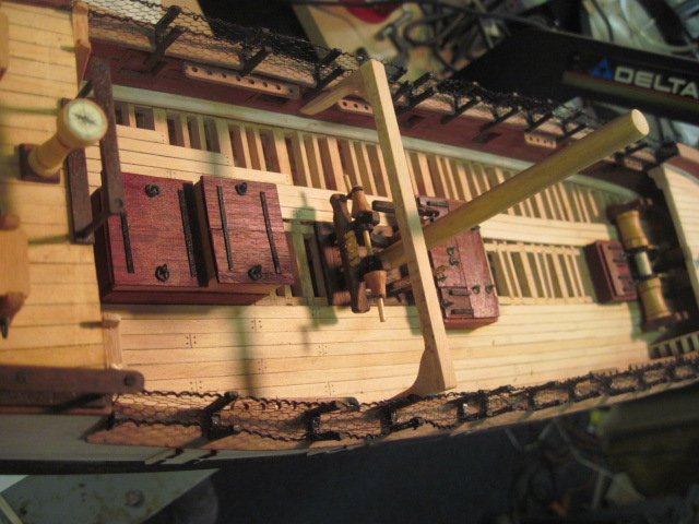
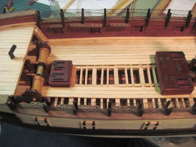
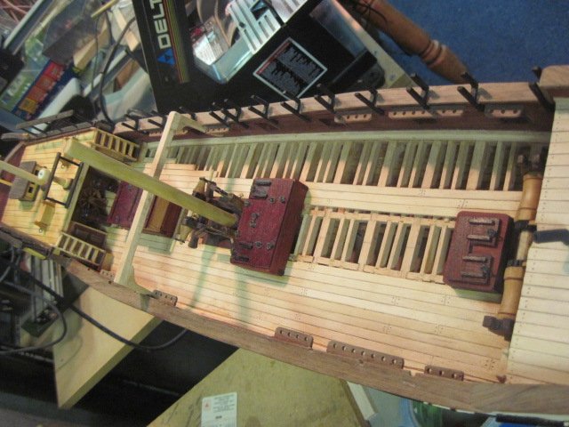
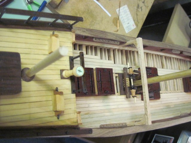
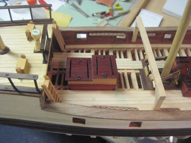
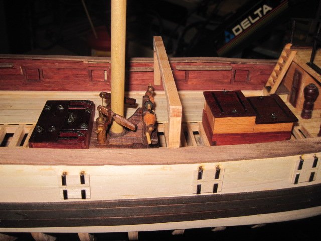
The boat beam along with the pin rails and gunport covers have been installed. All the gunport covers are shown in the closed position. There will be two cannons shown sitting on the main deck per the book drawing.

-
Battle Station by dwalker
Mike 41 replied to dwalker's topic in - Build logs for subjects built 1751 - 1800
Nice work on the cannon. Is the metal aluminum? Mike